


ViewSonic SWB5501, SWB6552, SWB8451, SWB7051, CDE8451 User Manual
...SWB5501/SWB6552/SWB7051/
SWB8451
Smart White Board
CDE5501/CDE6552/CDE7051/
CDE8451 LCD Display
User Guide
IMPORTANT: Please read this User Guide to obtain important information on installing and using your product in a safe manner, as well as registering your product for future service. Warranty information contained in this User Guide will describe your limited coverage from ViewSonic Corporation, which is also found on our web site at http:// www.viewsonic.com in English, or in specific languages using the Regional selection box in the upper right corner of our website. “Antes de operar su equipo lea cu idadosamente las instrucciones en este manual”
Model No. VS15421/VS15432/VS15633/VS15420

Compliance Information
NOTE: This section addresses all connected requirements and statements regarding regulations. Confirmed corresponding applications shall refer to nameplate labels and relevant markings on unit.
FCC Compliance Statement
This device complies with part 15 of FCC Rules. Operation is subject to the following two conditions: (1) this device may not cause harmful interference, and (2) this device must accept any interference received, including interference that may cause undesired operation.
This equipment has been tested and found to comply with the limits for a Class B digital device, pursuant to part 15 of the FCC Rules. These limits are designed to provide reasonable protection against harmful interference in a residential installation. This equipment generates, uses, and can radiate radio frequency
energy, and if not installed and used in accordance with the instructions, may cause harmful interference to radio communications. However, there is no guarantee that interference will not occur in a particular installation. If this equipment does cause harmful interference to radio or television reception, which can be determined
by turning the equipment off and on, the user is encouraged to try to correct the interference by one or more of the following measures:
•Reorient or relocate the receiving antenna.
•Increase the separation between the equipment and receiver.
•Connect the equipment into an outlet on a circuit different from that to which the receiver is connected.
•Consult the dealer or an experienced radio/TV technician for help.
Warning: You are cautioned that changes or modifications not expressly approved by the party responsible for compliance could void your authority to operate the equipment.
Industry Canada Statement
CAN ICES-3 (B)/NMB-3(B)
CE Conformity for European Countries
The device complies with the EMC Directive 2004/108/EC and Low Voltage
Directive 2006/95/EC.
Following information is only for EU-member states:
The mark shown to the right is in compliance with the Waste Electrical and
Electronic Equipment Directive 2002/96/EC (WEEE).The mark indicates the requirement NOT to dispose the equipment as unsorted municipal waste, but use the return and collection systems according to local law.
i

Declaration of RoHS2 Compliance
This product has been designed and manufactured in compliance with Directive
2011/65/EU of the European Parliament and the Council on restriction of the use of certain hazardous substances in electrical and electronic equipment (RoHS2 Directive) and is deemed to comply with the maximum concentration values issued by the European Technical Adaptation Committee (TAC) as shown below:
Substance |
Proposed Maximum |
Actual Concentration |
|
Concentration |
|||
|
|
||
Lead (Pb) |
0.1% |
< 0.1% |
|
Mercury (Hg) |
0.1% |
< 0.1% |
|
Cadmium (Cd) |
0.01% |
< 0.01% |
|
Hexavalent Chromium (Cr6+) |
0.1% |
< 0.1% |
|
Polybrominated biphenyls |
0.1% |
< 0.1% |
|
(PBB) |
|||
|
|
||
Polybrominated diphenyl ethers |
0.1% |
< 0.1% |
|
(PBDE) |
|
|
Certain components of products as stated above are exempted under the Annex III of the RoHS2 Directives as noted below:
Examples of exempted components are:
1.Mercury in cold cathode fluorescent lamps and external electrode fluorescent lamps (CCFL and EEFL) for special purposes not exceeding (per lamp):
(1)Short length ( 500 mm): maximum 3.5 mg per lamp.
(2)Medium length ( 500 mm and 1,500 mm): maximum 5 mg per lamp.
(3)Long length ( 1,500 mm): maximum 13 mg per lamp.
2.Lead in glass of cathode ray tubes.
3.Lead in glass of fluorescent tubes not exceeding 0.2% by weight.
4.Lead as an alloying element in aluminium containing up to 0.4% lead by weight.
5.Copper alloy containing up to 4% lead by weight.
6.Lead in high melting temperature type solders (i.e. lead-based alloys containing
85% by weight or more lead).
7.Electrical and electronic components containing lead in a glass or ceramic other than dielectric ceramic in capacitors, e.g. piezoelectronic devices, or in a glass or ceramic matrix compound.
ii

Cautions and Warnings
1.Read these instructions completely before using the equipment.
2.Keep these instructions in a safe place.
3.Heed all warnings and follow all instructions.
4.Always handle the LCD display with care when moving it.
5.Never remove the rear cover. This LCD display contains high-voltage parts.
You may be seriously injured if you touch them.
6.Do not use this equipment near water. Warning: To reduce the risk of fire or electric shock, do not expose this apparatus to rain or moisture.
7.Avoid exposing the LCD display to direct sunlight or another heat source. Orient the LCD display away from direct sunlight to reduce glare.
8.Clean with a soft, dry cloth. If further cleaning is required, see the “Care and Maintenance” section in this guide for further instructions.
9.Avoid touching the screen. Skin oils are difficult to remove.
10.Do not rub or apply pressure to the LCD panel, as it may permanently damage the screen.
11.Do not block any ventilation openings. Install the equipment in accordance with the manufacturer’s instructions.
12.Do not install near any heat sources such as radiators, heat registers, stoves, or other devices (including amplifiers) that produce heat.
13.Place the LCD display in a well ventilated area. Do not place anything on the LCD display that prevents heat dissipation.
14.Do not place heavy objects on the LCD display, video cable, or power cord.
15.If smoke, an abnormal noise, or a strange odor is present, immediately switch the LCD display off and call your dealer or ViewSonic. It is dangerous to continue using the LCD display.
16.Do not attempt to circumvent the safety provisions of the polarized or groundingtype plug. A polarized plug has two blades with one wider than the other. A grounding type plug has two blades and a third grounding prong. The wide blade and the third prong are provided for your safety. If the plug does not fit into your outlet, consult an electrician for replacement of the outlet.
17.Protect the power cord from being tread upon or pinched, particularly at the plug, and the point where if emerges from the equipment. Be sure that the power outlet is located near the equipment so that it is easily accessible.
18.Only use attachments/accessories specified by the manufacturer.
(Continued on next page)
iii

19.Use only with the cart, stand, tripod, bracket, or table specified by the manufacturer, or sold with the equipment. When a cart is used, use caution when moving the cart/equipment combination to avoid injury from tipping over.
20.Unplug this equipment when it will be unused for long periods of time.
21.Refer all servicing to qualified service personnel. Service is required when the unit has been damaged in any way, such as: if the power-supply cord or plug is damaged, if liquid is spilled onto or objects fall into the unit, if the unit is exposed to rain or moisture, or if the unit does not operate normally or has been dropped.
iv

Contents |
|
|
Compliance Information |
|
|
FCC Compliance Statement................................................................ |
i |
|
Industry Canada Statement................................................................. |
i |
|
CE Conformity for European Countries............................................... |
i |
|
Declaration of RoHS2 Compliance...................................................... |
ii |
|
Cautions and Warnings....................................................................... |
iii |
|
Copyright Information |
|
|
Product Registration........................................................................... |
2 |
|
For Your Records................................................................................ |
2 |
|
1. Getting Started |
|
|
1.1 |
Package Contents......................................................................... |
3 |
1.2 |
Wall Mount Kit Specifications (VESA)........................................... |
4 |
2. Smart Whiteboard/LCD Display |
|
|
Features |
|
|
2.1 |
Control Panel Overview................................................................ |
5 |
2.2 |
Terminal Interface Overview......................................................... |
8 |
2.3 |
Remote Control Overview........................................................... |
11 |
2.4 |
Inserting Remote Control Batteries............................................. |
13 |
2.5 |
Remote Control Receiver Range................................................ |
14 |
3. Setting Up Your Display |
|
|
3.1 |
Connecting an External PC......................................................... |
15 |
3.2 |
RS232 Connections.................................................................... |
18 |
3.3 |
Connecting USB Peripherals...................................................... |
19 |
3.4 |
AV IN Connections...................................................................... |
22 |
3.5 |
S-Video Connections.................................................................. |
24 |
3.6 |
YPbPr Connections..................................................................... |
25 |
3.7 |
HDMI Connections...................................................................... |
26 |
3.8 |
Microphone Connections............................................................ |
27 |
3.9 |
Coaxial Connections................................................................... |
28 |
3.10 VGA Connections..................................................................... |
29 |
|
3.11 AV OUT Connections................................................................ |
31 |
|
v

4.Basic Display Operations
5.OSD Menu Operation
5.1 |
Input Source................................................................................ |
33 |
5.2 |
Screen Menu............................................................................... |
37 |
5.3 |
Picture Menu............................................................................... |
39 |
5.4 Sound Menu (SWB5501/SWB6552/SWB7051/CDE5501/ |
|
|
|
CDE6552/CDE7051 Models)...................................................... |
41 |
5.5 Time Menu (SWB5501/SWB6552/SWB7051/CDE5501/ |
|
|
|
CDE6552/CDE7051 Models)...................................................... |
42 |
5.6 Lock Menu (SWB5501/SWB6552/SWB7051/CDE5501/ |
|
|
|
CDE6552/CDE7051 Models)...................................................... |
43 |
5.7 Setup Menu (SWB5501/SWB6552/SWB7051/CDE5501/ |
|
|
|
CDE6552/CDE7051 Models)...................................................... |
44 |
5.8 |
Annotation Menu (SWB8451/CDE8451 Models)........................ |
45 |
5.9 |
Android System Interface (SWB8451/CDE8451 Models)........... |
46 |
5.10 Multimedia File Playback Interface (SWB8451/CDE8451 |
|
|
|
Models)..................................................................................... |
51 |
6.Trouble Shooting
7.Care and Maintenance
8.Display Modes
8.1 YPbPr Mode................................................................................ |
57 |
8.2 VGA Mode.................................................................................. |
57 |
8.3 HDMI Mode................................................................................. |
58 |
9.Specifications
10.RS-232 Protocol
10.1 |
Introduction............................................................................... |
60 |
10.2 |
Description................................................................................ |
60 |
10.2.1 Hardware specification........................................................... |
60 |
|
10.2.2 Communication Setting.......................................................... |
61 |
|
10.2.3 Command Message Reference............................................. |
61 |
|
10.3 |
Protocol..................................................................................... |
61 |
10.3.1 Set-Function Listing............................................................... |
61 |
|
vi

10.3.2 Get-Function Listing............................................................... |
67 |
10.3.3 Remote Control Pass-through mode..................................... |
70 |
Other Information |
|
Customer Support............................................................................. |
72 |
Limited Warranty............................................................................... |
73 |
Mexico Limited Warranty.................................................................. |
75 |
vii
Copyright Information
Copyright © ViewSonic Corporation, 2014. All rights reserved.
Macintosh and Power Macintosh are registered trademarks of Apple Inc.
Microsoft, Windows, and the Windows logo are registered trademarks of Microsoft
Corporation in the United States and other countries.
ViewSonic, the three birds logo, OnView, ViewMatch, and ViewMeter are registered trademarks of ViewSonic Corporation.
VESA is a registered trademark of the Video Electronics Standards Association. DPMS, DisplayPort, and DDC are trademarks of VESA.


 is a trademark of SRS Labs, Inc.
Premium Sound technology is incorporated under license from SRS Labs, Inc.
ENERGY STAR® is a registered trademark of the U.S. Environmental Protection
Agency (EPA).
As an ENERGY STAR® partner, ViewSonic Corporation has determined that this product meets the ENERGY STAR® guidelines for energy efficiency.
Disclaimer: ViewSonic Corporation shall not be liable for technical or editorial errors or omissions contained herein; nor for incidental or consequential damages resulting from furnishing this material, or the performance or use of this product.
In the interest of continuing product improvement, ViewSonic Corporation reserves the right to change product specifications without notice. Information in this document may change without notice.
No part of this document may be copied, reproduced, or transmitted by any means, for any purpose without prior written permission from ViewSonic Corporation.
1

Product Registration
To fulfill possible future product needs, and to receive additional product information as it becomes available, please visit your region section on ViewSonic’s website to register your product online.
The ViewSonic CD also provides an opportunity for you to print the product registration form. Upon completion, please mail or fax to a respective ViewSonic office. To find your registration form, use the directory “:\CD\Registration”.
Registering your product will best prepare you for future customer service needs.
Please print this user guide and fill the information in the “For Your Records” section. Your LCD displays serial number is located on the rear side of the display.
For additional information, please see the “Customer Support” section in this guide.
For Your Records
Product Name: SWB5501/SWB6552/SWB7051/SWB8451
ViewSonic Smart White Board CDE5501/CDE6552/CDE7051/CDE8451 ViewSonic LCD Display
Model Number: VS15421/VS15432/VS15633/VS15420
Document Number: SWB5501/SWB6552/SWB7051/SWB8451/CDE5501/ CDE6552/CDE7051/CDE8451_UG_ENG
Rev. 1D 03-31-14
Serial Number: _______________________________________
Purchase Date: _______________________________________
Product disposal at end of product life
ViewSonic respects the environment and is committed to working and living green. Thank you for being part of Smarter, Greener Computing.
Please visit ViewSonic website to learn more.
USA & Canada: http://www.viewsonic.com/company/green/recycle-program/ Europe: http://www.viewsoniceurope.com/uk/support/recycling-information/
Taiwan: http://recycle.epa.gov.tw/recycle/index2.aspx
2
1. Getting Started
Congratulations on your purchase of a ViewSonic® Smart Whiteboard/LCD display.
Important! Save the original box and all packing material for future shipping needs.
Note: The word “Windows” in this user guide refers to Microsoft Windows operating system.
1.1 Package Contents
•Power cable
•VGA cable
•Remote control
•AAA battery x 2
•USB cable
•Audio cable
•Stylus pen x 3
•AV cable (for SWB6552/SWB7051/SWB8451/CDE6552/CDE7051/CDE8451 models only)
•YPbPr cable (for SWB6552/SWB7051/CDE6552/CDE7051 models only)
•Wall mount installation guide
•User manual CD wizard
-User Guide
-ViewBoard software
3
1.2 Wall Mount Kit Specifications (VESA)
Please follow the instructions in the wall mount installation guide to install your wall mount or mobile mount bracket. If attaching to other building materials, please contact your nearest dealer.
inch |
VESA Spec. (A x B) |
Standard Screw (C x D) |
Quantity |
55 |
400 x 400 mm |
M8 x L40 |
4 |
65 |
600 x 400 mm |
M8 x L40 |
4 |
70 |
600 x 600 mm |
M8 x L40 |
4 |
84 |
600 x 600 mm |
M8 x L40 |
8 |
•ViewSonic provides the standard dimensions for wall mount kits as shown in the table above.
•To find the perfect mount, please browse www.viewsonic.com or call our service team: United States 1-800-688-6688, Canada 1-866-463-4775.
•When purchasing our wall mount kit, a detailed install manual and all parts necessary for assembly are provided.
•Do not use the screws that longer than the standard dimension, as they may cause damage to the inside of the LCD display set.
4
2. Smart Whiteboard/LCD Display
Features
This section introduces you to the features of your Smart Whiteboard/LCD Display.
Note: The features or applications described in this User’s manual may vary depending on the device model purchased.
2.1 Control Panel Overview
SWB5501/CDE5501 Control Panel:
|
6 |
|
7 |
Item |
Description |
|
Power On/Off |
INPUT |
Switch between different sources |
MENU |
OSD Menu On/Off |
CH. |
Move upward/downward to scroll through menu options. |
VOL+/- |
Increase or decrease volume |
RC Receiver |
Receives signals from the remote control |
Power Indicator |
Indicates power status (On/Off) |
5
SWB6552/SWB7051/CDE6552/CDE7051 Control Panel:
ENERGY |
ZOOM VOL- VOL+ PC/VGA |
INPUT |
|
SAVING |
|||
|
|
PC USB |
PC USB |
Item |
Description |
|
Power On / Off switch |
|
|
INPUT |
Switch to different source |
|
|
PC/VGA |
Switch between PC and VGA sources |
|
|
VOL+/- |
Increase or decrease volume |
|
|
ZOOM |
Adjust screen ratio |
|
|
ENERGY SAVING |
Energy-saving mode |
|
|
PC USB |
Internal PC USB port |
|
|
RC Receiver |
Receives signals from the remote control |
|
|
Power Indicator |
Indicates power status (On / Off) |
|
|
6
SWB8451/CDE8451 Control Panel:
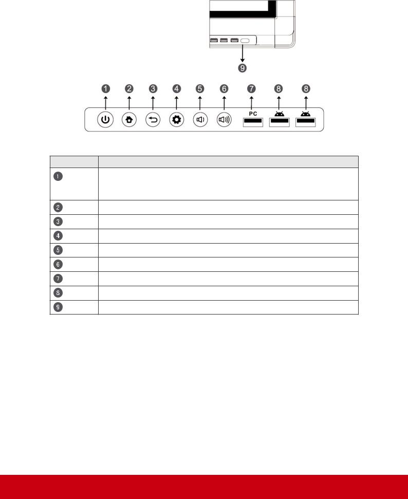
Item Description
Press the key to turn on the device
Press the key to turn on/off the screen Press and hold the key to turn off the device
Back to Android main interface
Return to Android previous level
Call up function menu
Decrease volume
Increase volume
Internal PC USB port
Display USB port for Android system
Receives signals from the remote control
7
2.2 Terminal Interface Overview
SWB5501/CDE5501 Interface:
|
|
|
|
|
|
|
|
|
|
|
|
|
|
|
|
|
|
|
|
|
|
|
|
|
|
|
|
|
|
|
|
|
|
|
|
|
|
|
|
|
|
|
|
|
|
|
|
|
|
|
|
|
|
|
|
|
|
|
|
|
|
|
|
|
|
|
|
|
|
|
|
|
|
|
|
|
|
|
|
|
|
|
|
|
|
|
|
|
|
|
|
|
|
|
|
|
|
|
|
|
|
|
|
|
|
|
|
|
|
|
|
|
|
|
|
|
|
|
|
|
|
|
|
|
|
|
|
|
|
|
|
|
|
|
|
|
|
|
|
|
|
|
|
|
|
|
|
|
|
|
|
|
|
|
|
|
|
|
|
|
|
|
|
|
|
|
|
|
|
|
|
|
|
|
|
|
|
|
|
|
|
|
|
|
|
|
|
|
|
|
|
|
|
|
|
|
|
|
|
|
|
|
|
|
|
|
|
|
|
|
|
|
|
|
|
|
|
|
|
|
|
|
|
|
|
|
|
|
|
|
|
|
|
|
|
|
|
|
|
|
|
|
|
|
|
|
|
|
|
|
|
|
|
|
|
|
|
|
|
|
|
|
|
|
|
|
|
|
|
|
|
|
|
|
|
|
|
|
|
|
|
|
|
|
|
|
|
|
|
|
|
|
|
|
|
|
Item |
Description |
|||||||||||||||||||||||||
AUDIO OUT |
Connects the device to headphones or speakers |
|||||||||||||||||||||||||
MIC |
Connects to a microphone |
|||||||||||||||||||||||||
USB IN |
Connects USB peripherals such as HDDs USB keyboards, |
|||||||||||||||||||||||||
mice and more |
||||||||||||||||||||||||||
|
||||||||||||||||||||||||||
VGA OUT |
Connects the display with the VGA-IN connector |
|||||||||||||||||||||||||
LAN IN |
Standard RJ45 (10M/100M/1G) Internet connection interface |
|||||||||||||||||||||||||
USB IN |
Display Motherboard Upgrade Interface |
|||||||||||||||||||||||||
HDMI |
High Definition Multimedia Interface |
|||||||||||||||||||||||||
S-VIDEO |
S-VIDEO input |
|||||||||||||||||||||||||
COAXIAL |
Coaxial output |
|||||||||||||||||||||||||
AUDIO IN |
Connects the device to external audio sources |
|||||||||||||||||||||||||
VGA IN |
Connects the device to external video sources |
|||||||||||||||||||||||||
AV OUT |
Audio-Video output port |
|||||||||||||||||||||||||
TOUCH OUT |
External PC touch-signal input |
|||||||||||||||||||||||||
AV IN |
Audio-Video combined input port |
|||||||||||||||||||||||||
COMPONENT |
YPbPr signal input, connect DVD, set -top -box with YPbPr |
|||||||||||||||||||||||||
RS232 |
Serial port interface |
|||||||||||||||||||||||||
AC IN |
AC power input |
|||||||||||||||||||||||||
POWER |
Power On / Off switch |
|||||||||||||||||||||||||
Note: Model nos. CDE5501 do not have interface features #1 – 5 if the optional slot-in PC module is not installed.
8
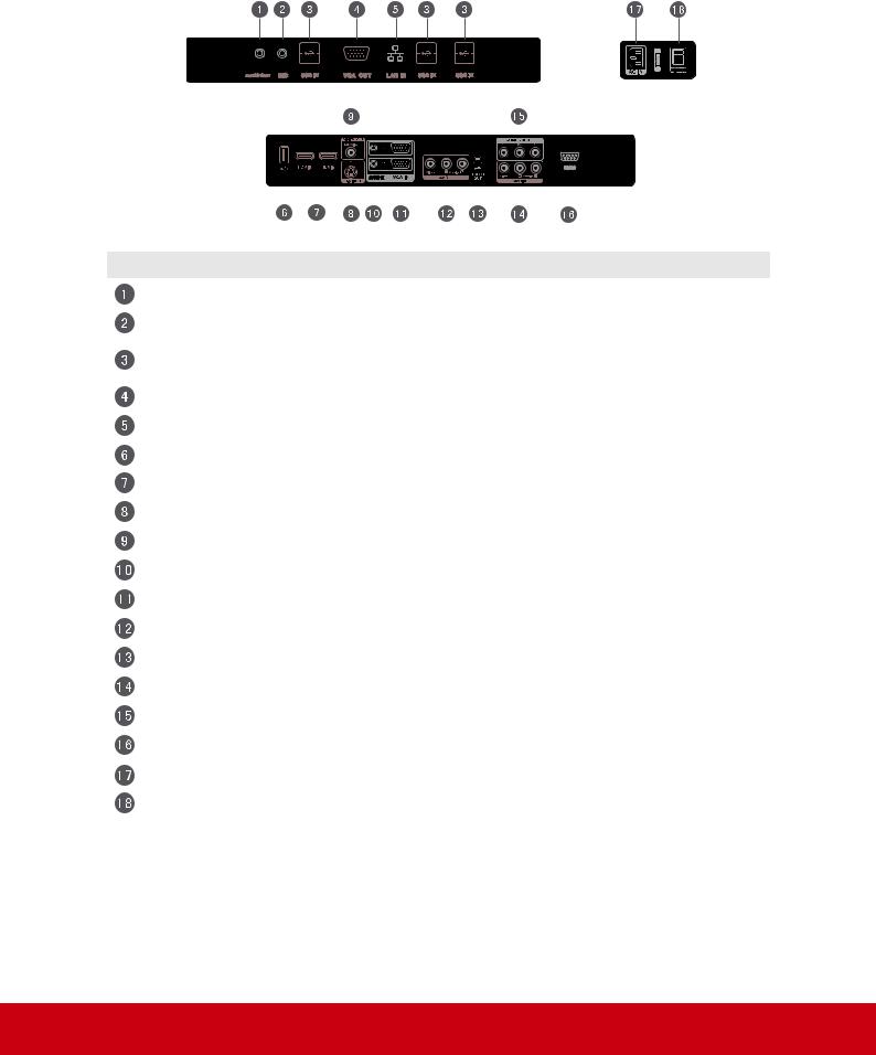
SWB6552/SWB7051/CDE6552/CDE7051 Interface:
Item |
Description |
LAN IN |
Standard RJ45 (10M/100M/1G) Internet connection interface |
VGA OUT |
Connects the display to a VGA-IN connector |
MIC |
Connects to a microphone |
AUDIO OUT |
Connects the device to headphones or speakers |
USB IN |
Connects USB peripherals such as HDDs USB keyboards and |
|
mice |
|
Display Motherboard Upgrade Interface |
TOUCH |
Touch signal input, controls an external PC once the driver has |
|
been installed (available through PC, VGA and HDMI sources). |
HDMI IN |
High Definition Multimedia Interface |
COAXIAL |
Coaxial output |
VGA IN |
Connects the device to external video sources |
AUDIO IN |
Connects the device to external audio sources |
YPbPr IN |
YPbPr signal input, connects to DVD players and set-top boxes |
AV IN |
Audio-Video combined input port |
AV OUT |
Audio-Video output port |
MIC IN |
Connects to a microphone |
RS232 |
Serial port interface |
AC IN |
AC power input |
POWER |
Power On / Off switch |
Note: Model no. CDE6552/CDE7051 does not have interface features
#1 – 5 if the optional slot-in PC module is not installed.
9

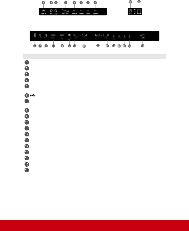
SWB8451/CDE8451 Interface:
Item Description
USB interface, connect USB devices such as mobile hard disk, U disk, USB keyboard and mouse, USB drives, etc
High Definition Multimedia Interface, HDMI3 can realize MHL function, HDMI4 can realize 4Kx2K
Connected to display devices with VGA input function
Connects the device to external audio sources
Connects the device to external video sources
Touch signal input, controls an external PC once the driver has been installed (available through PC, VGA and HDMI sources).
Audio-Video combined input port
Coaxial output
Serial port interface
Connects the device to headphones or speakers
Standard RJ45 (10M/100M/1G) Internet connection interface (This network port is only used for Android system)
AC power input
Power On / Off switch
Standard RJ45 (10M/100M/1G) Internet connection interface (This network port is only used for PC)
Connects the device to headphones or speakers
Connects to a microphone
Connects the display to a VGA-IN connector
Connects the display to a DisplayPort connector
Connected to device with HDMI input function
USB 3.0 interface , connects USB peripherals such as HDDs USB keyboards and mice
USB 2.0 interface , connects USB peripherals such as HDDs USB keyboards and mice
Note: Model no. CDE8451 does not have interface features #14 – 21 if the optional slot-in PC module is not installed.
10
2.3 Remote Control Overview
11
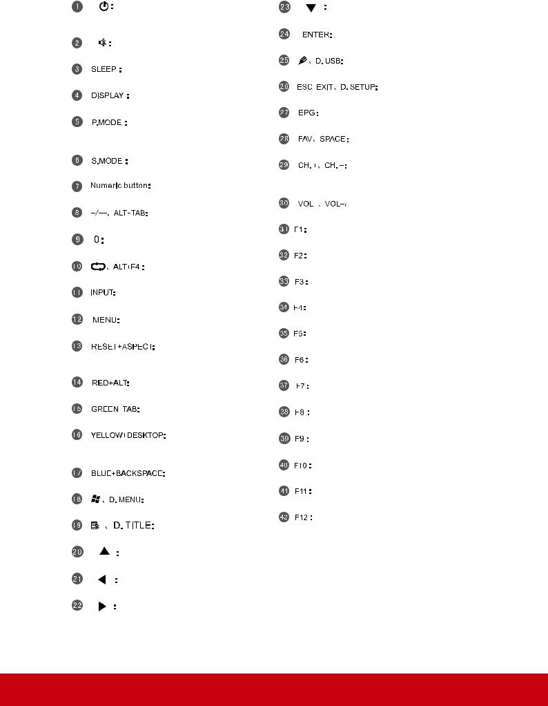
Press to turn the display ON/OFF (Standby), or press and hold for 5 seconds to shut down
Mute / Unmute
Set the sleep time function (55", 65", 70") Display information of the current input source
Picture mode selection (55", 65", 70")
Blank screen (84")
Sound mode selection (55", 65", 70")
Numeric input button
Press to switch between PC applications Numeric input button
Close current PC window
Source selection button
Press to display Menu
Adjust the aspect ratio of PC, HDMI and VGA sources (55", 65", 70")
PC ‘Alt’ button (55", 65", 70")
PC ‘Tab’ button (55", 65", 70")
Switch to Windows Desktop
Switch to Android main screen (84")
PC ‘Backspace’ button
PC ‘Windows’ button
PC ‘Menu’ button (55", 65", 70")
Press to scroll up
Press to scroll left
Press to scroll right
Press to scroll down
Enter button. Press it to select options. Writing software startup
Shortcut button to exit dialog boxes Digital program guide (not available) PC ‘Space’ button
CH+ : PC previous page (84") CH- : PC next page (84")
Increase / Decrease volume
F1 Function
F2 Function
F3 Function
4 Function
F5 Function
F6 Function
F7 Function
F8 Function
F9 Function
F10 Function
F11 Function
F12 Function
12
2.4 Inserting Remote Control Batteries
To insert the provided batteries into the remote control follow these instructions. We recommend that you don’t mix battery types.
1.Remove the cover on the rear of the remote control.
2.Insert two “AAA” batteries, ensuring the “+” symbol on the battery matches the
“+” on the battery post.
3.Replace the cover by aligning it with the slot on the remote control and snapping the latch shut.
Warning: There is a risk of explosion if batteries are replaced with the incorrect type.
Note: Always dispose of old batteries in an environmentally friendly way. Contact your local government for more information on how to dispose of batteries safely.
13
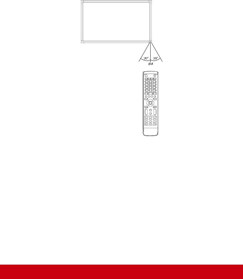
2.5 Remote Control Receiver Range
The working range of the remote control receiver is shown here. It has an effective range of 8 meters. Make sure there is nothing obstructing the remote control’s signal to the receiver.
14
3. Setting Up Your Display
Warning: For the safety of you and your unit, please do not connect to a power supply before the external device is prepared.
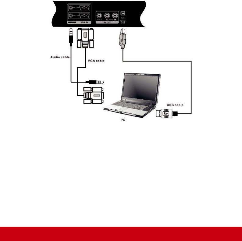
3.1 Connecting an External PC
SWB5501/CDE5501 Models:
15
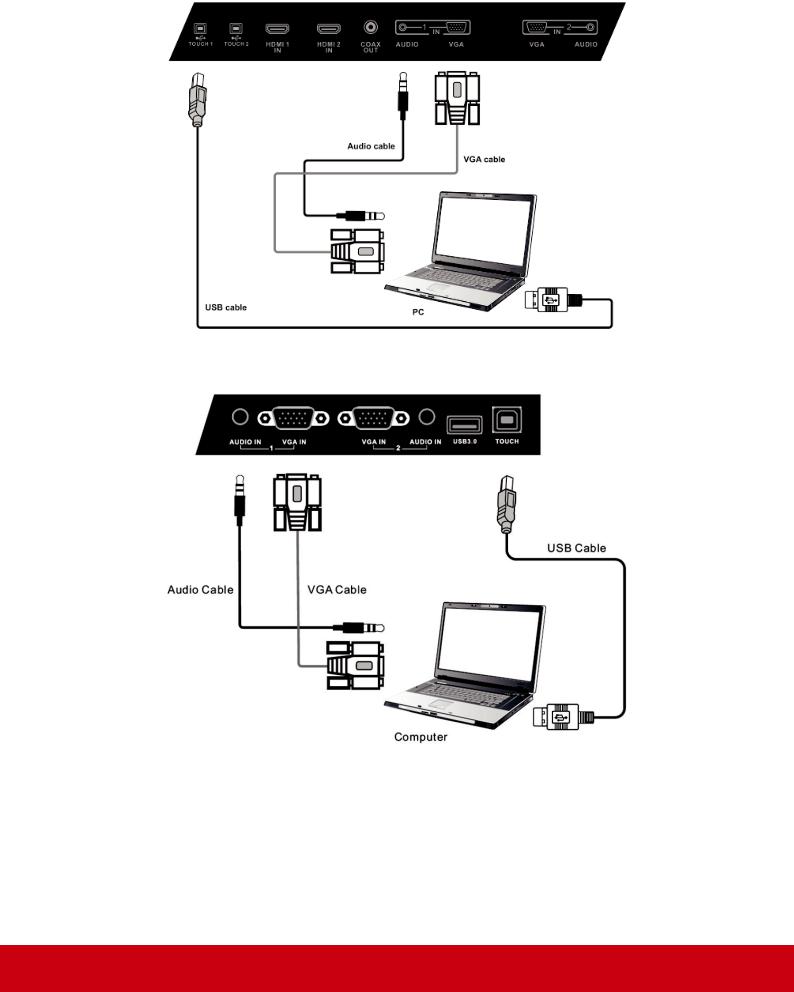
SWB6552/SWB7051/CDE6552/CDE7051 Models:
SWB8451/CDE8451 Models:
1.To display video and sound from an external PC follow the instructions below.
Note: External PCs can also be connected to the display via HDMI cable.
•Connect a VGA cable (15-pin) from your external PC to the VGA IN port on the display.
•Connect an audio cable from the AUDIO OUT port on your external PC to the
AUDIO IN port on the display.
16
2.Connect a USB cable to the external PC from the TOUCH OUT port of the display.
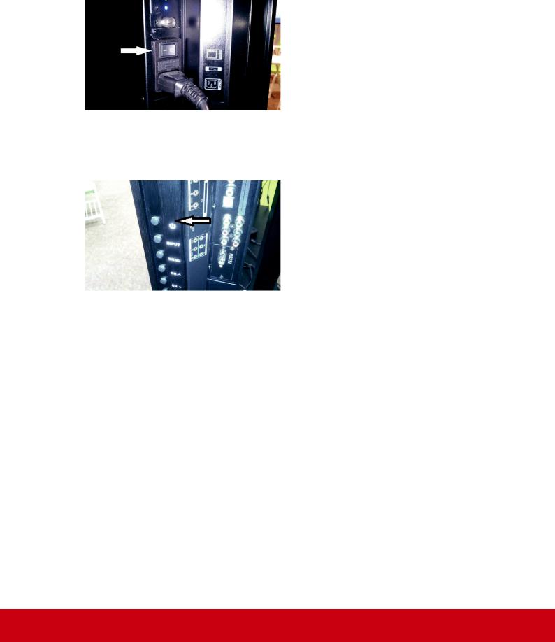
3.Plug the power cord into the rear panel of the display and flip the power switch
(I/O) to the “I” position. The display is now in “Standby” mode.
4.Turn on your external computer and set up the touch driver.
5.Press the  button on the right-hand side of the display to turn on the screen.
6. Press the INPUT button to switch to the “PC” source.
Note: For optimal results, select 1920x1080p as the external computer's input resolution.
17
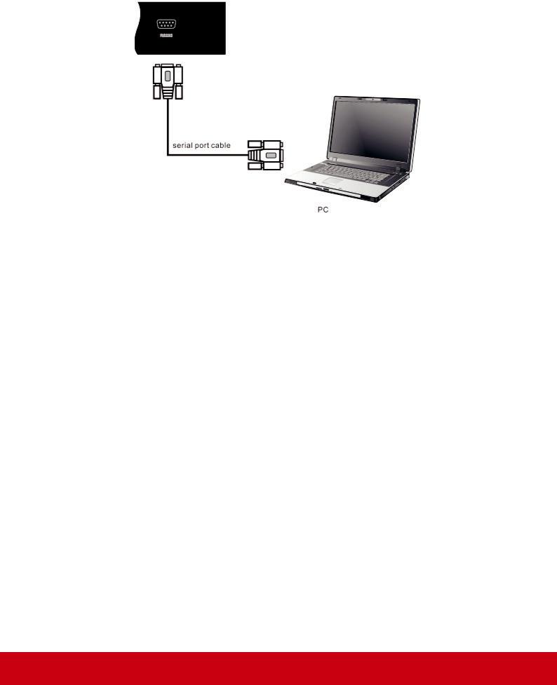
3.2 RS232 Connections
When you use a RS232 serial port cable to connect your display to an external computer, certain functions can be controlled by the PC, including power on/off, volume adjustment and more.
18
 Loading...