


VM-3500E
25 Watt VHF/FM
Marine Transceiver
Owner's Manual
Oversized alphanumeric LCD, knobs and keys
30 W Loud Hailer with listen back and 4 fog horns, Bells & Whistles
Direct keypad entry of a channel using the keypad
Removable ClearVoice speaker microphone with 16/9 key and channel selection
Display shows channel names, and repeats GPS information
Capable of connecting an optional enhanced RAM+ second station remote microphone
DSC distress call automatically broadcasts lat/long and vessel ID
DSC position request function and NMEA data input/output to connect to GPS Plotter
Versatile user-programmable Scanning, Priority Scan and Dual Watch
One-button access to Channel 16 and 9
with GPS attached
VM-3500E |
Page 1 |
|
|

TABLE OF CONTENTS
1 |
GENERAL INFORMATION ..................................................................................... |
4 |
|
2 |
PACKING LIST ........................................................................................................ |
4 |
|
3 |
OPTIONS ................................................................................................................. |
4 |
|
4 |
INSTALLATION NOTE ............................................................................................ |
5 |
|
5 |
GETTING STARTED ............................................................................................... |
6 |
|
|
5.1 |
ABOUT VHF RADIO ...................................................................................... |
6 |
|
5.2 |
SELECTING AN ANTENNA .......................................................................... |
6 |
|
5.3 |
COAXIAL CABLE ........................................................................................... |
7 |
6 |
INSTALLATION ....................................................................................................... |
8 |
|
|
6.1 |
LOCATION ....................................................................................................... |
8 |
|
6.2 |
ELECTRICAL CONNECTIONS...................................................................... |
8 |
|
6.3 |
ACCESSORY CABLE .................................................................................... |
9 |
|
6.4 |
CONNECTION OF GPS WITH NMEA OUTPUT ..................................... |
10 |
|
6.5 |
CHECKING GPS CONNECTIONS ............................................................. |
10 |
|
6.6 |
CHANGING THE GPS TIME ...................................................................... |
11 |
|
6.7 |
CHANGING THE TIME LOCATION ........................................................... |
12 |
|
6.8 |
CHANGING COG TO TRUE OR MAGNETIC ......................................... |
13 |
|
6.9 |
OPTIONAL MMB-84 FLUSH MOUNT INSTALLATION ............................ |
14 |
|
6.10 OPTIONAL ENHANCED RAM+ SECOND STATION MIC INSTALLATION ..... |
15 |
|
7 |
CONTROLS AND INDICATORS .......................................................................... |
16 |
|
8 |
BASIC OPERATION ............................................................................................. |
22 |
|
|
8.1 |
RECEPTION .................................................................................................. |
22 |
|
8.2 |
TRANSMISSION ........................................................................................... |
22 |
|
8.3 |
TRANSMIT TIME-OUT TIMER (TOT) ......................................................... |
23 |
|
8.4 |
SIMPLEX/DUPLEX CHANNEL USE ........................................................... |
23 |
|
8.5 |
USA, CANADA, AND INTERNATIONAL MODE ......................................... |
23 |
|
8.6 |
NOAA WEATHER CHANNELS ................................................................... |
23 |
|
8.7 |
NOAA WEATHER ALERT ........................................................................... |
24 |
|
8.8 |
NOAA WEATHER ALERT TESTING ......................................................... |
24 |
|
8.9 |
CALLING ANOTHER VESSEL (CHANNEL 16 OR 9).............................. |
25 |
|
8.10 |
DUAL WATCH (TO CH16) ......................................................................... |
25 |
|
8.11 |
SCANNING.................................................................................................. |
26 |
|
8.11.1 SELECTING THE SCAN MODE .......................................................... |
26 |
|
|
8.11.2 MEMORY SCANNING (M-SCAN) ...................................................... |
26 |
|
|
8.11.3 PRIORITY SCANNING (P-SCAN) ...................................................... |
26 |
|
|
8.12 |
PA/FOG OPERATION ................................................................................ |
28 |
|
8.12.1 Operating the PA HAIL mode ............................................................... |
28 |
|
|
8.12.2 Operating the FOG HORN mode......................................................... |
28 |
|
|
8.13 |
NAVIGATION INDICATION ........................................................................ |
29 |
|
8.14 |
LCD DIMMER .............................................................................................. |
29 |
|
8.15 |
INTERCOM OPERATION .......................................................................... |
30 |
|
8.15.1 COMMUNICATION............................................................................... |
30 |
|
|
8.15.2 CALLING .............................................................................................. |
30 |
|
|
8.16 |
VOICE SCRAMBLER................................................................................. |
31 |
Page 2 |
VM-3500E |

TABLE OF CONTENTS
9 |
DIGITAL SELECTIVE CALLING .......................................................................... |
32 |
|
|
9.1 |
GENERAL ...................................................................................................... |
32 |
|
9.2 MARITIME MOBILE SERVICE IDENTITY (MMSI) ....................................... |
33 |
|
|
|
9.2.1 What is an MMSI? .................................................................................. |
33 |
|
|
9.2.2 Programming the MMSI ....................................................................... |
33 |
|
9.3 |
DSC DISTRESS CALL ................................................................................ |
34 |
|
|
9.3.2 Receiving a DSC Distress Call .......................................................... |
35 |
|
9.4 |
ALL SHIPS CALL ........................................................................................ |
36 |
|
|
9.4.1 Transmitting an All Ships Call ............................................................ |
36 |
|
|
9.4.2 Receiving an All Ships Call ................................................................ |
37 |
|
9.5 |
INDIVIDUAL CALL ....................................................................................... |
37 |
|
|
9.5.1 Setting up the Individual Directory ..................................................... |
37 |
|
|
9.5.2 Setting up Individual Call Ringer........................................................ |
38 |
|
|
9.5.3 Transmitting an Individual Call ............................................................ |
39 |
|
|
9.5.4 Receiving an Individual Call ................................................................ |
41 |
|
9.6 |
GROUP CALL............................................................................................... |
41 |
|
|
9.6.1 Setup a Group Call .............................................................................. |
41 |
|
|
9.6.2 Transmitting a Group Call ................................................................... |
43 |
|
|
9.6.3 Receiving a Group Call ....................................................................... |
44 |
|
9.7 |
MANUAL SETTING OF THE GPS LOCATION........................................ |
45 |
10 |
RADIO SETUP MODE .......................................................................................... |
46 |
|
|
10.1 LCD CONTRAST .......................................................................................... |
46 |
|
|
10.2 TIME OFFSET .............................................................................................. |
47 |
|
|
10.3 TIME LOCATION ........................................................................................... |
48 |
|
|
10.4 TRUE MAGNETIC CHANGE (NAV display) ............................................... |
48 |
|
|
10.5 PRIORITY CHANNEL SET ......................................................................... |
49 |
|
|
10.6 SCAN TYPE.................................................................................................. |
49 |
|
|
10.7 SCAN RESUME TIME ................................................................................. |
50 |
|
|
10.8 KEY BEEP (ON/OFF) .................................................................................. |
50 |
|
|
10.9 CHANNEL NAME CHANGE ....................................................................... |
51 |
|
|
10.10 UNIT NAMEING ......................................................................................... |
52 |
|
|
10.11 FOG ALERT TONE FREQUENCY ............................................................ |
53 |
|
11 |
ENHANCED RAM+ MIC OPERTION ................................................................... |
54 |
|
|
11.1 RAM+ MIC CONTROLS .............................................................................. |
54 |
|
|
11.2 INTERCOM OPERTION ............................................................................... |
57 |
|
|
|
11.2.1 Communication .................................................................................... |
57 |
|
|
11.2.2 Calling................................................................................................... |
57 |
|
11.3 PA / FOG OPERATION................................................................................. |
58 |
|
|
|
11.3.1 Operating the PA / Hailer ...................................................................... |
58 |
|
|
11.3.2 Operating the FOG / HORN ................................................................. |
58 |
|
11.3 DSC / RADIO SETUP MODE ....................................................................... |
59 |
|
12 |
MAINTENANCE .................................................................................................... |
60 |
|
|
12.1 GENERAL..................................................................................................... |
60 |
|
|
12.2 TROUBLESHOOTING CHART ................................................................... |
61 |
|
13 |
CHANNEL ASSIGNMENTS .................................................................................. |
62 |
|
14 |
SPECIFICATIONS ................................................................................................. |
63 |
|
15 |
APPENDIX............................................................................................................. |
64 |
|
|
FOG HORN TIMING CHART ................................................................................ |
64 |
|
VM-3500E |
Page 3 |

1 GENERAL INFORMATION
The Vertex Standard VM-3500E is a VHF/FM transceiver designed for use in the frequency range of 156.025 to 163.275 MHz. The VM-3500E can be operated from 11 to 16 VDC and has a switchable RF output power of 1 watt or 25 watts.
The VM-3500E is capable of DSC (Digital Selective Calling) Class D operation and an Enhanced second station RAM+ mic (CMP25 remote-control speaker/ microphone with display).
Other features of the VM-3500E include: Direct keypad entry of a channel using the keypad, 30W PA/Fog, multi-station intercom, scanning, priority scanning, submersible speaker mic, high and low voltage warning, and GPS repeatability.
2 PACKING LIST
When the package containing the transceiver is first opened, please check it for the following contents:
VM-3500E Transceiver
Mounting Bracket and attaching hardware
Owner’s Manual
Quick-Reference Card
Power Cord
3 OPTIONS
MMB-84 .......................................................................... |
Flush-Mount Bracket |
CMP25B/W ................ |
Remote-Access Microphone (RAM+ Mic, Black/White) |
CT-100 ................................................ |
10-foot Extension Cable for RAM+ Mic |
CVS2500 ................................................................................ |
Voice Scrambler |
Page 4 |
VM-3500E |

4 INSTALLATION NOTE
The installation of this equipment should be made in such a manner as to respect the EC recommended electromagnetic field exposure limits (1999/519/
EC).
The maximum RF power available from this device is 25 watts. The antenna should be installed as high as possible for maximum efficiency and that this installation height should be at least 5 meters above ground (or accessible) level. In the case where an antenna can not be installed at a reasonable height, then the transmitter should neither be continuously operated for long periods if any person is within 5 meters of the antenna, nor operated at all if any person is touching the antenna.
In all cases any possible risk depends on the transmitter being activated for long periods (actual recommendation limits are specified as an average of 6 minutes). Normally the transmitter is not active for long periods of time. Some radio licenses will require that a timer circuit automatically cuts the transmitter after 1 - 2 minutes etc.
Attention in Case of Use
This transceiver works on frequencies which are not generally permitted.
For frequency allocation, apply for a licence at your local spectrum management authority.
For actual usage contact your dealer or sales shop in order to get your transceiver adjusted to the allocated frequency range.
List of the practicable area
|
AUT |
BEL |
DNK |
FIN |
|
|
|
|
|
|
|
|
FRA |
DEU |
GRC |
ISL |
|
|
|
|
|
|
|
|
IRL |
ITA |
LIE |
LUX |
|
|
|
|
|
|
|
|
NLD |
NOR |
PRT |
ESP |
|
|
|
|
|
|
|
|
SWE |
CHE |
GBR |
|
|
|
|
|
|
|
|
|
|
|
|
|
|
VM-3500E |
Page 5 |

5 GETTING STARTED
5.1 ABOUT VHF RADIO
The radio frequencies used in the VHF marine band lie between 156 and 158 MHz with some shore stations available between 161 and 163 MHz. The marine VHF band provides communications over distances that are essentially “line of sight” (VHF signals do not travel well through objects such as buildings, hills or trees). Actual transmission range depends much more on antenna type, gain and height than on the power output of the transmitter. On a fixed mount 25W radio transmission expected distances can be greater than 15 miles, for a portable 5W radio transmission the expected distance can be greater than 5 miles in “line of sight”.
5.2 SELECTING AN ANTENNA
Marine antennas are made to radiate signals equally in all horizontal directions, but not straight up. The objective of a marine antenna is to enhance the signal toward the horizon. The degree to which this is accomplished is called the antenna’s gain. It is measured in decibels (dB) and is one of the major factors in choosing an antenna. In terms of effective radiated power (ERP), antennas are rated on the basis of how much gain they have over a theoretical antenna with zero gain. A 3 foot, 3dB gain antenna represents twice as much gain over the imaginary antenna.
Typically a 3 foot 3dB gain stainless steel whip is used on a sailboat mast. The longer 8 foot 6dB fiberglass whip is primarily used on power boats that require the additional gain.
Page 6 |
VM-3500E |
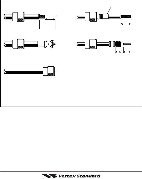
5.3 COAXIAL CABLE
VHF antennas are connected to the transceiver by means of a coaxial cable – a shielded transmission line. Coaxial cable is specified by it’s diameter and construction.
For runs less than 20 feet, RG-58/U, about 1/4 inch in diameter is a good choice. For runs over 20 feet but less than 50 feet, the larger RG-8X or RG-213/U should be used for cable runs over 50 feet RG-8X should be used. For installation of the connector onto the coaxial cable refer to the figure below.
Adapter


 1/16''
 3/4''
3/4''

 3/4'' 1 1/8''


 1/8''
1/8''
3/8'' 5/8''
To get your coax cable through a fitting and into your boat’s interior, you may have to cut off the end plug and reattach it later. You can do this if you follow the directions that come with the connector. Be sure to make good soldered connections.
VM-3500E |
Page 7 |
6 INSTALLATION
6.1 LOCATION
The radio can be mounted at any angle. Choose a mounting location that:
•is far enough from any compass to avoid any deviation in compass reading due to the speaker magnet
•provides accessibility to the front panel controls
•allows connection to a power source and an antenna
•has nearby space for installation of a microphone hanger
•the antenna must be mounted at least 3 feet from radio
Note: To insure the radio does not affect the compass or radios performance is not affected by the antenna location, temporarily connect the radio in the desired location and:
a.Examine the compass to see if the radio causes any deviation
b.Connect the antenna and key the radio. Check to ensure the radio is operating correctly by requesting a radio check.
6.2ELECTRICAL CONNECTIONS
CAUTION
Reverse polarity connections will damage the radio!
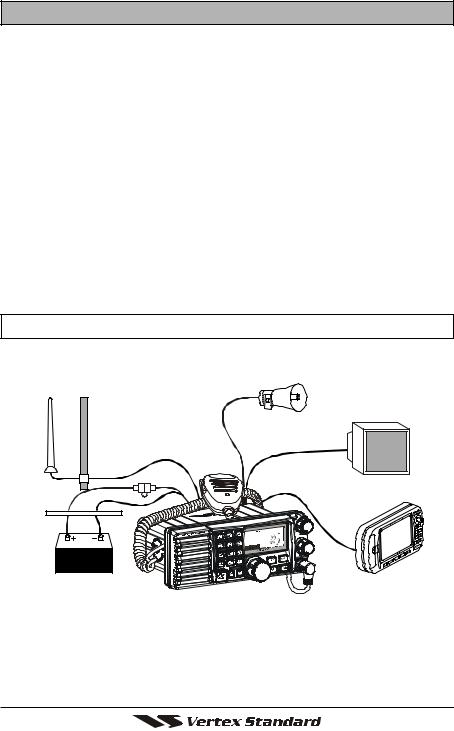
Connect the power cord and antenna to the radio. Antenna and Power Supply connections are as follows (see Figure 1):
Optional HAIL/PA Horn
Antenna
Optional Speaker
Water proof
Deck Outlet
Fuse
Accessory Cable
Red Black
Power Source
GPS Navigation Receiver
Figure 1. General Installation
1.Mount the antenna at least 3 feet away from the radio. At the rear of the radio, connect the antenna cable. It must have a PL259 connector. RG-8/U coaxial cable must be used if the antenna is 25 feet or more from the radio.
RG58 cable can be used for distances less than 25 feet.
Page 8 |
VM-3500E |
2.Connect the red power wire to a 13.8 VDC ±20% power source. Connect the black power wire to a negative ground.
3.If an optional remote extension speaker is to be used, refer to next section for connections.
4.It is advisable to have a Certified Marine Technician check the power output and the standing wave ratio of the antenna after installation.
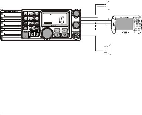
6.3 ACCESSORY CABLE
White: External speaker (+) Shield: External speaker (–)
Red: PA speaker (+)
Shield: PA speaker (–)
Blue: NMEA IN (+) from GPS navigation receiver
Green: NMEA IN (–) from GPS navigation receiver
Gray: NMEA OUT (+) to GPS navigation receiver Brown: NMEA OUT (–) to GPS navigation receiver
When connecting the external speaker or GPS navigation receiver, strip off about 1 inch (2.5 cm) of the specified wire’s insulation, then splice the ends together using proper waterproofing techniques.
-/*
JKL
DISTRESS
PULL OPEN
PA Speaker
Shield |
|
Red |
|
Blue |
NMEA OUT ( ) |
Green |
NMEA OUT ( ) |
Gray |
NMEA IN ( ) |
Brown |
NMEA IN ( ) |
Shield |
|
White |
|
GPS Receiver
External Speaker
Wire Color/Description |
Connection Examples |
WHITE - External Speaker (+) |
Connect to external 4 Ohm audio speaker |
SHIELD - External Speaker (–) |
Connect to external 4 Ohm audio speaker |
RED - PA Speaker (+) |
Connect to external 4 Ohm PA speaker |
SHIELD - PA Speaker (–) |
Connect to external 4 Ohm PA speaker |
BLUENMEA Input (+) |
Connect to NMEA (+) output of GPS |
GREEN - NMEA Input (–) |
Connect to NMEA (–) output of GPS |
GRAYNMEA Output (+) |
Connect to NMEA (+) input of GPS |
BROWN-NMEA Output (–) |
Connect to NMEA (–) input of GPS |
VM-3500E 
 Page 9

6.4 CONNECTION OF GPS WITH NMEA OUTPUT
•The GPS must have the NMEA Output turned on and set to 4800 Baud in the setup menu. If there is a selection for parity select none.
•For further information on interfacing /setting up your GPS. Please contact the manufacturer of the GPS receiver.
•VM-3500E can read NMEA-0183 version 2.0 or higher.
•The NMEA supported sentences are:
Input: GLL, GGA, RMC and GNS (RMC sentence is recommended) Output:DSC and DSE
(DSC sentences to Standard Horizon Plotter for Position Polling)
6.5 CHECKING GPS CONNECTIONS
After connections have been made between the VM-3500E and the GPS, a small satellite icon will appear on the top right corner of
the LCD display. To see additional GPS information, press the [F] key momentarily, then press the [6(NAV)] key. The VM-3500E shows the Date, Time, SOG and COG.
Page 10 |
VM-3500E |
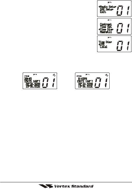
6.6 CHANGING THE GPS TIME
From the Factory the VM-3500E shows GPS satellite time or UTC time. A time offset is needed to show the local time in your area.
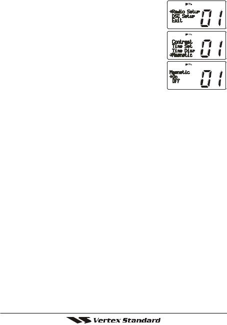
1. Press and hold down the [CALL] key until “Radio
Setup” menu appears.
2. Press the [ENT] key, then select “Time Set” with the
CHANNEL selector knob.
3. Press the [ENT] key.
4. Turn the CHANNEL selector knob to select time offset from UTC. See illustration below to find your offset time from UTC. If “0:00” is assigned, the time is the same as UTC (Universal Time Coordinated or
GMT Greenwich Mean Time).
5.Press the [ENT] key to store the time offset.
6.Press the [16/9] key or turn the CHANNEL selector knob to select “Exit,” then press the [ENT] key to return to the “Radio Setup” menu, select “Exit” and press the [ENT] key to return to radio operation.
OFFSET TIME TABLE
VM-3500E |
Page 11 |
6.7 CHANGING THE TIME LOCATION
You may select the time display between local time and UTC (time GPS sends to radio). Time is displayed when GPS position (LAT/LON) is displayed by pressing the [F] key followed by the [6(NAV)] key.
1. Press and hold down the [CALL/SET(MENU)] key until “Radio Setup” menu appears.
2. Press the [ENT] key, then select “Time Disp.” in the
“Radio Setup” menu with the CHANNEL selector knob.
3. Press the [ENT] key.
4. Turn the CHANNEL selector knob to select “UTC” or “Local.”
5. Press the [ENT] key to store the selected setting.
6. To exit this menu and return to radio operation mode press the [16/9] key.
In the local time mode, the display shows the time by the 12-hour system.
Meanwhile, the display shows the time by the 24-hour system in the UTC mode.
(“UTC” mode) |
(“LOCAL” mode) |
Page 12 |
VM-3500E |
6.8 CHANGING COG TO TRUE OR MAGNETIC
Allows customizing the NAV data showing GPS Course Over Ground (COG). Factory default is True however following the steps below the COG can be changed to Magnetic.
1. Press and hold down the [ENT] key until “Radio Setup” menu appears.
2. Press the [ENT] key, then select “Magnetic” with the
CHANNEL selector knob. 3. Press the [ENT] key.
4. Turn the CHANNEL selector knob to select “On” (representing “Magnetic”) or “Off” (representing “True”).
5. Press the [ENT] key to store the selected setting.
6. Turn the CHANNEL selector knob to select “Exit,” then press the [ENT] key to return to the “Radio Setup” menu, select “Exit” and press the [ENT] key to return to radio operation.
VM-3500E |
Page 13 |
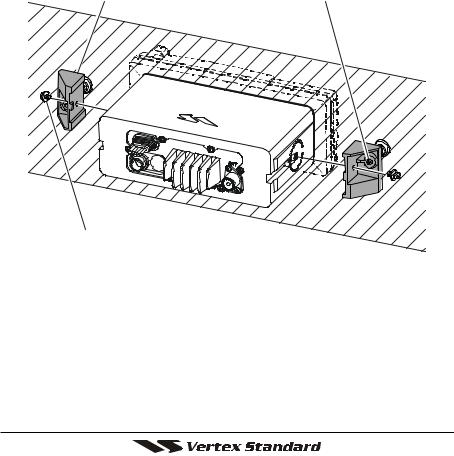
6.9 OPTIONAL MMB-84 FLUSH MOUNT INSTALLATION
1.To assist in flush mounting, a template has been included. Use this template to find the mounting location.
2.Use the template to mark the location where the rectangular hole is to be cut. Confirm the space behind the dash or panel is deep enough to accommodate the transceiver (at least 15 cm deep).
There should be at least 1 cm between the transceiver’s heatsink and any wiring, cables or structures.
3.Cut out the rectangular hole and insert the transceiver.
4.Fasten the brackets to the sides of the transceiver with the lock washer nut combination; so that the mounting screw base faces the mounting surface (see Figure 2).
5.Turn the adjusting screw to adjust the tension so that the transceiver is tight against the mounting surface.
Bracket |
Adjusting Screw |
Lock-washer nut combination
Figure 2. MMB-84 Flush Mount Installation
Page 14 |
VM-3500E |
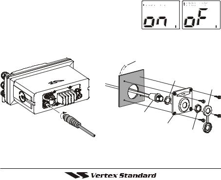
6.10 OPTIONAL ENHANCED RAM+ SECOND STATION MIC INSTALLATION
The VM-3500E is capable of using an Enhanced RAM+ MIC to remotely control the Radio, DSC and PA/Fog functions. In addition the VM-3500E can operate as a full function intercom system.
1.Connect the RAM+ MIC Cable to the RAM MIC CONNECTOR on the rear panel, then tighten the Cable Nut (See Figure 3).
2.Referring to Figure 3, make a 30 mm hole in the wall, then insert the RAM+
MIC Cable into this hole. Connect the Gasket and Mount Base to the RAM+ MIC Cable Connector using the Nut.
3.Drill the four Screw holes (approx. 2 mm) on the wall, then install the Mounting
Base to the wall using four screws.
4.Put the Rubber Cap on to the Nut. The installation is now complete.
5.Wires for a external speaker are privided on the RAM+ mic cable. Connect any 8 Ohm extenal speaker. When connected the RAM+ controls the volume level of this speaker.
RAM+ or External Speaker Selection
By default the RAM+ internal speaker is turned on, however using the RAM+ mic this speaker can be turned off so the extenal speaker can be used.
1. Press and hold the [CALL/SET] key on the RAM+ Mic. 2. Using the [ ] or [ ] keys to select “RAM 


SPK” and press the [CALL/SET] key.
3. Press the [ ] or [ ] key to turn the RAM+ Speaker “oF.”
4. Press the [16/9] key to exit this mode.
EXP SP Cable for the RAM+ MIC
Wall
Gasket
Cap
RAM MIC Cable
Mounting Bracket
Nut
Figure 3. Enhanced RAM+ MIC Installation
VM-3500E |
Page 15 |

7 CONTROLS AND INDICATORS
NOTE
This section defines each control of the transceiver. See Figure 4 for location of controls. For detailed operating instructions refer to chapter 8 of this manual.
 VOLUME CONTROL (VOL)
Adjusting this control clockwise, increases the audio volume level.
 SQUELCH CONTROL (SQL)
Adjusting this control clockwise, sets the point at which random noise on the channel does not activate the audio circuits but a received signal does. This point is called the squelch threshold. Further adjustment of the squelch control will degrade reception of wanted transmissions.
 MICROPHONE CONNECTOR
Connect the supplied MH-63A6 Hand Microphone to this jack.
 KEY BUTTON
[16/9] Key
Immediately recalls channel 16 from any channel location. Holding down this key recalls channel 9. Pressing the [16/9] key again reverts to the previous selected working channel.
Secondary use (Depends on the transceiver version)
Press and hold the [16/9] key then press the [WX] key to switch the Channel Group.
[WX] Key
Immediately recalls the previously selected NOAA weather channel from any channel.
Secondary use (Depends on the transceiver version)
Holding down the [16/9] key while pressing the [WX] key changes the Channel Group.
[H/L] Key
Toggles between 25 W (High) and 1 W (Low) power. When the [H/L] key is pressed while the transceiver is on channel 13 or 67, the power will temporarily switch from LO to HI power until the PTT is released.
The [H/L] key does not function on transmit inhibited and low power only channels.
Page 16 |
VM-3500E |

-/*
JKL
DISTRESS
PULL OPEN
Figure 4. Controls and Connectors
VM-3500E |
Page 17 |

[PWR] Key
Turns the transceiver on and off. To turn the transceiver on, press and hold this key until the LCD turns on. To turn it off, press and hold this key until the LCD turns off. When the power is turned on, the transceiver is set to the last selected channel.
 CHANNEL SELECTOR KNOB
Rotary knob used to select channels and to choose menu items (such as the DSC menu, radio setup menu, and DSC setup menu). The [UP( )] /
[DOWN( )] keys on the microphone can also be used to select channels and menu items.
When the PA/FOG mode is activated, the CHANNEL selector knob adjust the audio output level.
Secondary Use (Depends on the transceiver version)
While holding down the [SCAN] key and turning the CHANNEL selector knob, you can confirm memory channels for scanning.
 KEYPAD
[1(DIM)] Key
When in radio mode, this key is used to directly select channel digit “1” in a channel number.
Secondary use
Press the [F] key first then press the [1(DIM)] key, access the LCD Dimmer menu. Refer to section “8.15 LCD DIMMER” for details.
[2(MEM)] Key
When in radio mode, this key is used to directly select channel digit “2” in a channel number.
Secondary use (Depends on the transceiver version)
Press the [F] key first then press the [2(MEM)] key, memorize the selected channel into the transceiver scan memory for scanning. When repeat the same procedures ([F] [2(MEM)]), DELETES the channel from the scan memory. Refer to section “8.12 SCANNING” for details.
[3(SCAN)] Key
When in radio mode, this key is used to directly select channel digit “3” in a channel number.
Secondary use (Depends on the transceiver version)
Press the [F] key first then press the [3(SCAN)] key, start and stop the scanning of programmed channels. Refer to section “8.12 SCANNING” for details.
Page 18 |
VM-3500E |

[4(DW)] Key
When in radio mode, this key is used to directly select channel digit “4” in a channel number.
Secondary use (Depends on the transceiver version)
Press the [F] key first then press the [4(DW)] key, scan for voice communications on the priority channel and another selected channel until a signal is received on either channel (Dual Watch). Refer to section “8.11 DUAL WATCH (TO PRIORITY CHANNEL)” for details.
[5(IC)] Key
When in radio mode, this key is used to directly select channel digit “5” in a channel number.
Secondary use
Press the [F] key first then press the [5(IC)] key, when the optional RAM+ Mic is connected, intercom operation will operate between radio and
RAM+ Mic. Refer to section “8.16 INTERCOM OPERATION” for details.
[6(NAV)] Key
When in radio mode, this key is used to directly select channel digit “6” in a channel number.
Secondary use
Press the [F] key first then press the [6(NAV)] key, the LCD displays NAV GPS Data, Time, SOG (Speed Over Ground), and COG (Course Over
Ground) when a GPS is connected to the accessory cable of the VM-
3500E. See section “8.4 CONNECTION OF GPS WITH NMEA OUTPUT” for details.
[7(SCRM)] Key
When in radio mode, this key is used to directly select channel digit “7” in a channel number.
Secondary use
Press the [F] key first then press the [7(SCRM)] key, when the optional
CVS2500 Voice Scrambler Unit is installed, available to operate the Voice Scrambler function. Refer to section “8.17 VOICE SCRAMBLER” for details.
[8(PA)] Key
When in radio mode, this key is used to directly select channel digit “8” in a channel number.
Secondary use
Press the [F] key first then press the [8(PA)] key, available to operate the 30 Watt PA function. Refer to section “8.13 PA/FOG OPERATION” for details.
VM-3500E |
Page 19 |
[9(FOG)] Key
When in radio mode, this key is used to directly select channel digit “9” in a channel number.
Secondary use
Press the [F] key first then press the [9(FOG)] key, available to operate the Fog Horn function. Refer to section “8.13 PA/FOG OPERATION” for details.
[0] Key
When in radio mode, this key is used to directly select channel digit “0” in a channel number.
[CLR] Key
Press the [CLR] Key to cancel the menu selection and/or keypad entry.
[ENT] Key
Press the [ENT] Key to determine the menu selection and/or keypad entry.
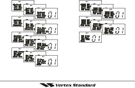
[CALL(MENU)] Key
Press the [CALL(MENU)] key to access the DSC OPERATION menu. The “INDIVIDUAL CALL,” “GROUP CALL,” and “ALL SHIPS CALL” functions can be accessed from the DSC OPERATION menu.
Secondary use
Press and hold the [CALL(MENU)] key to access the “Radio Setup”
(refer to Section 10) or “DSC Setup” menu (refer to Section 8).
“Radio Setup” menu |
“DSC Setup” menu |
[F] Key
Press the [F] key to activate the “Alternate” key function.
Page 20 |
VM-3500E |
 [DISTRESS] Key
Used to send a DSC Distress Call. To send the distress call refer to section
“9.3.1 (Transmitting A DSC Distress Call).”
 ACCESSORY CONNECTION CABLE
Connects the VM-3500E to a GPS, a PA speaker, and an external speaker.
 DC INPUT CABLE
Connects the radio to a DC power supply capable of delivering 12V DC.
 RAM+ MIC CONNECTORS
Connects the VM-3500E to the enhanced RAM+ MIC (Remote Access Microphone). Refer to section “11 ENHANCED RAM+ MIC OPERATION” for detailes.
 ANTENNA JACK
Connects an antenna to the transceiver. Use a marine VHF antenna with an impedance of 50 ohms.
Warning!: The 50 V RF voltage (@25 W/50 Ω) is applied to the TX


 RF section of the transceiver while transmitting.
Do not touch the TX RF section absolutely while transmitting.
 PTT (Push-To-Talk) SWITCH
Keys the transmitter when the transceiver is in radio mode. If the transceiver is in the intercom operation mode (between the RAM+ and the VM-3500E), or PA mode, it activates the VM-3500E microphone for voice communications.
 MICROPHONE
Transmits the voice message with reduction of background noise, using Clear Voice Noise Reduction Technology.
 MICROPHONE SPEAKER
The audio heard through internal radio speaker is heard through microphone speaker.
 [UP( )] / [DOWN( )] KEYS
The [UP( )] and [DOWN( )] on the microphone function the same as the
CHANNEL selector knob on the front panel of the transceiver.
 [16/9] Key
Pressing the [16/9] key immediately recalls channel 16 from any location.
Press and hold the [16/9] key to recall channel 9. Pressing the [16/9] key again will revert the radio to the previous selected channel.
VM-3500E |
Page 21 |
 Loading...