

Vermont Castings 2460 Instruction Manual

Convection
Heater Model
2460, 2461,
2462
7001135 1/07 Rev. 19
Homeowner’s Installation and Operating Manual
DO NOT DISCARD THIS MANUAL: Retain for future use
If this heater is not properly installed, operated, and maintained, a house fire may result.
For safety, follow all installation, operation and maintenance directions. Contact local
building officials about restrictions and installation inspection requirements in your
area.
SAFETY NOTICE

2
Dutchwest
7001135
PLEASE NOTE
Please read this entire manual berfore you install
and use your new room heater. Failure to follow
instructins my result in property damage, bodily
injury or loss of life. Save these instructions for
future use.
The Dutchwest models covered in this Owner’s Guide have been tested and
listed by Inchcape Testing Services / Warnock Hersey of Middleton, Wisconsin. The test standards utilized were ANSI/UL 1482 for the United States and
CAN/CGA - B366.2 for Canada. Dutchwest models are not listed for mobile
home installations.
Patents: U.S. - D288357, 4502395, 4646712;
Canada - 1235969. Other foreign mechanical patents issued.
Accessories
• Bottom Heat Shield
• Clearance-reducing Rear Heat Shields
• Clearance-reducing Heat Shields for single-wall
stove pipe
• 2” legs
• Warming shelves (Small and Large Heaters only)
• Two-speed convection blower
• Automatic thermostat for the blower
Table of Contents
Specifications ............................................................ 3
Installation ..........................................................4
Clearances
.......................................................12
Assembly ..........................................................16
Operation
..........................................................17
Maintenance
.....................................................22
Illustrated Parts List ..........................................30
Proposition 65 Warning: Fuels used in gas, woodburning or oil fired appliances, and the products of
combustion of such fuels, contain chemicals known
to the State of California to cause cancer, birth defects and other reproductive harm.
California Health & Safety Code Sec. 25249.6

3
Dutchwest
7001135
1. Maximum burn times and heat outputs are based on laboratory testing using full loads of seasoned hardwoods, and may vary in individual use
depending on how the stove is operated, type and moisture content of fuels, and other factors. Maximum burn times are achieved under different
operating conditions than are maximum heat outputs.
2. These values are based on operation in building code-conforming homes under typical Winter climate conditions in the northeastern U.S. If your
home is of nonstandard construction (e.g. unusually well-insulated, not insulated, built underground, or if you live in a more severe or more temperate climate), these figures may not apply. Since so many variables affect performance, consult your Dutchwest Authorized Dealer to determine
realistic expectations for your home.
4. Under specific conditions used during EPA emissions testing.
5. Based on preliminary results obtained during EPA emissions testing.
Specifications
A
C
B
D
G
F
E
Fig. 1 Dutchwest Convection Heater specifications.
Stove Model Number 2460 2461 2462
A 22” (560 mm) 25³⁄₄” (654 mm) 28¹⁄₄” (717 mm)
B 21” (530 mm) 24¹⁄₂” (620 mm) 27” (690 mm)
C 29³⁄₄” (754 mm) 30” (760 mm) 33” (840 mm)
D 16” (410 mm) 16” (410 mm) 18¹⁄₄” (467 mm)
E 14³⁄₄” (375 mm) 14⁵⁄₈” (380 mm) 17” (430 mm)
F 26³⁄₄” (683 mm) 27” (690 mm) 30¹⁄₈” (763 mm)
G 29³⁄₄” (754 mm) 30” (760 mm) 33” (840 mm)
Log length: 19” (480 mm) 22” (560 mm) 25” (640 mm)
Maximum burn time1: 8 hrs. 9 hrs. 12 hrs.
Average area heated (sq. ft.)2: 700-1,400 (65-130m2) 800-1,600 (75-150m2) 1,200-2,400 (112-224m2)
Range of heat output4: 7,800 - 26,800 Btu/hr. 11,300 - 26,800 Btu/hr. 10,500-27,700 Btu/hr
5
Maximum heat output: 35,000 Btu/hr. 40,000 Btu/hr. 55,000 Btu/hr.
EPA emissions rating4 (g/h, catalytic): 1.1 1.4 1.3
Weight: 380 lbs. (172 kg) 436 lbs. (198 kg) 634 lbs. (288 kg)
Loading: Side or front Side or front Side or front
Flue exit position (reversible): Top or rear Top or rear Top or rear
Air controls: 2 controls 2 controls 2 controls
4
Dutchwest
7001135
Installation
SAFETY NOTICE: IF YOUR DUTCHWEST CONVECTION HEATER IS NOT PROPERLY INSTALLED,
OPERATED AND MAINTAINED, A HOUSE FIRE MAY
RESULT. FOR SAFETY, FOLLOW ALL INSTALLATION, OPERATION AND MAINTENANCE DIRECTIONS. CONTACT LOCAL BUILDING OFFICIALS
ABOUT RESTRICTIONS AND INSTALLATION
INSPECTION REQUIREMENTS IN YOUR AREA.
Before you begin the installation, review your plans to
confirm that:
• Your stove and chimney connector will be far enough
from combustible material to meet all clearance requirements.
• The floor protector is large enough and is constructed
properly to meet all requirements.
• You have obtained all necessary permits from local
authorities.
Your local building official is the final authority for approving your installation as safe and for determining
that it meets local and state codes.
Clearance and installation information is printed on the
metal label attached to the rear of the stove. Local authorities generally will accept the label as evidence that,
when the stove is installed according to the information
on the label and in this manual, the installation meets
codes and can be approved.
Codes vary in different areas, however. Before starting
the installation, review your plans with the local building
authority. Your local dealer can provide any additional
information needed.
Important: Failure to follow these installation instructions may result in a dangerous situation, including a
chimney or house fire. Follow all instructions exactly,
and do not allow makeshift compromises to endanger
property and personal safety.
Chimney Types
Your Dutchwest Convection Heater must be connected
to a sound masonry chimney that meets local codes, a
relined masonry chimney that meets local codes, or to
an approved prefabricated metal chimney. Whatever
kind you use, the chimney and chimney connector must
be in good condition and kept clean.
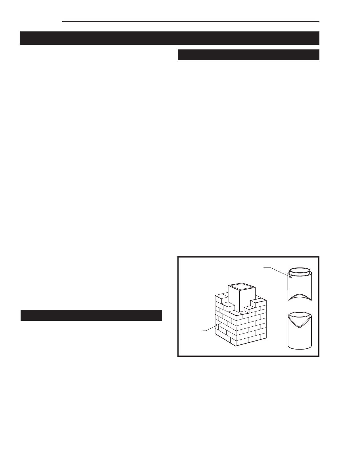
Masonry Chimneys
If you use an existing masonry chimney, it must be
inspected to ensure safe condition before the stove
is installed. Your local professional chimney sweep,
building inspector, or fire department official will be able
either to make the inspection or to direct you to someone who can.
An inspection of the chimney must confirm that it has
a lining. Do not use an unlined chimney. The chimney should also be examined for cracks, loose mortar,
other signs of deterioration, and blockage. Repair any
defects before the chimney is used with your stove.
Unused openings in an existing masonry chimney must
be sealed with masonry to the thickness of the chimney
wall, and the chimney liner should be repaired. Openings sealed with pie plates or wallpaper are a hazard
and should be sealed with mortar or refractory cement.
In the event of a chimney fire, flames and smoke may
be forced out of these unused thimbles.
The chimney should be thoroughly cleaned before use.
A newly-built masonry chimney must conform to the
standards of your local building code or, in the absence
of a local code, to a recognized national code. Masonry
chimneys must be lined, either with code-approved
masonry or pre-cast refractory tiles, stainless steel
pipe, or a code-approved, “poured-in-place” liner. The
chimney’s clean-out door must seal tightly.
Prefabricated Double-Wall
Insulated Chimney
Tile Lined
Masonry
Chimney
ST241
Fig. 2 If in sound condition and approved for use, either a
masonry or a prefabricated chimney may be used.

5
Dutchwest
7001135
Prefabricated Chimneys
A prefabricated metal chimney must be one tested and
listed for use with solid-fuel burning appliances.
A horizontal connector run should be inclined 1/4” per
foot (20 mm per meter) from the stove toward the
chimney. The recommended maximum length of a horizontal run is 3 feet (1m) and the total length of chimney
connector should be no longer than 8 feet (2.5m).
Chimney Height
For proper draft and good performance, the chimney
should extend at least 16’ (5 m) above the flue collar of
the stove.
The chimney must also extend at least 3’ (900 mm)
above the highest point where it passes through a roof,
and at least 2’ (600 mm) higher than any portion of a
building within 10’ (3 m). (Fig. 2)
DO NOT CONNECT THIS UNIT TO A CHIMNEY
FLUE SERVING ANOTHER APPLIANCE.
Chimney Size
The Model 2460 and 2461 heaters should be vented
into a masonry chimney with a square flue with nominal flue size of 8” x 8” (200 x 200 mm), or a round flue
with nominal flue size of 6” (150 mm). The Model 2462
heater should be vented into a masonry chimney with a
nominal flue size of 8” x 8” (200 mm x 200 mm) square,
or 8” (200 mm) round.
Chimney liners larger than 8” x 12” (200 x 300 mm)
may promote rapid cooling of smoke and reduction in
draft, especially if they are located outside the home.
These large chimneys may need to be insulated or
have their flues relined for proper stove performance.
Accessories to help make the connection between
stainless steel chimney liners and the stove are available through your local dealer.
2' MIN.
2' MIN.
3'
MIN.
0 TO 10'
3'
MIN.
0 TO 10'
Reference
Point
AC246
Fig. 3 The 2/3/10 rule for chimneys.
Guidelines for Installing
the Chimney Connector
The chimney connector is the single-wall pipe, or listed
and approved double-wall pipe that connects the stove
to the chimney. The chimney itself is a masonry or
prefabricated structure that encloses the flue. Chimney
connectors are used only to make the connection from
the stove to the chimney.
Do not pass the chimney connector through a combustible wall or ceiling, or through an attic, a closet or any
similar concealed space. If passage through a combustible wall is unavoidable, follow the recommendations in
the following section on Wall Pass-Throughs. Keep the
passage as short and direct as possible, with no more
than two 90 degree turns.
Two Types of Connector
You may use either a single-wall steel connector of the
size and gauge described below, or a listed and approved double-wall connector.
Single-Wall Connector
The single-wall chimney connector should be made of
24 gauge or heavier steel, and must have a minimum
internal diameter of 6” (150 mm) for models 2460 and
2461, or 8” (200 mm) for model 2462.
Install single-wall chimney connector not less than 18”
(450 mm) from the ceiling.
In cathedral ceiling installations, extend the prefabricated chimney downward to within 8 feet (2.5 meters)
of the stove. The entire chimney connector should be
exposed and accessible for inspection and cleaning.
Do not use galvanized chimney connector; it cannot
withstand the high temperatures that can be reached
by smoke and exhaust gases and it may release toxic
fumes under high heat.
Chimney
Elbow
Slip Pipe
Standard Connector
Flue Liner
Flue
Thimble
Flue Collar
Floor Protector
ST418
Fig. 4 Sections of a steel chimney connector of at least 24
gauge thickness are fastened together with screws to
connect the stove to the chimney.

6
Dutchwest
7001135
Double-Wall Connector
Information on assembling and installing double-wall
connectors is provided by the manufacturer of the
double-wall pipe. Follow the manufacturer’s installation
instructions exactly. Most manufacturers of prefabricated double-wall insulated chimneys also offer doublewall connector pipes. Using a chimney and connector
pipe from the same manufacturer helps simplify the
assembly and installation.
NOTE: For installations using double-wall connectors, minimum clearances must conform to listed
clearances in the Stove and Chimney Connector
Clearance Charts on page 12 and 13 of this manual.
Assembling Single-Wall
Chimney Connector
SAFETY NOTE: Always wear gloves and safety
goggles when drilling, cutting or joining sections of
chimney connector.
For double-wall connectors, follow the manufacturer’s
instructions exactly. For single-wall connectors, follow
the instructions below.
1. Insert the crimped end of the first section into the
stove’s flue collar, and keep each crimped end pointing
toward the stove (Fig.5). Using the holes in the flue collar as guides, drill 1/8” (3 mm) holes in the bottom of the
first section of chimney connector and secure it to the
flue collar with three #10 x 1/2” sheet metal screws.
Toward
Stove
Flue Gas
Direction
ST242
Fig. 5 Crimped sections always point toward the stove so
that any liquid condensation will not leak out.
2. Secure each joint between sections of chimney connector, including telescoping joints, with at least three
sheet metal screws.
3. Secure the chimney connector to the chimney. Instructions for various installations follow below.
4. Confirm that the installed stove and chimney con-
nector are correct distances from nearby combustible
material. See the clearance charts on pages 12 and 13.
NOTE: Special slip pipes and thimble sleeves that form
telescoping joints between sections of chimney connector are available to simplify installations. They can
eliminate the need to cut individual connector sections.
Consult your local dealer about these special pieces.
Securing the Connector
to a Prefabricated Chimney
Follow the installation instructions of the chimney
manufacturer exactly as you install the chimney. The
manufacturer of the chimney will supply the accessories to support the chimney, either from the roof of
the house, at the ceiling of the room where the stove is
installed, or from an exterior wall.
Special adaptors are available from your local dealer
to make the connection between the prefabricated
chimney and the chimney connector. (Fig. 6) The top
of such adaptors attach directly to the chimney or to the
chimney’s ceiling support package, while the bottom of
the adaptor is screwed to the chimney connector.
These adaptors are designed so the top end will fit
outside the inner wall of the chimney, and the bottom
end will fit inside the first section of chimney connector.
Any soot or creosote falling from the inner walls of the
chimney will stay inside the chimney connector.
Prefab (Insulated)
Chimney
Ceiling Support
Package
Prefab Chimney
Adapter
Chimney Connector
(Stovepipe)
ST419
Fig. 6 Joining the chimney connector to a prefabricated
chimney.

7
Dutchwest
7001135
Securing the Connector
to a Masonry Chimney
The Dutchwest Convection heaters may be connected
to either a freestanding masonry chimney or a masonry
fireplace chimney.
Freestanding Installations
If the chimney connector must pass through a combustible wall to reach the chimney, follow the recommendations in the wall pass-through section that follows.
The opening through the chimney wall to the flue
(the “breech”) must be lined with either a ceramic or
metal cylinder, called the “thimble”, which is securely
cemented in place. (Fig. 7) Most chimney breeches
incorporate thimbles, but check to be sure the fit is snug
and the joint between thimble and chimney wall firmly
cemented.
A special piece called the “thimble sleeve,” slightly
smaller in diameter than the standard connector and
most thimbles, will ease the removal of the chimney
connector system for inspection and cleaning. Thimble
sleeves should be available from your local dealer.
To install a thimble sleeve, slide it into the breech until
it is flush with the inner flue wall. Don’t extend it into
the actual flue passage, as that could interfere with the
draft.
The thimble sleeve should protrude 1-2” (25-50 mm)
into the room. Use furnace cement and thin gasketing
to seal the sleeve in place in the thimble. Secure the
chimney connector to the outer end of the sleeve with
sheet metal screws.
Fireplace Installations -
Above the Fireplace
In this installation, the chimney connector rises from
the stove, turns ninety degrees, and goes back into the
fireplace chimney. The liner of the fireplace chimney
should extend at least to the point at which the chimney
connector enters the chimney. Follow all the guidelines
for installing a chimney connector into a freestanding
masonry chimney, and pay special attention to these
additional points:
• Check the stove and chimney connector clearances
to combustible mantel or trim materials. Use the
necessary combination of mantel, trim, and connector heat shields to provide the required clearances.
(Fig. 8)
• Double-check connector clearance from the ceiling.
• The fireplace damper must be closed and sealed
to prevent room air from being drawn up the flue,
reducing the draft. However, it must be possible to
re-open the damper to inspect or clean the chimney.
Flue Liner
Extend Chimney Connector to the First
Tile of
the Flue Liner
Observe
Miniumum Clearances
Damper
Plate is
Remvoed
or Locked
in Open
Position
Close Of
f
the Damper
Opening with
Sheet Metal
and Sealant
ST245a
Fig. 9 The connector passes through the fireplace to enter
flue. Special Fireplace Adapter Kits to simplify fireplace installations are available from your local dealer.
Masonry Wall
Ceramic Flue Liner
Chimney Connector Shield
Block-Of
f Plate
Chimney Connector
ST244a
Fig. 8 The connector enters flue above the fireplace. If the
clearance between the chimney connector and either the
mantel and/or the ceiling is inadequate, special protective
shields will be required.
Thimble
Sleeve
Elbow
Flue
Keep
Sleeve
End Flush
with Flue
Tile
Thimble
Flue Liner
Chimney
Connector
ST243
Fig. 7 The thimble, made of either ceramic or metal, must be
cemented in place securely.

8
Dutchwest
7001135
Fireplace Installations -
Through the Fireplace
The Convection heaters may be installed either without
legs* as a fireplace insert, or with standard legs attached - depending on the safety regulations that apply
to your situation, the height of the fireplace opening and
your own preference. For either situation, the chimney
connector/positive connection kit extends back from the
stove, enters the fireplace cavity, and turns upward. It
then passes through the fireplace damper opening and
smoke chamber and connects to the chimney flue.
In such installations, a “positive connection” must be
made to the chimney flue with a special kit available
from your local dealer. Also, special clearance and floor
protection provisions must be observed. These provisions are discussed in the Clearance and Floor Protection sections respectively.
Wall Pass-Throughs
Whenever possible, design your installation so the connector does not pass through a combustible wall. If you
must use a wall pass-through in your installation, check
with your building inspector before you begin and construct it in accordance with local building codes. Also
check with the chimney connector manufacturer for any
specific requirements.
Accessories are available for use as wall passthroughs. If using one of these, make sure it has been
tested and listed for use as a wall pass-through.
All combustible material in the wall is cut away a sufficient distance from the single-wall connector to provide
the required 12” (305 mm) clearance for the connector.
Any material used to close up the opening must be noncombustible.
The following wall pass-through methods may be approved in your area:
• Use a section of listed factory-built chimney with a
nine-inch clearance to combustibles.
• Place a chimney connector pipe inside a ventilated
thimble, which is then separated from combustibles
by six inches (152 mm) of fiberglass insulating material.
• If the stove is installed without legs, we recommend
the use of noncombustible tiles or pavers as shims
to allow air flow into the convection air inlets under
the stove. Make sure not to block air slots instove
bottom with shims or remove fan cover.
• Place a chimney connector pipe inside a section of
listed solid-insulated, factory-built chimney, with an
inside diameter 2 inches (51 mm) larger than the
chimney connector and having 1 inch (25.4 mm) or
more of insulation and maintaining a minimum 2 inch
air space between the outer wall of the chimney and
combustibles.
In Canada: The Canadian Standards Association has
established different guidelines. Figure 11 shows one
method, in which all combustible material in the wall is
cut away to provide the required 18” (450 mm) clearance for the connector. The resulting space must
remain empty.
DO NOT CONNECT THE HEATER TO ANY AIR
DISTRIBUTION DUCT OR SYSTEM.
18”
(450mm)
Empty Space
All Around
the Chimney
Connector
Sheet Metal
Cover
(One side
only)
ST421
Fig. 11 Hollow wall pass-through.
Chimney Connector
12”
(305mm)
12”
(305mm)
ST420
Fig. 10 Wall pass-through enclosed with noncombustible
materials.
9
Dutchwest
7001135
A flush-mounted sheet metal cover may be used on one
side only. If covers must be used on both sides, each
cover must be mounted on non-combustible spacers
at least 1” (25 mm) clear of the wall. Your Dutchwest
dealer or your local building inspector can provide details of other approved methods of passing a chimney
connector through a combustible wall. In Canada, this
type of installation must conform to CAN/CSA-B365,
Installation Code for Solid Fuel Burning Appliances and
Equipment.
NOTE: Do not vent your Dutchwest stove into a factorybuilt (zero-clearance) fireplace. These appliances and
their chimneys are specifically designed as a unit for
use as fireplaces. It may void the listing or be hazardous to adapt them for any other use.
Floor Protection
A tremendous amount of heat radiates from the bottom
plate of your Dutchwest stove. The floor area directly
under and around the stove will require protection from
radiant heat as well as from stray sparks or embers that
may escape the firebox.
Heat protection is provided through the use of a CFM
Corporation Bottom Heat Shield. Spark and ember
protection must be provided by a floor protector constructed with noncombustible material as specified.
Most installations will require that the bottom heat
shield be attached. Only when the stove is placed on a
completely noncombustible surface such as unpainted
concrete over earth may it be used without the heat
shield.
Even when the bottom heat shield is installed, you must
provide special protection to the floor beneath. For
installation with the heat shield attached, use a noncombustible floor protector such as 1/4” non-asbestos
mineral board or equivalent, or 24 gauge sheet metal.
The floor protector may be covered with a decorative
noncombustible material if desired. Do not obstruct the
space under the heater.
Protection requirements vary somewhat between the
United States and Canada as follows:
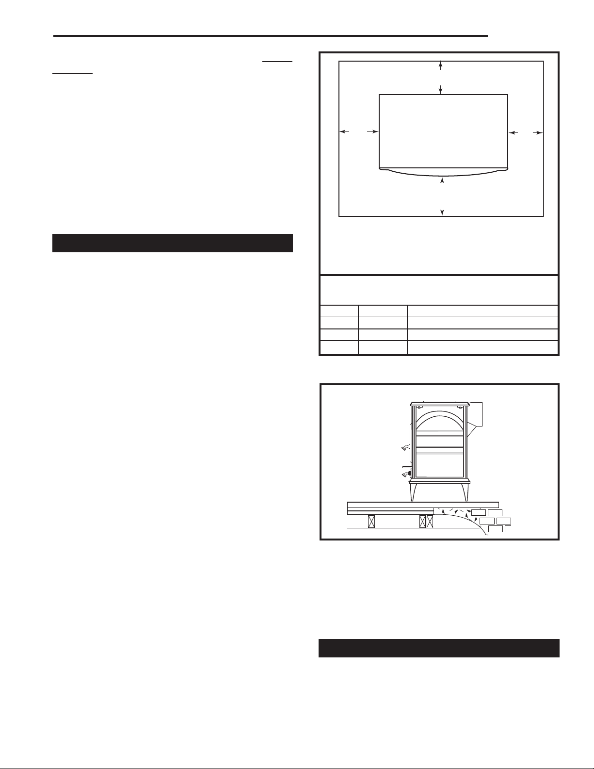
U.S. Installations: The floor protector is required under
the stove and must extend at least 16 inches from the
front and left (loading door) side of the stove, and at
least 6 inches from the right side and rear. (Fig. 12)
Refer to Figure 12 for minimum noncombustible floor
protection dimensions for each stove model.
In Canada: a noncombustible floor protector is required
under the heater also. The floor protector must extend
18 inches (457mm) from the front and left (loading
door) side of the stove, and at least 8 inches (203mm)
from the right side and rear. (Fig. 12)
ST422
Fig. 12 Be sure to follow exactly the floor protection requirements on all four sides of the stove.
Minimum Dimensions for Noncombustible Floor
Protectors (Depth x Width):
Model U.S. Canada
2460 38” x 44” 42” x 48” (1067mm x 1219mm)
2461 38” x 48” 42” x 52” (1067mm x 1320mm)
2462 42” x 52” 46” x 56” (1168mm x 1422mm)
B
B
A
A
U.S. Canada
A. 16” 18” (457 mm)
B. 6” 8” (203 mm)
A
ST423
Fig. 13 Combustible supporting timbers (A) may lie beneath
fireplace hearths; such situations require additional floor
protection.
Due to the side loading door, floor protector requirements call for more protection on the left side than on
the right. If you wish a more balanced look, increase
the other side of the hearth as well. Do not reduce
side protection under any circumstances.
Fireplace Installations
You may install your Dutchwest Convection Heater in
an existing fireplace as a fireplace insert with no legs,*
or with the standard legs attached.

10
Dutchwest
7001135
To install the heater without legs as a fireplace insert,
the floor must be completely noncombustible, such as
an unpainted concrete floor over earth.
Many fireplaces do not satisfy the “completely noncombustible” requirement because the brick or concrete hearth in front of the fireplace opening usually is
supported by heavy wooden framing as in Figure 13.
Because heat passes readily through brick or concrete,
it can easily pass through to the wood. As a result,
such fireplace hearths are considered a combustible
floor. You may not install a heater on a combustible
hearth without legs. Standard leg installations must
include the bottom heat shield. The floor protector
must also meet standard requirements for freestanding
installations.
Floor Protection for Fireplace
Installations with Standard Legs
Fireplace installations with the standard legs and the
bottom heat shield must have a floor protector of the
same construction as that specified for freestanding installations: 1/4” non-asbestos mineral board or equivalent, or 24 gauge sheet metal (that may be covered with
a decorative noncombustible material if you desire).
The floor protector must extend at least 16” (406 mm)
[18” / 457 mm in Canada] from the front of the stove
and from the left (loading door) side, and at least 6”
(152 mm) from the right side and rear. It must also
provide protection beneath any horizontal runs of the
chimney connector, including 2” to either side.
Many raised hearths will extend less than the required
distance from the front of the heater when it is installed.
In such cases, sufficient floor protection, as described
above, must be added to extend the hearth 16” (406
mm) [18” (457 mm) in Canada].
Hearth rugs do not satisfy the requirements for floor
protection.
Fireplace insert installations also have specific clearance requirements to the side walls, side decorative
trim, and fireplace mantel. This information is found in
“Fireplace Installation Clearances” in this section.
REMINDER- FIREPLACE INSERT INSTALLATIONS
WITHOUT LEGS ARE PERMISSIBLE ONLY IF THE
HEARTH IS COMPLETELY NONCOMBUSTIBLE,
SUCH AS UNPAINTED CONCRETE OVER EARTH.
Keep the Stove a Safe Distance
From Surrounding Materials
Both a stove and its chimney connector radiate heat
in all directions when operating. A safe installation requires that adequate clearance be maintained between
the stove and nearby combustible materials to ensure
that such materials do not overheat.
Clearance is the distance between either your stove or
chimney connector, and nearby walls, floors, the ceiling,
and any other fixed combustible surface. Keep furnishings and other combustible materials away from the
stove as well. In general, a distance of 48” (1220 mm)
must be maintained between the stove and moveable
combustible items such as drying clothes, furniture,
newspapers, firewood, etc. Keeping those clearance
areas empty assures that nearby surfaces and objects
will not overheat.
Safe Ways To Reduce Clearances
Your stove has specific clearance requirements that
have been established through careful research and
testing to UL and ULC standards.
Clearance requirements have been established to meet
every installation possibility, and they involve the combination of basic variables:
• When the stove has no listed heat shield
• When the stove has a listed heat shield
• When the wall has no heat shield
• When the wall has a heat shield
• When the stove has a double-wall chimney con-
nector.
• When the stove has a single-wall connector
wit heat shields, or without heat shields.
In general, the greatest clearance is required when you
locate a stove with no heat shield near a wall with no
heat shield. The least clearance is required when both
the stove and the wall have heat shields. Reducing a
stove clearance may require a listed heat shield on the
chimney connector as well, or a double-wall connector.
Clearances may be reduced only by means approved
by the regulatory authority and in accordance with the
clearances listed in this manual. The charts and sample
installations that follow list all the clearances required
for the various installation configurations of Dutchwest
Convection Heaters.
 Loading...