


INSTALLER/CONSUMER SAFETY INFORMATION
PLEASE READ THIS MANUAL BEFORE INSTALLING AND USING APPLIANCE.
WARNING!
IF THE INFORMATION IN THIS MANUAL IS NOT FOLLOWED EXACTLY, AN ELECTRICAL SHOCK OR FIRE MAY RESULT CAUSING PROPERTY DAMAGE, PERSONAL INJURY OR LOSS OF LIFE.
FOR YOUR SAFETY
Service must be performed by a qualified service agency.
DO NOT STORE OR USE GASOLINE OR OTHER FLAMMABLE VAPORS AND LIQUIDS IN THE VICINITY OF THIS OR ANY OTHER APPLIANCE.
Electric Fireplace
Model
DEF33/36;
DEFD33/36
10005696
C US
Homeowner's Installation and
Operating Manual
Vermont Castings, Majestic Products
410 Admiral Blvd. • Mississauga, Ontario, Canada L5T 2N6 • 905-670-7777 www.majesticproducts.com • www.vermontcastings.com
INSTALLER: DO NOT DISCARD THIS MANUAL - LEAVE FOR HOMEOWNER
10005898 9/03 Rev.0

Vermont Castings, Majestic Products, DEF33/36, DEFD33/36
Table of Contents
Please read the Installation & Operating Instructions before using this appliance.
Thank you and congratulations on your purchase of a Vermont Castings, Majestic Products fireplace.
IMPORTANT: Read all instructions and warnings carefully before starting installation. Failure to follow these instructions may result in a possible electric shock, fire hazard and/or injury, and will void the warranty.
Installation Instructions |
|
General Information .................................................................................................... |
3 |
Locating Your Electric Fireplace ................................................................................. |
3 |
Clearance to Combustibles ........................................................................................ |
3 |
Hearth ......................................................................................................................... |
3 |
Cabinet Installations ................................................................................................... |
3 |
Fireplace Dimensions ................................................................................................. |
4 |
Electrical Specifications .............................................................................................. |
4 |
Mantels ....................................................................................................................... |
5 |
Framing and Finishing ................................................................................................ |
6 |
Electrical Connection .................................................................................................. |
6 |
Hard (Direct) Wire Connection ................................................................................... |
6 |
Installation of DEF33 Logs ......................................................................................... |
7 |
Installation of DEF36 Logs ......................................................................................... |
7 |
Service Instructions |
|
Glass Frame Removal ................................................................................................ |
8 |
Glass Information ........................................................................................................ |
8 |
Replacing Light Bulbs ................................................................................................. |
8 |
Cleaning Brass Trim ................................................................................................... |
8 |
Maintenance of Motors ............................................................................................... |
8 |
Electrical Wiring Diagram with Intergral Remote Control ........................................... |
9 |
Electrical Wiring Diagram without Intergral Remote Control .................................... |
10 |
Ceramic Refractory Installation ................................................................................ |
10 |
Operating Instructions |
|
Main ON/OFF Switch ................................................................................................ |
11 |
Heater Control ........................................................................................................... |
11 |
Flame Speed Control ................................................................................................ |
11 |
Re-learn .................................................................................................................... |
11 |
ON/OFF ..................................................................................................................... |
11 |
Replacement Parts |
|
Replacement Parts ................................................................................................... |
12 |
Replacement Parts List ............................................................................................. |
13 |
Options |
|
Bay Window Installation ............................................................................................ |
14 |
Louvre Face Installation ............................................................................................ |
14 |
Louvre Removal ........................................................................................................ |
14 |
Direct (Hard) Wiring .................................................................................................. |
15 |
Warranty ................................................................................................................... |
16 |
2 |
10005898 |

Vermont Castings, Majestic Products, DEF33/36, DEFD33/36
Installation Instructions
General Information
1.Read all instructions before using this appliance.
2.This appliance is hot when in use. To avoid burns, do not let bare skin touch hot surfaces. If provided, use handles when moving this appliance. Keep combustible materials, such as furniture, pillows, bedding, papers, clothes, and curtains at least
3 feet (1 m) from the front of this appliance.
CAUTION: Extreme caution is necessary when any heater is used by or near children or invalids, and whenever the heater is left operating and unattended.
3.If possible, always unplug this appliance when not in use.
4.Do not operate any heater with a damaged cord or plug, or after the appliance malfunctions, or if it has been dropped or damaged in any manner.
5.Any repairs to this fireplace should be carried out by a qualified service person.
6.Under no circumstances should this fireplace be modified. Parts having to be removed for servicing must be replaced prior to operating this fireplace again.
7.Do not use outdoors.
8.This heater is not intended for use in bathrooms, laundry areas and similar indoor locations. Never locate this appliance where it may fall into a bathtub or other water container.
9.Do not run cord under carpeting. Do not cover cord with throw rugs, runners or the like. Arrange cord away from traffic areas and where it will not be tripped over.
10.To disconnect this appliance, turn controls to the off position, then remove plug from outlet.
11.Connect to properly grounded outlets only.
12.This appliance, when installed, must be electrically grounded in accordance with local codes; or, in the absence of local codes, with the current CSA C22.1 Canadian Electrical Code; or, for U.S.A. installations, follow local codes and the National Electrical Code, ANSI/NFPA NO. 70.
13.Do not insert or allow foreign objects to enter any ventilation or exhaust opening, as this may cause an electric shock or fire, or damage the appliance.
14.To prevent a possible fire, do not block air intakes or exhaust in any manner. Do not use on soft surfaces, like a bed, where openings may become blocked.
15.This appliance has hot and arcing or sparking parts inside. Do not use it in areas where gasoline, paint or flammable liquids are used or stored. This fireplace should not be used as a drying rack for clothing, nor should Christmas stockings or decorations be hung in the area of it.
16.Use this appliance only as described in this manual. Any other use not recommended by the manufacturer may cause fire, electric shock or injury to persons.
17.Avoid the use of an extension cord because the extension cord may overheat and cause a risk of fire. However, if you have to use an extension cord, the cord shall be No. 14 AWG minimum size and rated not less than 1875 Watts. The extension cord must be a three wire cord with grounding type plug and cord connection. The extension cord shall not be more than 20 feet in length.
18.SAVE THESE INSTRUCTIONS.
Locating Your Electric Fireplace
Your new fireplace may be installed into an existing masonry or zero clearance fireplace. It may also be installed using a prefabricated cabinet available from your dealer or be built into a wall.
When choosing a location for your new fireplace, ensure that the general instructions are followed. For best effect install the fireplace out of direct sunlight.
Clearance to Combustibles
Sides .............................. |
0 mm |
0 inches |
Floor ............................... |
0 mm |
0 inches |
Top ................................. |
0 mm |
0 inches |
Hearth
A hearth is not mandatory; however, for aesthetic purposes, it is recommended you use a noncombustible hearth which does not obstruct louvre opening.
Cold climate installation recommendation: When installing this unit against a noninsulated exterior wall or chase, it is mandatory that the outer walls be insulated to conform to applicable insulation codes.
Cabinet Installations
Cabinets are available from your dealer which allow for fast, convenient installation of your fireplace against existing walls.
10005898 |
3 |

Vermont Castings, Majestic Products, DEF33/36, DEFD33/36
Fireplace Dimensions
|
|
Rough |
H |
|
|
|
Opening |
|
|
|
|
|
|
|
|
M |
Depth |
|
|
|
|
|
|
|
|
|
L |
|
|
|
|
G |
|
|
M |
O |
K - Rough Opening Width |
||
|
|
|
|
|
|
|
Rough |
|
|
|
N |
Opening |
|
|
|
|
Height |
|
|
|
|
|
|
F |
|
B |
J |
C |
D |
|
|
|||
|
|
|
|
E |
|
|
|
A |
I |
|
|
|
|
|
Fig. 1 Fireplace specifications and framing dimensions |
|
|
||
|
Ref. |
DEF33 |
|
DEF36 |
|
A |
33" (838 mm) |
|
36" (914 mm) |
|
B |
28 7/8" (733 mm) |
|
34 1/4" (870 mm) |
|
C |
31" (787 mm) |
|
33" (838 mm) |
|
D |
16 3/8" (416 mm) |
|
21" (533 mm) |
|
E |
6 27/64" (163 mm) |
|
6 27/64" (163 mm) |
|
F |
4" (102 mm) |
|
5 3/8" (137 mm) |
|
G |
11 1/2" (292 mm) |
|
14" (356 mm) |
|
H |
22 1/16" (560 mm) |
|
22 1/8" (562 mm) |
|
I |
3" (76 mm) |
|
3 3/4" (95 mm) |
|
|
Framing Dimensions |
|
|
|
J |
29 5/8" (752 mm) |
|
34 1/2" (876 mm) |
|
K |
33 1/2" (851 mm) |
|
36 1/2" (927 mm) |
|
L |
12" (305 mm) |
|
14 1/2" (362 mm) |
|
M |
36" (914 mm) |
|
36" (914 mm) |
|
N |
51" 1295 mm) |
|
51" 1295 mm) |
|
O |
25 1/2" (648 mm) |
|
25 1/2" (648 mm) |
Electrical Specifications
Voltage: 120VAC, 60Hz
Total Amps: 12.5 Amps
Total Watts: 1500 Watts
Heater Rating: 1300 Watts
4 |
10005898 |
Vermont Castings, Majestic Products, DEF33/36, DEFD33/36
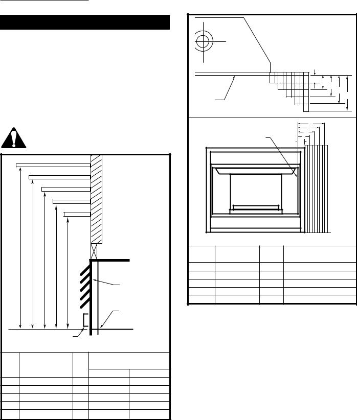
Mantels
The height that a combustible mantel is fitted above the fireplace is dependent on the depth of the mantel. This also applies to the distance between the mantel leg (if fitted) and the fireplace.
For the correct mounting height and widths, refer to Figures 2a, 2b and the Mantel Chart below.
The distances and reference points are not affected by the fitting of a bay window front trim kit.
Noncombustible mantels and legs may be installed at any height and width around the appliance.
When using paint or lacquer to finish the mantel, such paint or lacquer must be heat resistant to prevent discoloration.
|
|
|
|
V |
|
|
|
|
|
|
W |
|
|
|
|
|
|
X |
|
|
|
|
|
|
Y |
|
|
|
|
|
|
Z |
|
|
A |
B |
C |
D |
E |
|
|
|
|
|
|
|
Fireplace |
|
|
|
|
|
|
Top Louvre |
|
|
|
|
|
|
Opening |
|
|
|
|
|
|
Top of Combus- |
|
|
|
|
|
|
tion Chamber |
|
Bottom of Door Trim |
|
CFM146 |
||||
|
|
|
Mantel Chart |
|
||
|
Mantel Shelf |
Mantel from Top |
||||
Ref. or Breast Plate Ref. |
of Comb. Chamber |
|||||
|
Depth |
|
|
DEF33 |
DEF36 |
|
V |
10” (254 mm) |
A |
17" (432 mm) |
19" (483 mm) |
||
W |
8” (203 mm) |
B |
15" (381 mm) |
17" (432 mm) |
||
X |
6” (152 mm) |
C |
13" (330 mm) |
15" (381 mm) |
||
Y |
4” (101 mm) |
D |
11" (279 mm) |
13" (330 mm) |
||
Z |
2” (50 mm) |
E |
9" (229 mm) |
11" (279 mm) |
||
Fig. 2a Combustible mantel minimum installation
|
|
|
J |
I H |
Black |
|
|
|
|
|
|
|
G |
|
Surround |
|
|
F |
|
Face |
|
|
|
|
Mantel |
|
|
||
|
|
|
||
CFM164a |
Leg |
|
|
|
|
Side of |
|
K |
|
|
|
L |
|
|
|
Combustion |
M |
|
|
|
Chamber |
|
N |
|
|
|
|
O |
|
|
|
|
|
CFM170 |
|
Mantel |
|
Mantel Leg from Side |
|
Ref. |
Leg Depth |
Ref. |
of Comb. Opening |
|
F |
10” (254mm) |
K |
11Z\x” (292mm) |
|
G |
8” (203mm) |
L |
9Z\x” (241mm) |
|
H |
6” (152mm) |
M |
7Z\x” (191mm) |
|
I |
4” (101mm) |
N |
5Z\x” (140mm) |
|
J |
2” (50mm) |
O |
3Z\x’” (89mm) |
|
Fig. 2b Combustible mantel leg minimum installation |
||||
10005898 |
5 |
 Loading...