


Vermont Castings Madison
The Madison
Woodburning Stove
Models
1655, 1656, 1657, 1658, 1659
Homeowner’s
Installation and
Operating
Manual
For use in the
United States and Canada
SAFETY NOTICE: IF THIS APPLIANCE IS NOT PROPERLY INSTALLED, OPERATED AND MAINTAINED, A HOUSE FIRE MAY RESULT.
TO REDUCE THE RISK OF FIRE, FOLLOW THE INSTALLATION INSTRUCTIONS. FAILURE TO FOLLOW INSTRUCTIONS MAY RESULT IN PROPERTY DAMAGE, BODILY INJURY OR EVEN DEATH. CONTACT LOCAL BUILDING OFFICIALS ABOUT RESTRICTIONS AND INSTALLATION INSPECTION REQUIREMENTS IN YOUR AREA.
Do Not Discard This Manual: Retain for Future Use
30001453 10/02 Rev. 1
1
Vermont Castings Madison
Introduction
Thank you for choosing a Vermont Castings Madison to meet your heating needs.
We're confident you will find the Madison to be an effective woodburning heater incorporating modern, non-catalytic combustion technology with the classic aesthetic appeal of its Vermont Castings lineage.
The Madison achieves high-efficiency through precisely calibrated delivery of primary and secondary air into a refractory-insulated firebox. Properly operated and maintained according to the guidelines in this manual, your Madison will provide safe, dependable, and economical heating for years to come.
The Madison Model 1655 Series has been tested and is listed by Canadian Standards Association (CSA). The test standards are ANSI/UL-1482 for the United States and ULC S627 and CAN/CSA B366.2 for Canada.
The Madison Model 1655 |
Series is listed for burning wood fuel only. Do not burn other fuels. |
C |
US |
|
|
||
The Madison Model 1655 |
Series is approved for installation in manufactured (mobile) homes |
|
|
in the Unties States only, using the optional Mobile Home Kit #1894 in accordance with the |
|
|
|
instructions in that kit an any local codes. |
|
|
|
The Madison Model 1655 Series complies with the standards set forth by the Federal Environmental Protection Agency, 40 CFR Part 60.532(b)(2), as stated on the permanent label attached to each stove. The Madison Model 1655 Series meets Washington State requirements.
We recommend that you hire a professional, solid-fuel stove technician to install your Madison, or to advise you on the installation should you attempt to install it yourself. Consult the authority having local jurisdiction (such as a municipal building department, fire department, fire prevention bureau, etc.) before installation to determine the need for a building permit. Also, consult your insurance agent to be sure your installation complies with specific requirements that may vary locally.
In addition to directions on installation and operation, this manual includes directions on maintenance and assembly. Please read this entire manual before you install or operate your new room heater.
Save These Instructions For Future Reference.
Table of Contents
Specifications ..................................... |
3 |
Installation Requirements .................. |
4 |
Clearances ......................................... |
12 |
Assembly ........................................... |
15 |
Operation ........................................... |
17 |
Maintenance ...................................... |
20 |
Draft Management ............................. |
22 |
Parts List ............................................ |
25 |
Installation
Accessories
#1891 Outside Air Kit
#1892 Bottom Heat Shield Kit
#1893 Rear Heat Shield Kit
#1894 Mobile Home Kit
Proposition 65 Warning: Fuels used in gas, woodburning or oil fired appliances, and the products of combustion of such fuels, contain chemicals known to the State of California to cause cancer, birth defects and other reproductive harm.
California Health & Safety Code Sec. 25249.6
2
Vermont Castings Madison
Specifications
Madison, Model 1655 Series
Maximum heat output |
......................... 39,700 Btu’s/hr.1 |
Area heated...................................... |
Up to 1600 sq. ft.2 |
Fuel size/type ...................................... |
18” (46 cm) logs |
Loading ..................................................... |
Front & Side |
Chimney connector .................... |
6” (150 mm) diameter |
Chimney flue size ...................... |
6” (150 mm) minimum |
Flue exit position ........................................ |
Top or Rear |
Primary air ... Manually set, thermostatically maintained
Ash handling system ..................... |
|
Removable ash pan |
Glass panel ........................ |
High-temperature Infra-red |
|
Weight ............................................................... |
|
420lbs. |
Width (Left leg - Right leg) ...................... |
|
29” (59.0 cm) |
Depth (Front Plate - Flue Collar) |
............. 25” (64.0 cm) |
|
Height ...................................................... |
|
28” (79.5 cm) |
1This value can vary depending on how the stove is operated, the type and moisture content of the fuel used, as well as the design, construction and climatic location of your home. Figures shown are based on maximum fuel consumption obtained under laboratory conditions and on average efficiencies.
2These values are based on operation in building codeconforming homes under typical winter climate conditions in New England. If your home is of nonstandard construction (e.g., unusually well insulated, not insulated, built under ground, etc.) or if you live in a more severe or more temperate climate, these figures may not apply. Since so many variables affect performance, consult your Vermont Castings Majestic Products Company authorized dealer to determine realistic expectations for your home.
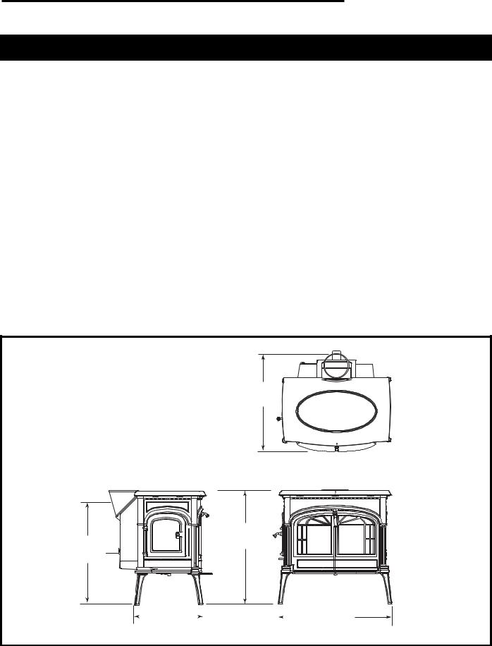
Drawings not to scale.
25"
(635mm)
28”
24³⁄” (710mm) (630mm)
|
18” |
|
|
|
|
|
29” |
(470mm) |
|
|
|
(740mm) |
|||
|
|
|
|
|
|
|
|
1128
Fig. 1 Madison 1655 dimensions.
3
Vermont Castings Madison
Installation
SAFETY NOTICE: If your stove is not properly installed, operated and maintained, a house fire may result. For safety, follow all installation, operation and maintenance directions. Contact local building officials about restrictions and installation inspection requirements in your area.
Before you begin an installation, review your plans to be certain that:
•Your stove and chimney connector will be far enough from combustible material to meet all clearance requirements.
•The floor protector is large enough and is constructed properly to meet all requirements.
•You have all necessary permits from local authorities.
Your local building official is the final authority for approving your installation as safe and determining that it meets local and state codes.
The metal label permanently attached to the back of the stove indicates that the Madison has been tested to current UL and ULC standards by CSA. Clearance and installation information is also printed on the label. Local authorities generally will accept the label as evidence that, when the stove is installed according to the information on the label and in this manual, the installation meets codes and can be approved. Codes, however, vary in different areas. Before starting the installation, review your plans with the local building authority. Your local dealer can provide any additional information needed.
For any unresolved questions about installation, refer to the National Fire Protection Association’s publication ANSI/NFPA 211–1988 Standard for Chimneys, Fireplaces, Vents and Solid Fuel Burning Appliances. In Canada, the equivalent publication is CSA CAN-B365, Installation Code for Solid Fuel Burning Appliances and Equipment. These standards are the bases for many national codes. They are nationally recognized and are accepted by most local authorities. Your local dealer or your local building official may have a copy of these regulations.
IMPORTANT: FAILURE TO FOLLOW THESE INSTALLATION INSTRUCTIONS MAY RESULT IN A DANGEROUS SITUATION, INCLUDING A CHIMNEY OR HOUSE FIRE. FOLLOW ALL INSTRUCTIONS EXACTLY AND DO NOT ALLOW MAKESHIFT COMPROMISES TO ENDANGER PROPERTY AND PERSONAL SAFETY.
Chimneys
Your stove must be connected either to a sound masonry chimney that meets local codes, to a relined masonry chimney that meets local codes, or to an approved prefabricated metal chimney. Whichever of those types you use, the chimney and chimney connector must be in good condition and kept clean.
If you use an existing masonry chimney, it must be inspected to ensure safe condition before the stove is installed. Your local professional chimney sweep, building inspector, or fire department official will be able to make the inspection or direct you to someone who can.
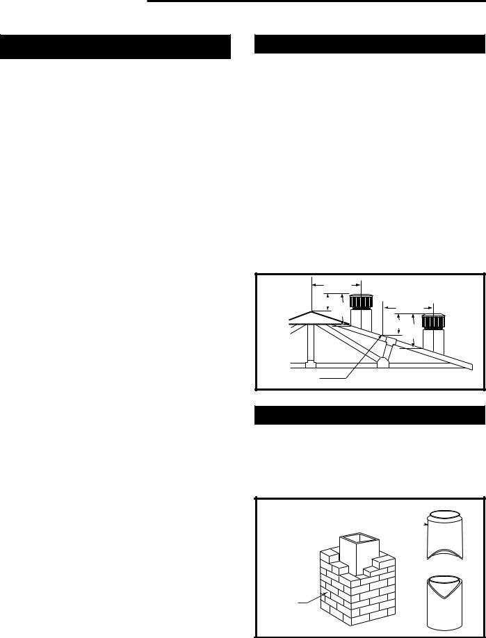
The chimney should extend at least 3' (900 mm) above the highest point where it passes through a roof, and at least 2' (600 mm) higher than any portion of a building within 10' (3 m).
To assure proper draft and good performance, any chimney used with this stove should extend at least 16' (5 m) above the flue collar of the stove.
0 TO 10' |
|
2' Min. |
|
3' |
0 TO 10' |
Min. |
|
|
2' Min.3' |
|
Min. |
Reference Point |
AC617 |
|
|
Fig. 2 The 2'-3'-10' Chimney Rule. |
|
Masonry Chimneys
An existing masonry chimney must be inspected to confirm that it has a lining. Do not use an unlined chimney. The chimney also should be examined for cracks, loose mortar, other signs of deterioration, and blockage. Repair any defects before the chimney is used with your stove.
A prefabricated doublewall insulated chimney 

A tile-lined masonry chimney
ST241
Fig. 3 Standard Chimney Types
4
Masonry Chimneys, cont'd.
•Unused openings in an existing masonry chimney must be sealed with masonry to the thickness of the chimney wall, and the chimney liner should be repaired. Openings sealed with pie plates or wallpaper are a hazard and should be sealed with mortar or refractory cement. In the event of a chimney fire, flames and smoke may be forced out of these unused thimbles.
•The chimney should be thoroughly cleaned before use.
•A newly-built masonry chimney must conform to the standards of local building code, or, in the absence of a local code, to a recognized national code.
Masonry chimneys must be lined, either with codeapproved masonry or precast refractory tiles, stainless steel pipe, or a code-approved, "poured-in- place" liner. The chimney clean-out door must seal tightly to ensure a good draft.
Prefabricated Chimneys
A prefabricated metal chimney must be one that is tested and listed for use with solid-fuel burning appliances to the High-Temperature (H.T.) Chimney Standard UL-103-1985 (2100° F.) for the United States, and High Temperature (650°C) Standard ULC S-629 for Canada.
Chimney Size
This Madison is approved for venting into a masonry chimney with a nominal flue size of 8" x 8" (200 x 200 mm), and into a round flue size of 8" (200 mm) or 6" (150 mm). It may be vented into larger chimneys as well, however, chimneys with liners larger than 8" x 12" (200 x 300 mm) may experience rapid cooling of smoke and reduction in draft, especially if they are located outside the home. Such large chimneys may need to be insulated or relined for proper stove performance.
DO NOT CONNECT THIS UNIT TO A CHIMNEY FLUE SERVING ANOTHER APPLIANCE.
NOTE: DO NOT VENT THIS STOVE INTO A FACTORY-BUILT (ZERO-CLEARANCE) FIREPLACE. THIS STOVE HAS NOT BEEN TESTED AND LISTED FOR THAT TYPE OF INSTALLATION. FACTORY-BUILT FIREPLACES AND THEIR CHIMNEYS ARE SPECIFICALLY DESIGNED AS A UNIT FOR USE AS FIREPLACES. IT MAY VOID THE LISTING OR BE HAZARDOUS TO ADAPT THEM FOR ANY OTHER USE.
DO NOT CONNECT THE STOVE TO ANY AIR DISTRIBUTION DUCT OR SYSTEM.
Vermont Castings Madison
Chimney Connector Guidelines
A chimney connector is the double-wall or singlewall pipe that connects the stove to the chimney. The chimney itself is a masonry or prefabricated structure that encloses the flue. Chimney connectors are used only to make the connection from the stove to the chimney. They are for interior use only.
Double-wall connectors must be tested and listed for use with solid-fuel burning appliances. Single-wall connectors should be made of 24 gauge or heavier steel, and should be 6" (150 mm) in diameter. Do not use galvanized chimney connector; it cannot withstand the high temperatures that can be reached by smoke and exhaust gases, and may release toxic fumes under high heat.
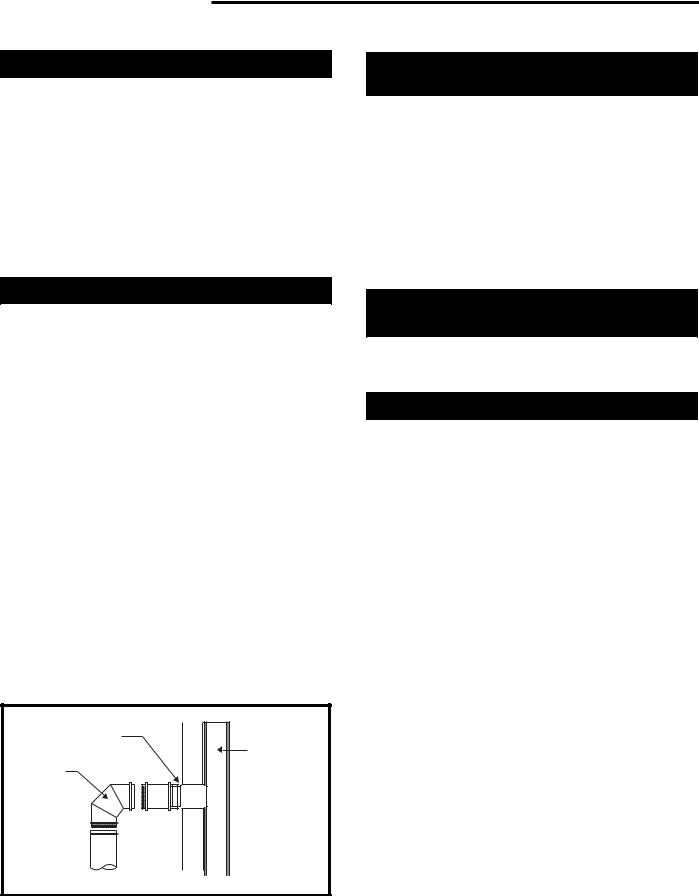
If possible, do not pass the chimney connector
through a combustible |
|
|
|
|
|
|
|
|
|
|
|
|
|
|
|
|
wall or ceiling. If |
|
|
|
|
|
|
|
|
|
|
|
|
|
|
|
|
|
|
|
|
|
|
|
|
|
|
|
|
|
|
|
||
passage through a |
Toward |
|||||||||||||||
combustible wall is |
||||||||||||||||
stove |
|
|
|
|
|
|
|
|
|
|
|
|
|
|
||
unavoidable, refer to |
|
|
|
|
|
|
|
|
|
|
|
|
|
|
||
|
|
|
|
|
|
|
|
|
|
|
|
|
|
|
||
the recommendations |
|
|
|
|
|
|
|
|
|
|
|
|
|
|
|
|
in the section following |
|
|
|
|
|
|
|
|
|
|
|
|
|
|
|
|
|
|
|
|
|
|
|
|
|
|
|
|
|
|
|
||
on Wall Pass- |
|
|
|
|
|
|
|
|
|
|
|
|
|
|
|
|
throughs. Do not pass |
|
|
|
|
|
|
|
|
|
|
|
|
|
|
|
|
the connector through |
|
|
|
|
|
|
|
|
|
|
|
|
|
|
Flue gas |
|
an attic, a closet or |
|
|
|
|
|
|
|
|
|
|
|
|
|
|
direction |
|
|
|
|
|
|
|
|
|
|
|
|
|
|
|
|
||
any similar concealed |
|
|
|
|
|
|
|
|
|
|
|
|
|
|
|
|
space. The whole |
|
|
|
|
|
|
|
|
|
|
|
|
|
|
ST242 |
|
chimney connector |
|
|
|
|
|
|
|
|
|
|
|
|
|
|
|
|
Fig. 4 |
Chimney connector. |
|||||||||||||||
should be exposed and |
||||||||||||||||
|
|
|
|
|
|
|
|
|
|
|
|
|
|
|
||
accessible for inspection and cleaning. |
||||||||||||||||
Install the single wall chimney connector not less |
||||||||||||||||
than 23" (585 mm) from the ceiling. Keep it as short and direct as possible, with no more than two 90 degree turns. If possible, use 45 degree elbows. Slope horizontal runs of connectors upward 1/4" per foot (20 mm per meter) going from the stove toward the chimney. The recommended maximum length of a horizontal run is 3 feet (1 meter), and the total length of chimney connector should be no longer than 8 feet (2.5 meters).
In cathedral ceiling installations, extend the prefabricated chimney downward to within 8 feet (2.5 meters) of the stove.
SAFETY NOTE: ALWAYS WEAR GLOVES AND PROTECTIVE EYEWEAR WHEN DRILLING, CUTTING OR JOINING CHIMNEY CONNECTOR SECTIONS .
5
Vermont Castings Madison
Double-wall Chimney Connectors
The Madison is approved for installation in the U.S. and Canada with double-wall chimney connectors that have been tested and listed for use with solid-fuel burning appliances by a recognized testing laboratory.
Follow the instructions for assembling and installing double-wall connectors provided by the manufacturer of the double-wall chimney. To ease assembly and help assure safety, use chimney components manufactured by a single source.
NOTE: For installations using double-wall connectors, minimum clearances must conform to those listed in the clearance chart on Page 12.
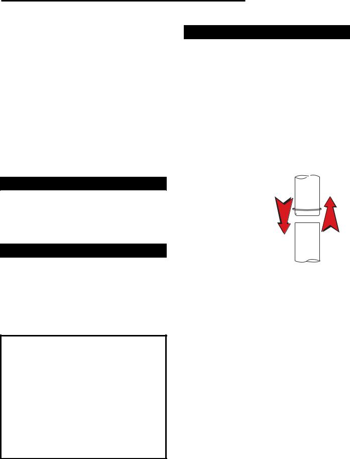
Single-wall Chimney Connectors
•Beginning at the flue collar of the stove, assemble the chimney connector. Insert the first crimped end into the stove’s flue collar, and keep each crimped end pointing toward the stove. Using the holes in the flue collar as guides, drill 1/8" (3 mm) holes in the bottom of the first section of chimney connector and secure it to the flue collar with three #10 x 1/2" sheet metal screws.
•Secure each joint between sections of chimney connector, including telescoping joints, with at least three sheet metal screws. The predrilled holes in the top of each section of chimney connector serve as guides when you drill 1/8" (3 mm) holes in the bottom of the next section.
•Secure the chimney connector to the chimney. Instructions for various installations follow.
•Be sure the installed stove and chimney connector are correct distances from nearby combustible material.
Note: Special slip pipes and thimble sleeves that form telescoping joints between sections of chimney connector are available to simplify assembly. Slip pipes eliminate the need to cut individual connector sections. Consult your local dealer about these special connector sections.
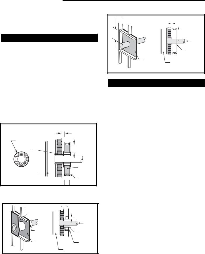
Thimble Sleeve
Flue
Chimney
Connector
 Keep sleeve
end flush with flue tile
ST243
Fig. 5 The thimble, made of either ceramic or metal, must be cemented securely in place.
Securing the Single-wall Connector to a Prefabricated Chimney
Follow the installation instructions of the chimney manufacturer exactly.
Special adaptors are available from your local dealer to make the connection between the prefabricated chimney and the chimney connector. The top of such adaptors attach directly to the chimney or to the chimney’s ceiling support package. The bottom of the adaptor is secured to the chimney connector.
The adaptor forms a union between the chimney and chimney connector that ensures any soot or creosote falling from the inner walls of the chimney will stay inside the chimney connector.
Securing the Single-wall Connector to a Masonry Chimney
The Madison may be connected to either a freestanding masonry chimney or to a fireplace masonry chimney.
Freestanding Installations
If the chimney connector must pass through a combustible wall to reach the chimney, follow the recommendations for Wall Pass-Through construction on pages 7-8.
The opening through the chimney wall to the flue - the "breech" – must be lined with a ceramic or metal thimble which is securely cemented in place. (Fig. 5)
A metal pipe section called the “thimble sleeve,” slightly smaller in diameter than standard connector and the thimbles, will allow the removal of the chimney connector system for inspection and cleaning. Thimble sleeves are available from your local dealer.
To install a thimble sleeve, slide it into the breech until it is flush with the inner flue wall. Be sure that it does not extend into the flue passage where it could interfere with the draft.
The thimble sleeve should protrude 1-2" (25-50 mm) into the room. Use furnace cement and thin gasketing to seal the sleeve in place in the thimble. Secure the chimney connector to the outer end of the sleeve with sheet metal screws.
6

Connection Above the Fireplace
In this installation, the chimney connector enters the fireplace flue through a thimble located above the fireplace. (Fig. 6) The liner of the fireplace chimney should extend at least to the point at which the chimney connector enters the chimney. Follow all the guidelines for installing a chimney connector into a freestanding masonry chimney, and pay special attention to these additional points:
•The stove and chimney connector clearances to combustible mantel and trim materials are the same as clearances to combustible walls. If necessary, use a combination of mantel, trim, and connector heat shields to provide the required clearances. Refer to page 12.
•Double-check connector clearance to the ceiling.
•The fireplace damper must be closed and sealed to prevent room air from being drawn up the flue which could reduce performance. However, it must be possible to reopen the damper to inspect or clean the chimney.
•Floor protection requirements also apply to fireplace installations.
Wall Pass-throughs
Whenever possible, design the installation so that the connector does not pass through a combustible wall. If you must include a wall pass-through in your installation, check with your building inspector before you begin. Also check with the chimney connector manufacturer for any specific requirements.
Consult with your dealer regarding special connection components available for use as wall passthroughs. Use only parts that have been tested and listed for use as a wall pass-through.
U.S. Requirements:
The National Fire Protection Association (NFPA) has established guidelines for use in the United States for passing chimney connectors through combustible walls. Many building code inspectors follow these guidelines.
Figure 7 shows one NFPA-approved method. All combustible material in the wall is cut away to provide 12" (300 mm) clearance to the connector. Brick and mortar are used to enclose the clearance area.
Alternate methods approved by the NFPA:
•Using a section of double-wall chimney with a 9" (230 mm) clearance to combustibles. (Fig. 8)
•Placing a chimney connector pipe inside a steel double-wall ventilated thimble, which is then separated from combustibles by 6" (150 mm) of fiberglass insulating material. (Fig. 9)
Vermont Castings Madison
Chimney Connector
Heat Shield |
* |
|
|
Note clearance |
|
*requirement on |
* |
pages 12-13 |
|
|
|
|
Mantel |
ST244a
Fig. 6 If the clearance between the chimney connector and either the ceiling or the mantel is inadequate, a protective heat shield is required.
Fire clay liner
A |
A |
Min. 2" (51mm) Chimney clearance to brick and combustibles 


Masonry |
|
Min. 12" |
Chimney |
Flue |
(305 mm) |
constructed |
|
|
|
|
|
to NFPA |
Chimney |
Chimney |
211 |
|
|
|
connector |
|
|
|
|
|
|
Fire clay |
|
|
liner |
A = Minimum 12" (305 mm) brick construction between liner and
combustible framing materials
ST272
Fig. 7 Masonry Wall Pass-through with single wall chimney connector.
|
Solid |
|
Min. 2" |
|
insulated, |
|
|
|
listed factory- |
|
(51mm) |
|
built chimney |
|
|
Min. 9" |
length set flush |
|
|
with flue |
|
Min. 9" |
|
230mm |
|
|
(230mm) |
|
|
Flue |
|
|
Masonry |
Chimney |
|
|
Chimney |
|
|
|
Chimney |
Connector |
|
|
constructed to |
||
|
Air Space |
||
|
|
||
|
NFPA 211 |
|
|
|
|
|
|
|
Non-soluble |
24 ga.Sheet |
|
Sheet Steel |
Steel |
|
|
refractory cement |
Supports |
|
|
Supports |
||
ST273 |
|
|
|
|
|
|
Fig. 8 Wall Pass-through using factory-built insulated chimney section.
7
Vermont Castings Madison
•Placing a chimney connector pipe inside a section of 9" (230 mm) diameter, solid-insulated, factorybuilt chimney, with two inches of air space between the chimney section and combustibles. (Fig. 10)
Canadian Requirements:
In Canada, the Canadian Standards Association has established specific guidelines regarding wall passthough design. Figure 11 shows one approved method in which all combustible material in the wall is cut away to provide the required 18" (460 mm) clearance around the connector. The resulting space must remain empty. A flush-mounted sheet metal cover may be used on one side only. If covers must be used on both sides, each cover must be mounted on noncombustible spacers at least 1" (25 mm) clear of the wall.
Your local dealer or your local building inspector can provide details of other approved methods of passing a chimney connector through a combustible wall.
In Canada, this type of installation must conform to CAN/CSA-B365, Installation Code for Solid Fuel Burning Appliances and Equipment.
Chimney clearance to sheet |
|
|
steel supports and combustibles |
2" (51mm) Min. |
|
Steel Thimble |
|
|
with two 1" |
|
|
(25mm) Ventilated |
|
Min. 6" |
Channels |
|
(152mm) |
|
|
|
|
Flue |
Chimney Connector |
|
Chimney |
Glass Fiber |
Masonry Chimney |
|
Insulation |
constructed to NFPA 211 |
|
|
|
|
24 ga.Sheet |
|
|
Steel Supports |
ST274
Fig. 9 Wall Pass-through using single wall chimney connector with a ventilated steel thimble.
Chimney clearance to sheet steel |
|
|
|
|
|
|
2" (51mm) |
||||
|
|
|
|
|
|
||||||
supports and combustibles |
|
|
|
|
|
|
|
|
|
|
Min. |
|
|
|
|
|
|
|
|
|
|||
|
|
|
|
|
|
|
|
|
|
|
|
2" (51mm) Min. |
Flue |
|
|
air space |
2" (51mm) Min. |
||
|
|||
|
Chimney |
||
|
Chimney |
||
|
|
||
|
|
Connector |
|
Prefab |
|
Prefab |
|
Chimney |
|
||
|
Chimney |
||
Section |
|
||
|
Section |
||
|
|
||
24 ga. Sheet |
|
24 ga. Sheet |
|
Steel Supports |
|
Steel Supports |
ST275 |
Masonry Chimney |
constructed to NFPA 211 |
Fig. 10 Wall Pass-through with ventilated steel thimble.
Min. 18" |
|
|
|
|
|
|
|
|
|
|
|
(460mm) |
Chimney clearance to sheet steel |
|
|
2" (51mm) |
|||||||
|
|
||||||||||
|
supports and combustibles |
|
|
|
|
|
|
|
|
Min. |
|
|
|
|
|
|
|
||||||
|
|
|
|
|
|
|
|
|
|
|
|
24 ga. Sheet Steel Support (one side only)
ST276
Flue |
Min. 18" |
(460mm) |
|
Chimney |
Chimney |
|
|
|
Connector |
|
24 ga.Sheet |
|
Steel Support |
|
Masonry Chimney |
|
constructed to CAN/CSA- |
|
B365 |
Fig. 11 CSA approved Wall Pass-through.
Floor Protection
A tremendous amount of heat radiates from the bottom plate of your Madison. The floor area directly under and around the stove will require protection from radiant heat as well as from stray sparks or embers that may escape the firebox.
Heat protection is provided through the use of a Vermont Castings Bottom Heat Shield #1892. Spark and ember protection must be provided by a floor protector constructed with noncombustible material as specified.
Most installations will require that the bottom heat shield be attached. Only when the stove is placed on a completely noncombustible surface such as unpainted concrete over earth may it be used without the heat shield.
Even when the bottom heat shield is installed, you must provide special protection to the floor beneath. For installations with the heat shield attached, use a noncombustible floor protector such as 1/4” nonasbestos mineral board or equivalent, or 24 gauge sheet metal. The floor protector may be covered with a noncombustible decorative material if desired. Do not obstruct the space under the heater.
Protection requirements vary somewhat between the United States and Canada as follows:
For U.S. installations the floor protector is required under the stove and must extend at least 18” from the front of the stove (“D”, Fig. 12), at least 4” from the right side and rear (“C”, Fig. 12) and 16” from the left side (“E”, Fig. 12). It must also extend under the chimney connector and 2” to either side (“F”, Fig. 12).
To meet these requirements, a floor protector must be at least 48” wide (“A”,Fig. 12) and 48” deep (“B”,Fig. 12)
In Canada, a noncombustible floor protector is required under the heater also. The floor protector must extend 18” (460 mm) to the front (D), and 8” (203 mm) from the right side (C) and rear (C) and 18” (460mm) from left side (E).
8
To meet these requirements, a floor protector must be at least 54” (1372mm) wide (“A”,Fig. 12) and 52” (1320mm) deep (“B”, Fig. 12).
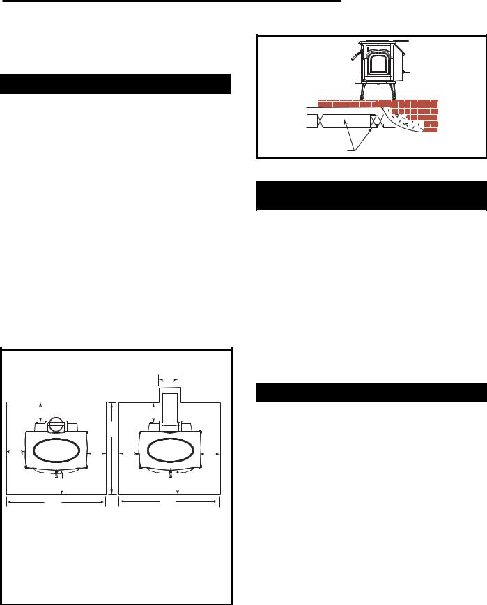
Fireplace Hearth Protection
Do not assume that your fireplace hearth is completely noncombustible. Many fireplace hearths do not satisfy the “completely noncombustible” requirement because the brick or concrete in front of the fireplace opening is supported by heavy wood framing. (Fig. 13) Because heat is readily conducted by brick or concrete, it can easily pass through to the wood. As a result, such fireplace hearths can be a fire hazard and are considered a combustible floor.
For all fireplace installations, follow the floor protection guidelines described above.
Keep in mind that many raised hearths will extend less than the required clearance from the front of the heater when it is installed. In such cases, sufficient floor protection as described above must be added in front of the hearth to satisfy the minimum floor protector requirement from the front of the stove: 18" (460 mm) from the front in the United States and 18" (460 mm) from the front in Canada.
Hearth rugs do not satisfy the requirements for floor protection as they are only fire-retardant, not fire proof.
Floor Protection Requirements |
|
|||
|
|
|
Rear Vent |
|
|
|
|
F |
|
Top Vent |
|
|
|
|
C |
|
|
C |
|
|
|
B |
|
|
E |
C |
|
E |
C |
|
|
|||
D |
|
|
D |
|
A |
|
|
A |
|
|
U. S. |
Canada |
|
|
A: |
48” |
54” |
(1372mm) |
|
B: |
48” |
52” |
(1321mm) |
|
C: |
4” |
8” |
(203mm) |
|
D: |
18” |
18” |
(460mm) |
|
E: |
16” |
18” |
(460mm) |
|
F: |
10” |
10” |
(254mm) |
ST500a |
Fig. 12 These dimensions are minimum requirements only. Use greater dimensions whenever possible.
Vermont Castings Madison
Wood framing |
|
requires protection |
ST247a |
from radiant heat |
Fig. 13 Supporting timbers under fireplace hearths are considered to be combustible.
Clearance to Surrounding
Combustible Materials
When the stove is operating, both the stoveplate and the chimney connector radiate heat in all directions. A safe installation requires that adequate clearance be maintained between the stove and nearby combustible materials to ensure that those materials do not overheat.
Clearance is the distance between either your stove or chimney connector, and nearby walls, floors, the ceiling, and any other fixed combustible surface.
Keep furnishings and other combustible materials away from the stove as well. In general, a distance of 48" (1220 mm) must be maintained between the stove and moveable combustible items such as drying clothes, furniture, newspapers, firewood, etc. Keep this area empty of any combustible material.
Safe Ways To Reduce Clearances
The Madison clearance requirements, listed and diagramed on pages 12-13, have been established through testing to UL and ULC standards to meet most installation configurations. These involve four basic variables:
•When neither the chimney connector nor the wall has a heat shield installed.
•When only the chimney connector has a heat shield installed.
•When only the wall has a heat shield mounted on it.
•When a heat shield is installed on both the chimney connector and wall.
In general, the greatest clearance is required when the stove will be positioned with no heat shield near a wall with no heat shield. The least clearance is required when both the stove and the wall have heat shields. Reducing a stove clearance may require installation of a listed heat shield on the chimney connector as well.
Clearances may be reduced only by means approved by the regulatory authority, or in accordance with the clearances listed in this manual.
9
 Loading...