


Vigilant II
Coal Stove
Model #2310
Homeowner’s
Installation and
Operating
Instructions
For Use in North America
SAFETY NOTICE: IF THIS APPLIANCE IS NOT PROPERLY INSTALLED, OPERATED AND MAINTAINED, A HOUSE FIRE MAY RESULT.
TO REDUCE THE RISK OF FIRE, FOLLOW THE INSTALLATION INSTRUCTIONS. FAILURE TO FOLLOW INSTRUCTIONS MAY RESULT IN PROPERTY DAMAGE, BODILY INJURY OR EVEN DEATH. CONTACT LOCAL BUILDING OFFICIALS ABOUT RESTRICTIONS AND INSTALLATION INSPECTION REQUIREMENTS IN YOUR AREA.
Do Not Discard This Manual: Retain for Future Use
2000898 9/06 Rev. 8
Vermont Castings Vigilant
Welcome
Congratulations on your choice of a Vermont Castings Vigilant II Coal Stove. With this purchase, you have made a commitment to make the hearth a place of warmth, beauty and comfort in your home. At Vermont Castings, we share that joy and appreciation for the hearth, and we show it in all our cast-iron stoves and fireplaces.
As you become acquainted with your new stove or fireplace, you will find that its visual appearance is matched by its functionality, due to cast iron’s unique capability to absorb and radiate heat.
Also, Vermont Castings products are among the cleanest-burning stoves and fireplaces available today. And as an owner of a Vermont Castings stove, you are making a strong statement for pollution-free energy. But clean burning depends on both the manufacturer and the operator. Please read this manual carefully to understand how to operate your stove properly.
At Vermont Castings, we are equally committed to your satisfaction as a customer. That is why we maintain an exclusive network of the finest dealers in the industry. These dealers are chosen for their expertise and dedication to customer service. They are factory-trained to know the most minute detail of every Vermont Castings product. Contact your Authorized Vermont Castings Dealer anytime you have a particular question about your stove or its performance.
Be assured that your cast-iron Vermont Castings stove or fireplace has been made with the utmost care and will provide you with many years of service.
This manual contains valuable instructions on the installation and operation of your Vermont Castings stove. It also contains useful information on maintenance and assembly of this product. We urge you to read the manual thoroughly and to keep this manual as a reference.
Sincerely,
All of us at CFM Corporation
Table of Contents |
|
Specifications........................................................... |
3 |
Installation................................................................ |
4 |
Operation ............................................................... |
16 |
Maintenance .......................................................... |
19 |
Warranty................................................................. |
27 |
The Vigilant II Coal Stove has been tested and is listed by Warnock Hersey according to ANSI/UL 1482 for the United States and AN/ULC S627 for Canada. The Vigilant II Coal Stove is listed for burning coal. Do not burn other fuels. The Vigilant II Coal Stove is not listed for installation in mobile homes.
The Vermont Castings Vigilant II Coal Stove is exempt from the standards set forth by the Federal Environmental Protection Agency, 40 CFR Part 60.530 (g), as stated on the permanent label attached to this appliance.
Proposition 65 Warning: Fuels used in gas, woodburning or oil fired appliances, and the products of combustion of such fuels, contain chemicals known to the State of California to cause cancer, birth defects and other reproductive harm.
California Health & Safety Code Sec. 25249.6
2 |
2000898 |
Vermont Castings Vigilant
Specifications
Vigilant II Coal Stove Model #2310
Coal type ................................ |
Anthracite or bituminous |
Coal size....................................................... |
Pea or nut |
Maximum heat output.......................... |
50,000 Btu’s/hr* |
Maximum area heated.................................. |
2,000sq.ft. |
Fuel Capacity ......................................... |
45 lbs. (20 kg) |
Fuel Loading............................................................. |
top |
Glass Panel............................. |
Hi-temperature ceramic |
Weight ................................................. |
425 lbs. (212kg) |
Flue exit position .......................................... |
Top or rear |
Flue exit size ............................................... |
6” standard |
...................................................................... |
8” optional |
*This value can vary depending on how the unit is operated, and the type and moisture content of the fuel used. Figure shown is based on maximum fuel consumption obtained under laboratory conditions and on average efficiencies.
**These values are based on operation in building-code conforming homes under typical winter climate conditions in New England. If your home is of nonstandard construction (e.g. unusually well insulated, not insulated, built under ground, etc.) or if you live in a more severe or more temperate climate, these figures amy not apply. Since so many variables affect performance, consult your Vermont Castings’ Authorized Dealer to determine realistic expectations for your home.
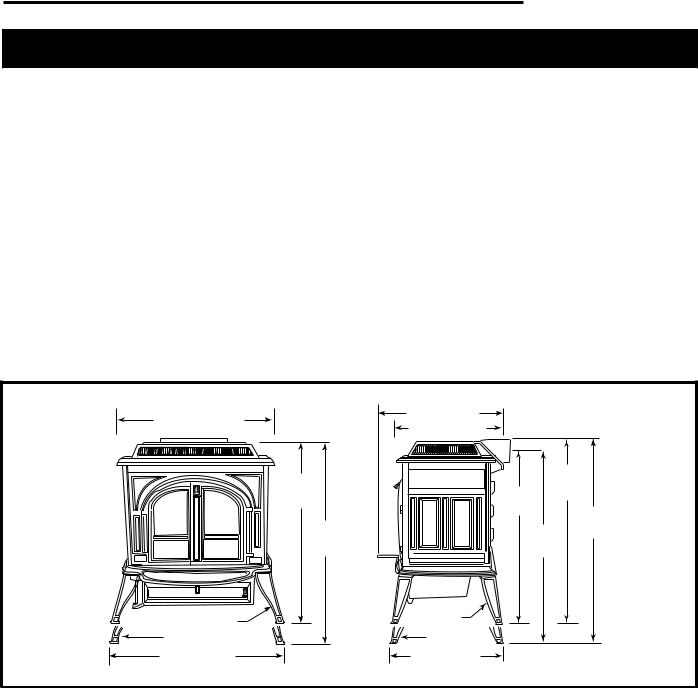
28¹⁄ " (720mm) |
|
23" (584mm) |
|
|
|
20¹⁄ " (520mm) |
|
|
|
|
|
|
|
|
|
31" |
VIGILANT |
|
31³⁄ " |
|
|
28³⁄ " (797mm) |
||
|
(787mm) |
|
||
|
|
|
(721mm) |
33¹⁄ " |
|
|
|
|
|
|
33 ⁄ " |
|
30¹⁄ " |
(851mm) |
|
|
|
||
|
(861mm) |
|
(775mm) |
|
7 ⁄ " Legs |
7 ⁄ " Legs |
10" Legs |
10" Legs |
30" (762mm) |
20" (510mm) |
0898
Fig. 1 Vigilant II dimensions.
2000898 |
3 |
Vermont Castings Vigilant
Installation
Codes and Listings
Conforming to local building codes will be an important part of your planning. Local authorities make the final decision on whether or not an installation will be approved. They need to know that your installation is safe and meets local codes.
The metal label permanently attached to every Vermont Castings stove indicates that the stove has been tested to current UL and ULC standards, and gives the name of the testing laboratory. Clearance and installation information is also printed on the label. In most cases, local authorities will accept the label as evidence that, when the stove is installed according to the information on the label and in this manual, the installation meets codes and can be approved.
However, codes vary in different areas. Be sure to review your installation plans with your local authority before starting the installation. Check with your local Vermont Castings Authorized Dealer for help in providing the necessary information to local officials.
This section will answer clearance and construction questions for almost all installations. Your local Vermont Castings Authorized Dealer will also be able to help. For questions left unanswered, we recommend that you refer to the National Fire Protection Association ANSI/NFPA 211-1988 Standard for Chimneys, Fireplaces, Vents and Solid Fuel Burning Appliances, or in Canada, CSA B365. These standards are the basis for many national codes.
Remember, your local building official makes the final decision on approvals of installations.
CAUTION: Follow all installation and use instructions exactly. Failure to follow instructions may result in a
dangerous situation, including a chimney or house fire.
Chimneys and Draft
Understanding how your chimney contributes to stove operation is essential if you are to obtain optimum performance from your Vigilant Coal Stove. The chimney provides a safe pathway for hot smoke and exhaust gases to exit from the stove, but in addition, the chimney strongly influences the “draft” necessary for operation of your stove.
Draft is the force which produces a flow of warm gases up and out of the chimney, and draws fresh combustion air into the stove. Your Vigilant does not come equipped with “draft”. Draft is the result of a difference in weight (due largely to a difference in temperature) between the gases inside the chimney, and gases outside the chimney. Because gas expands when heated,
warm gases inside the chimney weigh less than cool gases outside. This weight difference creates the pressure necessary to produce and sustain draft.
As the lighter, more buoyant gases rise up the chimney, draft causes a flow of cooler air into the stove. When starting a fire in a cold stove on an unheated chimney, it may be necessary to provide some assistance by igniting several sheets of crumpled newspaper which have been placed in the flue collar area.
There are other factors which influence draft, such as barometric pressure, wind speed and direction, the height, configuration and size of the chimney, and the
airtightness of the home itself.
Improving Draft With Outside Air
In some modern, super-insulated homes, the air necessary for combustion is inadequate due to restricted air infiltration into the dwelling. (Infiltrated air is simply that air which finds its way into a home through various cracks and openings in the foundation, along windows and doors, and at other non-weathertight areas.) If the stove is competing with kitchen or bath exhaust fans for available air, the situation is aggravated further. Where poor draft is the result of a low infiltration rate, opening a ground floor window in the vicinity of the stove, or installing a permanent outside air supply, will often alleviate the problem.
In some areas, bringing air for combustion from outside the home directly to the air inlet of the stove is required for new construction. When the air supply for the fire is brought directly from the outside, it is not affected by variations in air pressure within the house. Improved stove performance often results. An Outside Air Adaptor Kit is available from your local Vermont Castings
Authorized Dealer.
How Draft Affects Stove Performance
A strong draft will allow you to successfully fine-tune the Vigilant’s performance by adjusting the primary air supply to determine the rate of combustion and heat output. With a strong draft, you can restrict the primary air supply and lower the heat output without risk of suffocating the fire.
A strong draft will be maintained by operating your stove so that combustion gases entering the chimney are hot, and stay hot. Air must not be allowed to enter the chimney without first having passed through the stove. Make sure that clean-out doors and thimbles are sealed tightly, and that the chimney is structurally sound.
4 |
2000898 |
Weak draft situations are characterized by smoking and odor problems in the house, low heat output, and difficulty maintaining a fire, especially at low thermostat settings. The reverse situation, overdraft, is rare, but can be recognized by short burn time, poor response when trying to slow down the fire, or by any part of the stove glowing red.
A more common cause of overdraft is inadequate maintenance, such as worn gasket allowing uncontrolled air to enter the stove. Following recommended maintenance procedures will ensure consistent stove performance.
Following the stove manufacturer’s recommendation on both chimney size and height will also help ensure adequate chimney flow capacity. Flow capacity measures the ability of the chimney to evacuate combustion gases quickly. Even the strongest draft cannot overcome an insufficient flow capacity; the result is a back up of combustion gases in the chimney which forces smoke out of chimney connector joints or the stove itself. Remember, the Vigilant and the chimney must function as a unit. For optimum performance, they must be sized properly for each other. Your Vermont Castings Authorized Dealer can help you assess your existing chimney
or plan a new one for best stove operation.
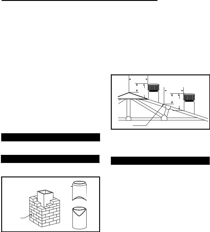
Chimney Guidelines
DO NOT CONNECT TO ANY AIR DISTRIBUTION DUCT OR SYSTEM.
New Chimneys
Both masonry and prefabricated metal chimneys work well.
Prefabricated Doublewall Insulated Chimney

Tile-lined
Masonry
Chimney
ST241
Fig. 2 Chimney types.
A new masonry chimney should be constructed to conform to the standards of your local building code or a recognized national code. Masonry chimneys must be lined with code-approved masonry or pre-cast refractory tiles, stainless steel pipe suitable for use with coal, or a code-approved poured-in-place liner. The chimney must have a tight sealing clean-out door.
Vermont Castings Vigilant
A new prefabricated metal chimney should be one tested and listed for use with solid-fuel burning appliances to the High-Temperature (H.T.) Chimney Standard UL- 103-1985 (2100° F.) and have interior walls especially designed for use with coal-burning stoves. Be sure to follow the chimney manufacturer’s instructions exactly when passing the chimney through a combustible wall or ceiling. Special accessories may be necessary for this type of installation.
The chimney should extend at least 3 feet above the highest point where it passes through a roof, and at least 2 feet higher than any portion of a building within
10 feet.
|
0 To 10' |
|
|
2' Min. 3' |
0 To 10' |
|
Min. |
|
|
|
2' Min. 3' |
|
|
Min. |
|
Reference |
AC617 |
|
Point |
|
Fig. 3 |
The 2’-3’-10’ chimney rule. |
|
For proper draft and good performance, any chimney used with a Vermont Castings wood or coal burning stove should extend at least 16 feet above the flue col-
lar of the stove.
Existing Chimneys
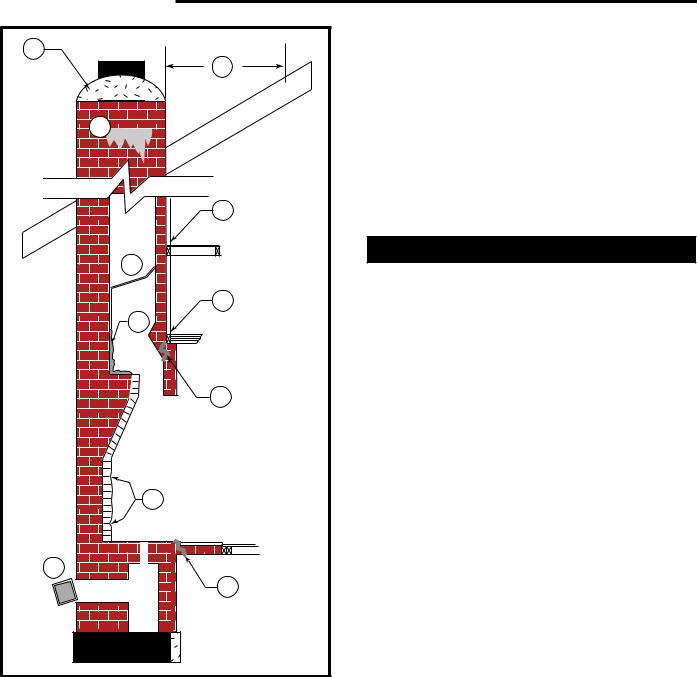
An existing masonry chimney may work well, but be sure to have it carefully inspected before using it. Defects may have gone unnoticed if the chimney previously was used only occasionally. Defects must be repaired before the chimney is used with your stove. If you are not sure that you can make the inspection yourself, your local professional chimney sweep, building inspector, or fire inspector will be able to make the inspection or direct you to someone who can.
The chimney should be thoroughly cleaned before being used with your stove.
First, check to see that the chimney has a lining. Do not use an unlined chimney. Your local Vermont Castings Authorized Dealer or chimney sweep can help you with information about approved chimney lining systems. In addition, look for and repair (if necessary) these defects: (Fig. 4)
A.Improper chimney height and roof clearance; check local building codes for proper construction.
B.Chimney cap deterioration; rebuild.
C.Creosote stains indicate flue damage; inspect and repair.
2000898 |
5 |
Vermont Castings Vigilant
B |
A |
|
|
|
C |
|
E |
|
D |
|
F |
|
G |
|
H |
|
I |
|
J |
|
H |
|
ST562 |
Fig. 6 |
Existing chimney. |
D.Blockage within flue; remove.
E.Improper clearance between chimney and combustible materials. Generally, a clearance of 2” (50 mm.) is required to all combustible walls and framing members; check local codes.
F.Improper clearance between smoke chamber and adjacent framing members; check local codes.
G.Creosote accumulation; chimney needs thorough cleaning.
H.Structural deterioration of the fireplace; must be repaired before use.
I.Loose or broken bricks or mortar; replace and remortar.
J. Loose or broken clean-out door; repair or replace.
Existing masonry chimneys, especially older ones, may have two or more openings through the chimney walls to the same flue. The openings were used to connect stoves in different rooms to the chimney. The unused openings must be sealed with masonry to the thickness of the chimney wall. Unused openings sealed with pie plates or wallpaper are a hazard. In the event of a chimney fire, flames and smoke may be forced out of
these unused thimbles.
DO NOT CONNECT YOUR STOVE OR INSERT TO A CHIMNEY FLUE SERVING ANOTHER APPLIANCE.
Chimney Size
When outfitted with the standard 6” (150 mm) flue collar, The Vigilant II Coal Stove is designed to perform well when vented through flues that have these dimensions:
Prefabricated
Round Liner, I.D. |
6” (150 mm) |
Masonry |
|
Square Liner |
8” x 8” (nominal) |
Rectangular Liner |
7” x 11” (nominal) |
Round Liner |
6” (inside dimensions) |
A Vigilant II Coal Stove equipped with the optional 8” (200 mm) flue collar is designed to perform well when vented through flues that have these dimensions:
Prefabricated |
|
Round Liner |
8” (inside dimension) |
Masonry |
|
Square Liner |
8” x 8” (nominal) |
Rectangular Liner |
8” x 12” (nominal) |
Round Liner |
8” (inside dimensions) |
CHIMNEYS WITH LINERS LARGER THAN 8” X 12” MAY EXPERIENCE RAPID COOLING OF COMBUS-
TION GASES AND REDUCTION IN DRAFT, ESPECIALLY IF THEY ARE LOCATED OUTSIDE THE HOME.
These large chimneys may need to be insulated or the flues re-lined for good stove performance. Vermont Castings offers chimney lining accessories to help make the connection between stainless steel chimney liners and our stoves and fireplaces.
If you are planning to vent a small stove into a large flue, particularly an exterior masonry flue, you may find it necessary to insulate the chimney, reline the chimney, or operate the stove with the damper open to maintain
high flue temperatures.
6 |
2000898 |
Clearances
Your stove and chimney connector will radiate energy in all directions when in operation. An important part of planning a safe installation is to be sure combustible materials near your stove do not overheat due to inadequate clearance.
Clearance is the distance between your stove (or chimney connector) and nearby walls, ceiling, and floors, as well as other combustible materials. Correct clearance must also be maintained to moveable items, such as furniture, newspapers, or clothes left to dry near the stove. Keep all combustibles a considerable distance away from the stove; 48” is a good minimum clearance. Installing your Vigilant to the tested clearance and keeping those clearance areas empty assures that nearby surfaces will not overheat.
Clearances must be large enough so that furniture and other combustibles near your stove will not overheat and catch fire. Wood framing that is part of a wall
or floor will dry as it ages, and its ignition point (the temperature at which it will start to burn) will be lowered. The change may take place slowly over a period of many years, or more quickly if the wood is near a source of heat such as a stove.
Your Vermont Castings Vigilant II Coal Stove has been carefully and thoroughly tested by independent testing laboratories to determine safe clearances. During testing, heat sensors installed in all surfaces near the stove and chimney connector, including floors and ceilings, show the temperatures reached during a variety of combustion situations. Clearance distances are accepted only when the sensors show the stove is far enough from nearby surfaces to meet strict UL or ULC
standards.
Using The Clearance Chart
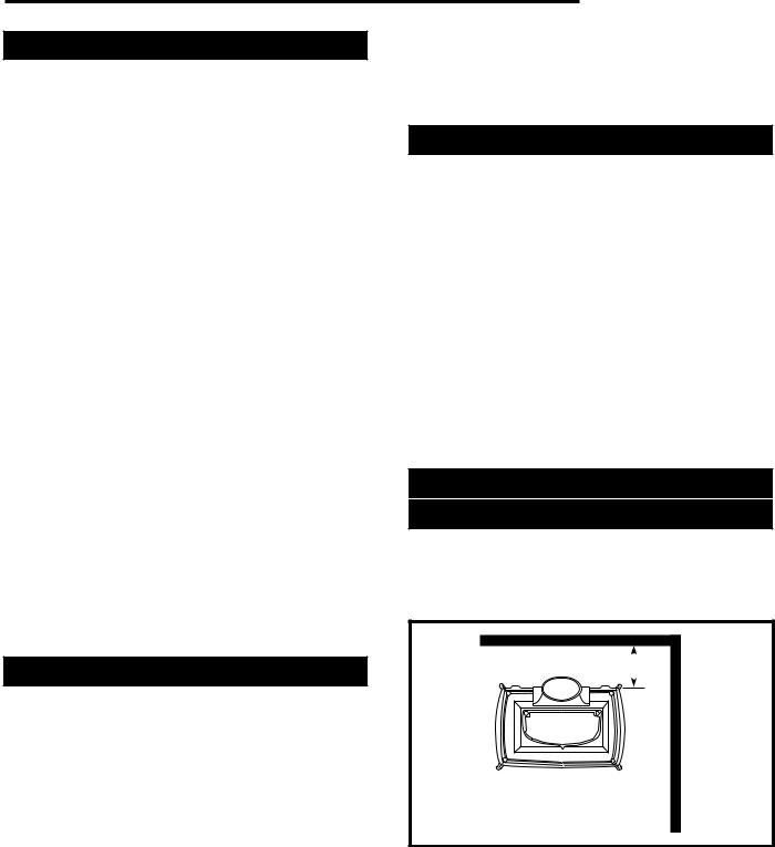
If your stove will be parallel to the wall behind it (parallel installation), use the columns of the chart labelled “side” and “rear”. If your stove will be installed in a corner
(corner installation), use the columns labelled “corner”. Your stove will be in either a parallel or a corner installation, not both. Use only the part of the chart that applies to your installation. Note: Side clearances do not apply to corner installations.
Measure clearance between the edge of the stove’s top plate and the nearby combustible surface. For most common installations, when the stove has the proper clearance from nearby surfaces, the chimney connector will also have the proper clearance. However, installations vary. It is important to double check all installations for proper chimney connector clearance, as well
as stove clearance.
Vermont Castings Vigilant
The clearance distance must be empty except for noncombustible heat shields. Air flowing between the stove (and/or chimney connector) and nearby shields carries away heat. Do not block the air flow by filling this empty space with any insulating material.
Clearance Reductions
When no shields are used, empty space alone provides protection against overheating. When shields are used, it is usually possible to reduce the required clearance, as the shields offer additional protection.
Stove shields and connector shields (used only on single-wall connectors) attach directly to the stove or connector. Wall shields attach to wall surfaces. Combinations of the these shield types may be used.
When shields are attached to the stove or chimney connector, they are mounted 1” - 2” away from the stove or connector surface on non-combustible spacers. The shiny shield surface facing the heat source must be left unpainted, enabling it to reflect heat back towards the stove or connector and away from the wall.
The greatest clearance reductions result from using both stove and chimney connector shields in conjunc-
tion with walls which are protected with wall shields.
Unprotected Walls
Clearances With No Heat Shields
If the Vigilant is installed parallel to the rear wall (parallel installation) and no shields are used, the stove must be at least 20” (510 mm) from the wall behind it, and at least 18” (460 mm) from walls beside it.
20" (510mm)

 18"
18"  (460mm)
ST683
Fig. 5 Minimum clearances, parallel installation, no heat shield.
2000898 |
7 |
Vermont Castings Vigilant
If the Vigilant is installed in a corner (corner installation) and no shields are used, the corners of the stove must be at least 16” (410 mm) from nearby walls. (Fig. 6)
16" (410mm)
16"
(410mm)
ST684
Fig. 6 Minimum clearance, corner installation, no heat shield.
Measure these distances from the edge of the top plate of the stove nearest the wall to the combustible part of the wall.
Unshielded single wall chimney connectors must be a minimum of 17” (430 mm) from the wall or ceiling.
Clearances With Only the
Stove Rear Heat Shield
If you install a Vigilant with a rear heat shield in a parallel installation, but use no chimney connector heat shields, different clearances will be required for top-exit- ing and rear-exiting stoves.
For top-exiting stoves, clearance to the rear wall is determined by heat from the unshielded chimney connector, not heat from the stove. Stove placement must ensure that the unshielded connector cannot overheat the rear wall. Reminder: Use the Flue Collar Heat Shield (#140-0924) included with the Rear Heat Shield #0175 to protect the area directly behind the flue collar. Rear clearance must be a minimum of 20” (510 mm), measured from the edge of the stove top to the rear wall. Side clearance is determined by heat from the stove. It must be a minimum of 18” (460 mm) , measured from the edge of the stove top to the combustible component of the unprotected wall. (Fig. 7)
20" (510mm)

 18"
18"  (460mm)
ST685
Fig. 7 Minimum clearance, parallel installation, rear heat shield.
For rear-exiting stoves, both rear and side clearances are determined by the heat from the stove (provided that the connector does not pass near a combustible surface).
The rear heat shield protects the wall behind the stove so that clearance may be reduced to 13” (330 mm), measured from the rear edge of the stove’s top plate to the combustible part of the wall. Side clearance remains the same — 18”, measured from the edge of the stove top to the side wall. (Fig. 8)
13" (330mm) |

 18"
18"  (460mm)
ST686
Fig. 8 Minimum clearance, rear exit, rear heat shield.
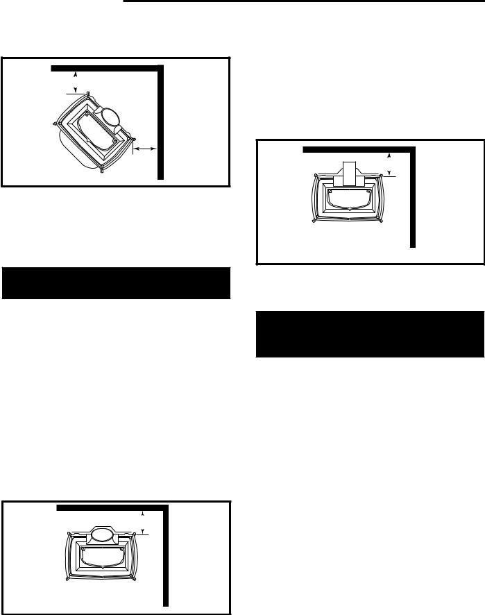
For corner instllations, the clearance is 16”, measured from the corners of the stove perpendicular to the wall.
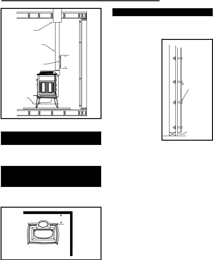
Clearances With Double-wall Connectors,
Or Single-wall Connectors And Connector
Heat Shields
The Vigilant II Coal Stove listing includes using singlewall or double-wall chimney connectors. The rows of the clearance chart labelled “Chimney Connector Clearance” give clearances measured from the chim-
ney connector to nearby walls and ceilings. (“Ceilings” is emphasized to remind you that ceiling clearance is an important clearance that is sometimes overlooked.) Be sure to double-check chimney connector clearances before completing your installation.
Reminder: For top-exiting stoves using a rear heat shield, install the Flue Collar Heat Shield (#140-0924), included with the Rear Heat Shield #0175, to protect the area directly behind the flue collar. Instructions are included with the heat shield package.
When using a chimney connector heat shield on a single-wall connector, it may only extend 24” (610 mm) above the flue collar. The shield must come down to meet the top of the Flue Collar Heat Shield. (Fig. 9)
8 |
2000898 |
Prefabricated |
|
Chimney |
|
Single-wall |
|
Chimney Connector |
|
Chimney |
24" |
Connector |
(610mm) |
Heat Shield |
Max. |
|
VIGILANT |
Bottom |
|
Heat |
|
Shield |
|
|
ST687 |
Fig. 9 Chimney connector heat shields may be used to reduce clearances when single-wall connectors are used.
Clearances With Double Wall Chimney Connectors And Rear Stove Heat Shields
When a rear heat shield is used on the stove and a double wall chimney connector is used, the rear clearance is 15¹⁄ " (395 mm) and the chimney connector clearance is 12" (300 mm).
Clearances With Single-wall Chimney
Connectors, Connector Shields And Rear
Stove Heat Shields
Use of both stove and chimney connector heat shields, on single-wall connectors, in top-exiting installations reduces the required clearance. (Fig. 10)
13" (330mm)

 18"
18"  (460mm)
ST688
Fig. 10 Minimum clearance, chimney connector heat shield, rear heat shield.
Vermont Castings Vigilant
Protected Walls
A properly constructed wall shield may be used to change an unprotected wall to a protected wall, allowing the clearances given in the right half of the Clearance Chart.
Wall shields should be constructed of 24 gauge or heavier sheetmetal, 1/2” noncombustible insulation board, or common brick laid on flat (3¹⁄ " side down). Shields must be spaced out from the combustible wall or ceiling 1" on noncombustible spacers. The spacers should not be directly behind the stove or chimney connector.
Air must be able to flow between the wall and the shield. At least one-half (50%) of the bottom 1" of the shield should be open and the shield must stop 1" from the ceiling. Protect the top opening with metal screening to prevent objects from falling behind the shield.
 Air Flow
 Wall Shield
 Stud Wall Fram-
ing
 Noncom-
bustible
Spacer and
Fasteners
 Drywall
Air Flow
ST248
Fig. 11 Wall shield construction.
Rear wall shields must extend 18" above the top of the stove or to within 1" of the ceiling, must be centered behind the stove, and must be a minimum of 48" (1220 mm) wide by 48" high.
Side wall shields must be 48" (1220 mm) wide by 44" high, and must extend 15" (380 mm) beyond the front of the stove as measured from a point on the wall that is on the same plane as the door glass.
2000898 |
9 |
 Loading...