


 Loading...
WANsuite® 5370
Reference Manual
September 2002 34-00310.D
i

Copyright Notice |
Copyright © 2002 Verilink Corporation. All rights reserved. No part of this publication may be |
|
reproduced, transmitted, transcribed, stored in a retrieval system, or translated into any language |
|
in any form by any means without the written permission of Verilink. |
|
Manual Reorder # 34 -00310.D |
|
September 2002 |
Trademarks |
Verilink® and WANsuite® are registered trademarks of the Verilink Corporation. FrameStart™, |
|
and ServiceAware™ are trademarks of the Verilink Corporation. |
|
All other brand and product names used herein are trademarks or registered trademarks of their |
|
respective manufacturers. |
Documentation |
This document does not create any express or implied warranty about Verilink or about its prod- |
Disclaimer |
ucts or services. Verilink’s sole warranty is contained in its product warranty. The end-user doc- |
|
umentation is shipped with Verilink’s products and constitutes the sole specifications referred to |
|
in the product warranty. Verilink has made reasonable efforts to verify that the information con- |
|
tained herein is accurate, but Verilink assumes no responsibility for its use or for any infringe- |
|
ment of patents or other rights of third parties that may result. The customer is solely |
|
responsible for verifying the suitability of Verilink’s products for its use. Specifications are sub- |
|
ject to change without notice. |
Warranty |
Verilink's product warranty is included at the back of this document. |
FCC Requirements |
Changes or modifications to this unit not expressly approved by the party responsible for |
|
compliance could void the user’s authority to operate the equipment. |
|
This device complies with Part 15 of the FCC rules. Operation is subject to the following two |
|
conditions: |
|
1 This device may not cause harmful interference. |
|
2 This device must accept any interference received, including interference that may cause |
|
undesired operation. |
|
This equipment has been tested and found to comply with the limits for a Class A digital device, |
|
pursuant to Part 15 of FCC Rules. These limits are designed to provide reasonable protection |
|
against harmful interference when the equipment is operated in a commercial environment. This |
|
equipment generates, uses, and can radiate radio frequency energy and if not installed and used |
|
in accordance with the instruction manual, may cause harmful interference to radio communica- |
|
tions. Operation of this equipment in a residential area is likely to cause harmful interference. |
|
The user will be required to correct the interference at his own expense. |
|
This equipment complies with Part 68 of the FCC Rules. On the rear or bottom of this unit is a |
|
label that contains the FCC registration number and other information. If requested, provide this |
|
information to the telephone company. |
|
1 All direct connections to DDS lines must be made using standard plugs and jacks (compliant |
|
with Part 68). |
|
2 If the unit appears to be malfunctioning, it should be disconnected from the DDS lines until |
|
the source of trouble is determined to be your equipment or the telephone line. If your |
|
equipment needs repair, it should not be reconnected until it is repaired. |
|
3 The unit has been designed to prevent harm to the DDS network. If the telephone company |
|
finds that the equipment is exceeding tolerable parameters, it can temporarily disconnect |
|
service. In this case, the telephone company will give you advance notice, if possible. |
|
4 Under FCC rules, no customer is authorized to repair this equipment, regardless of warranty |
|
status. |
|
5 If the telephone company alters its equipment in a manner that will affect the use of this |
|
device, it must give you advance warning so that you can have the opportunity for |
|
uninterrupted service. You will be advised of your right to file a complaint with the FCC. |
ii W A N s u i t e 5 3 7 0

6In the event of equipment malfunction, all repairs should be performed by our company or an authorized agent. It is the responsibility of users requiring service to report the need for service to our company or to one of our authorized agents.
Canadian Emissions This digital apparatus does not exceed the Class A limits for radio noise emissions from digital Requirements apparatus set out in the Radio Interference Regulations of the Canadian Department of Commu-
nications.
WARNING: For the DC powered units only, end users should use existing battery sources or a CSA certified power supply.
Le présent appareil numérique n’émet pas de bruits radioélectriques dépassant les limites applicables aux appareils numériques (de la class A) prescrites dans le Règlement sur le brouillage radioélectrique edicté par le ministère des Communications du Canada.
Safety Precautions When handling this equipment, follow these basic safety precautions to reduce the risk of electric shock and injury:
•Follow all warnings and instructions marked on the product and in the manual.
•Unplug the hardware from the wall outlet before cleaning. Do not use liquid cleaners or aerosol cleaners. Use a slightly damp cloth for cleaning.
•Do not place this product on an unstable cart, stand, or table. It may fall, causing serious damage to the product.
•Slots in the unit are provided for ventilation to protect it from overheating. These openings must not be blocked or covered. Never place this product near a radiator or heat register.
•This product should be operated only from the type of power source indicated on the marking label and manual. If you are unsure of the type of power supply you are using, consult your dealer or local power company.
•Do not allow anything to rest on the power cord. Do not locate this product where the cord interferes with the free movement of people.
•Do not overload wall outlets and extension cords, as this can result in fire or electric shock.
•Never push objects of any kind into the unit. They may touch dangerous voltage points or short out parts that could result in fire or electric shock. Never spill liquid of any kind on this equipment.
•Unplug the equipment from the wall outlet and refer servicing to qualified service personnel under the following conditions:
•When the power supply cord or plug is damaged or frayed.
•If liquid has been spilled into the product.
•If the product has been exposed to rain or water.
•If the product has been dropped or if the housing has been damaged.
F C C R e q u i r e m e n t s |
iii |
iv W A N s u i t e 5 3 7 0
Table of Contents
Preface
About this Manual ................................................................................................................................ |
xi |
Manual Organization ...................................................................................................................... |
xi |
Typographic Conventions ............................................................................................................. |
xii |
Customer Service and Technical Support ............................................................................................ |
xii |
Support from Your Network Supplier ........................................................................................... |
xii |
Support from Verilink ................................................................................................................... |
xii |
Telephone ............................................................................................................................... |
xii |
E-mail .................................................................................................................................... |
xiii |
Internet ................................................................................................................................... |
xiii |
Returning a Unit to Verilink ............................................................................................................... |
xiii |
Chapter 1 About the WANsuite 5370
Introduction ......................................................................................................................................... |
1-1 |
Features of the WANsuite 5370 ......................................................................................................... |
1-3 |
Performance ................................................................................................................................. |
1-3 |
SNMP Management ..................................................................................................................... |
1-3 |
Intelligent WAN Access Architecture ......................................................................................... |
1-3 |
Optional Advanced Network Management .................................................................................. |
1-4 |
About FrameStart Technology ........................................................................................................... |
1-4 |
WANsuite 5370 Overview and Advantages ....................................................................................... |
1-5 |
Features Summary .............................................................................................................................. |
1-5 |
Front Panel .......................................................................................................................................... |
1-7 |
Rear Panel Connections ...................................................................................................................... |
1-9 |
Supervisory Port ........................................................................................................................... |
1-9 |
Auxiliary Port ............................................................................................................................. |
1-10 |
10/100 Ethernet .......................................................................................................................... |
1-10 |
Ethernet LED Indicators ...................................................................................................... |
1-10 |
Serial Interfaces .......................................................................................................................... |
1-10 |
Network Interface ....................................................................................................................... |
1-11 |
Power Connection ..................................................................................................................... |
1-11 |
Power Failure ....................................................................................................................... |
1-12 |
Chapter 2 Installation
Unpacking and Inspection .................................................................................................................. |
2-1 |
Supplied Materials .............................................................................................................................. |
2-1 |
Installation Wizard .............................................................................................................................. |
2-2 |
v
Chapter 3 Web Server Interface
Web Server Access ............................................................................................................................. |
3-1 |
Layout of Interface Screens ......................................................................................................... |
3-2 |
Unit Screen ......................................................................................................................................... |
3-2 |
Interfaces ............................................................................................................................................. |
3-4 |
Network Screen ............................................................................................................................ |
3-4 |
Error Status and Alarm Thresholds Table ............................................................................. |
3-5 |
Serial 1 and Serial 2 Screens ........................................................................................................ |
3-6 |
Current Pin Status .................................................................................................................. |
3-9 |
DTR Alarm Control and Status Table ................................................................................... |
3-9 |
Auxiliary Screen ........................................................................................................................... |
3-9 |
Current Pin Status ................................................................................................................ |
3-10 |
DTR Alarm Control and Status Table ................................................................................. |
3-10 |
10/100 Ethernet (IP Service Details) Screen .............................................................................. |
3-11 |
Supervisory Screen ..................................................................................................................... |
3-13 |
Current Pin Status ................................................................................................................ |
3-14 |
DTR Alarm Control and Status Table ................................................................................. |
3-14 |
Services Screen ................................................................................................................................. |
3-14 |
Adding a Service ................................................................................................................. |
3-15 |
Data Line Monitor Configuration Table .................................................................................... |
3-15 |
Service Details Screen ................................................................................................................ |
3-17 |
Interface Details Button ....................................................................................................... |
3-18 |
Type Details Button ............................................................................................................. |
3-19 |
Delete Service Button .......................................................................................................... |
3-19 |
Frame Relay Service Details Screen .......................................................................................... |
3-19 |
Status and Alarms Table ...................................................................................................... |
3-23 |
Frame Relay Port Statistics Screen ...................................................................................... |
3-24 |
SCADA Details Screen .............................................................................................................. |
3-26 |
PPP Service Details Screen ........................................................................................................ |
3-27 |
Parameters To Negotiate ..................................................................................................... |
3-29 |
PPP Statistics ....................................................................................................................... |
3-30 |
PAP Table ............................................................................................................................ |
3-31 |
CHAP Table ........................................................................................................................ |
3-32 |
IP Services Screen ...................................................................................................................... |
3-33 |
Applications ...................................................................................................................................... |
3-33 |
Endpoint Table Screen ............................................................................................................... |
3-33 |
Endpoint Details Screen ...................................................................................................... |
3-34 |
Endpoint Service Details Screen ......................................................................................... |
3-37 |
DLCI Details Screen ............................................................................................................ |
3-37 |
Service Aware Screen ................................................................................................................ |
3-42 |
Rule Details Screen ............................................................................................................. |
3-43 |
Traffic Meter Statistics Screen ............................................................................................ |
3-44 |
SNMP Details Screen ................................................................................................................. |
3-45 |
Diagnostics Screen ..................................................................................................................... |
3-46 |
Test Details Screen .............................................................................................................. |
3-47 |
Trap Log Screen ......................................................................................................................... |
3-49 |
Top N Details (Top Talkers) Screen .......................................................................................... |
3-50 |
IP Gateway Screen ..................................................................................................................... |
3-51 |
vi W A N s u i t e 5 3 7 0
OSPF Parameters ................................................................................................................. |
3-52 |
Circuit Table Screen ............................................................................................................ |
3-53 |
Static Route Table Screen .................................................................................................... |
3-55 |
ARP Table Screen ............................................................................................................... |
3-58 |
Trusted Neighbor Table Screen ........................................................................................... |
3-60 |
Area Table Screen ............................................................................................................... |
3-61 |
Virtual Link Table Screen ................................................................................................... |
3-63 |
TCP Server ................................................................................................................................. |
3-64 |
TCP Server Details Screen .................................................................................................. |
3-64 |
Network Address Translation (NAT) ......................................................................................... |
3-66 |
NAT Details Screen ............................................................................................................. |
3-67 |
Dynamic Host Configuration Protocol (DHCP) ........................................................................ |
3-72 |
DHCP Server Details Screen ............................................................................................... |
3-73 |
Bridge ......................................................................................................................................... |
3-77 |
Simple Mail Transfer Protocol (SMTP) ..................................................................................... |
3-81 |
Encryption .................................................................................................................................. |
3-81 |
Utilities ............................................................................................................................................. |
3-82 |
Upload/Save ............................................................................................................................... |
3-82 |
Password .................................................................................................................................... |
3-83 |
Log Out ...................................................................................................................................... |
3-83 |
In-band Management ................................................................................................................. |
3-84 |
Use of Connected Local Router ........................................................................................... |
3-84 |
Use of Local WANsuite 5370 as a Gateway ....................................................................... |
3-84 |
Chapter 4 VT100 Interface
Introduction ......................................................................................................................................... |
4-1 |
Accessing the VT100 Interface ................................................................................................... |
4-1 |
Screen Components ...................................................................................................................... |
4-1 |
Cursor Controls ............................................................................................................................ |
4-2 |
Field Types ................................................................................................................................... |
4-2 |
Menu Structure ............................................................................................................................. |
4-3 |
System Screen ..................................................................................................................................... |
4-4 |
Maintenance Reset ....................................................................................................................... |
4-5 |
Save and Restart ........................................................................................................................... |
4-6 |
Interfaces Screen ................................................................................................................................. |
4-6 |
Network Config Screen ................................................................................................................ |
4-7 |
Error Status and Alarm Thresholds Table ............................................................................. |
4-7 |
Serial 1 and Serial 2 Screens ........................................................................................................ |
4-8 |
Auxiliary Configuration Screen ................................................................................................. |
4-11 |
10/100 Ethernet (IP Details) Screen ........................................................................................... |
4-12 |
Supervisory Configuration Screen ............................................................................................. |
4-14 |
Service Table Screen ........................................................................................................................ |
4-16 |
Data Line Monitor ...................................................................................................................... |
4-16 |
Service Details Screen ......................................................................................................... |
4-19 |
Frame Relay Service Details Screen .......................................................................................... |
4-20 |
Frame Relay Statistics Screen ............................................................................................. |
4-24 |
PPP Service Details Screen ........................................................................................................ |
4-26 |
vii
Parameters To Negotiate ..................................................................................................... |
4-27 |
PPP Statistics ....................................................................................................................... |
4-28 |
PAP Table ............................................................................................................................ |
4-29 |
CHAP Table and Details Screens ........................................................................................ |
4-30 |
IP Service Details Screen ........................................................................................................... |
4-30 |
SCADA Service Details Screen ................................................................................................. |
4-30 |
Applications ...................................................................................................................................... |
4-32 |
Endpoint Table Screen ............................................................................................................... |
4-32 |
Endpoint Details Screen ...................................................................................................... |
4-33 |
Endpoint Service Details Screen ......................................................................................... |
4-35 |
DLCI Details Screen ............................................................................................................ |
4-36 |
DLCI Statistics Screen ......................................................................................................... |
4-39 |
DLCI Table Screen .............................................................................................................. |
4-40 |
Service Aware Screen ................................................................................................................ |
4-41 |
Rule Configuration Screen .................................................................................................. |
4-41 |
Traffic Meter Statistics Screen ............................................................................................ |
4-43 |
SNMP Details Screen ................................................................................................................. |
4-44 |
Diagnostics Screen ..................................................................................................................... |
4-44 |
Test Details Screen .............................................................................................................. |
4-45 |
Trap Log Screen ......................................................................................................................... |
4-47 |
Top Talkers Screen .................................................................................................................... |
4-48 |
IP Gateway Screen ..................................................................................................................... |
4-49 |
RIP Parameters .................................................................................................................... |
4-50 |
OSPF Parameters ................................................................................................................. |
4-50 |
Circuit Table Screen ............................................................................................................ |
4-51 |
Static Route Table Screen .................................................................................................... |
4-53 |
Static ARP Table Screen ..................................................................................................... |
4-56 |
Trusted Neighbors Screen ................................................................................................... |
4-57 |
Area Table Screen ............................................................................................................... |
4-58 |
Virtual Link Table Screen ................................................................................................... |
4-60 |
TCP Server ................................................................................................................................. |
4-62 |
TCP Server Screen ............................................................................................................... |
4-62 |
Network Address Translation (NAT) ......................................................................................... |
4-64 |
NAT Details Screen ............................................................................................................. |
4-65 |
Dynamic Host Configuration Protocol (DHCP) ........................................................................ |
4-71 |
DHCP Server Details Screen ............................................................................................... |
4-72 |
Bridge ......................................................................................................................................... |
4-75 |
Simple Mail Transfer Protocol (SMTP) ..................................................................................... |
4-79 |
Encryption .................................................................................................................................. |
4-80 |
Chapter 5 Front Panel LCD Interface
Introduction ......................................................................................................................................... |
5-1 |
Description of Front Panel ........................................................................................................... |
5-1 |
LCD Front Panel Operation ................................................................................................................ |
5-3 |
Password ...................................................................................................................................... |
5-3 |
Interface Conventions .................................................................................................................. |
5-4 |
Menu Title ............................................................................................................................. |
5-4 |
Menu Element ........................................................................................................................ |
5-4 |
viii W A N s u i t e 5 3 7 0
Information Element .............................................................................................................. |
5-4 |
Cursor .................................................................................................................................... |
5-5 |
Main Menu .......................................................................................................................................... |
5-5 |
Alarms Menu ................................................................................................................................ |
5-5 |
Network Alarm Stats Menu ................................................................................................... |
5-6 |
Serial Alarm Menu ................................................................................................................ |
5-7 |
Alarms Reset Timer ............................................................................................................... |
5-7 |
Reset Alarms .......................................................................................................................... |
5-7 |
Maintenance Menu ....................................................................................................................... |
5-7 |
Network Maintenance Menu ................................................................................................. |
5-7 |
Serial 1 and 2 Maintenance Menu ......................................................................................... |
5-8 |
Configuration Menu ................................................................................................................... |
5-10 |
TCP/IP Configuration Menu ............................................................................................... |
5-10 |
Network Configuration Menu ............................................................................................. |
5-11 |
Serial 1 and 2 Configuration Menu ..................................................................................... |
5-12 |
Supervisory Configuration Menu ........................................................................................ |
5-14 |
Auxiliary Configuration Menu ............................................................................................ |
5-15 |
Utilities Menu ............................................................................................................................. |
5-16 |
Maintenance Reset ............................................................................................................... |
5-16 |
Set Password ........................................................................................................................ |
5-16 |
LCD E/D .............................................................................................................................. |
5-17 |
Log Out ...................................................................................................................................... |
5-17 |
Appendix A Specifications
Network Interface .............................................................................................................................. |
A-1 |
Serial 1 and Serial 2 Interface ............................................................................................................ |
A-1 |
Auxiliary Port .................................................................................................................................... |
A-1 |
Management Interfaces ...................................................................................................................... |
A-1 |
Supervisory Port .......................................................................................................................... |
A-1 |
10/100 Ethernet ........................................................................................................................... |
A-2 |
Diagnostics ........................................................................................................................................ |
A-2 |
Alarms ................................................................................................................................................ |
A-2 |
Power ................................................................................................................................................. |
A-2 |
Mechanical ......................................................................................................................................... |
A-2 |
Environmental .................................................................................................................................... |
A-2 |
Frame Relay Statistics Collected in 96 15-minute Intervals ............................................................. |
A-2 |
PPP Statistics Collected in 96 15-minute Intervals ........................................................................... |
A-3 |
Industry Listings ............................................................................................................................... |
A-3 |
Standards ............................................................................................................................................ |
A-3 |
Ordering Information ......................................................................................................................... |
A-4 |
Optional Equipment ........................................................................................................................... |
A-4 |
Connector Pin Assignments ............................................................................................................... |
A-6 |
ix
Serial Interface Pin Assignments, DTE Mode (Packet use only) .............................................. |
A-6 |
Serial Interface Pin Assignments, DCE Mode ........................................................................... |
A-7 |
Ethernet Connection Pin Assignments ........................................................................................ |
A-7 |
Network Interface Pin Assignments ............................................................................................ |
A-8 |
Supervisory and Auxiliary Port Pin Assignments ....................................................................... |
A-8 |
Appendix B SNMP Agent
Introduction ......................................................................................................................................... |
B-1 |
SNMP Configuration Parameters ....................................................................................................... |
B-1 |
SNMP MIBs ....................................................................................................................................... |
B-1 |
SNMP Trap Configuration ................................................................................................................. |
B-2 |
Generic MIB Loading Instructions ................................................................................................... |
B-10 |
x W A N s u i t e 5 3 7 0
PREFACE
About this Manual
This reference guide for the Verilink WANsuite 5370 intelligent integrated access device (I2AD) describes unit features and specifications, configuration, and cabling. It is not a users guide containing step-by-step procedures. Rather, this manual is designed to be used as a reference regarding commands, interface ports, configuration parameters, and other specific information about the WANsuite 5370.
Manual Organization
The chapters and appendices in this manual are arranged for quick reference when you need it. You do not have to read previous chapters to understand the subsequent chapters. Appendices are designed to complement the main chapters.
•
•
•
•
•
Chapter 1, "About the WANsuite 5370" – This chapter describes product features and capabilities.
Chapter 2, "Installation" – This chapter describes unit port connections and powering information.
Chapter 3, "Web Server Interface" – This chapter describes the menu screens and configuration parameters accessed through the Web server interface.
Chapter 4, "VT100 Interface" − This chapter describes the menu screens and configuration parameters accessed through the VT100 interface.
Chapter 5, "Front Panel LCD Interface" – This chapter describes the methods and options for configuring and controlling the unit through the front panel LCD interface.
•Appendix A, "Specifications" – This appendix defines the specifications for the WANsuite 5370. In addition, this section provides ordering information and all the connector pin assignments for the interfaces on the back of the WANsuite 5370 units.
•Appendix B, "SNMP Agent" – This appendix defines which Management Information Base (MIB) files are supported by the WANsuite 5370 SNMP agent. In addition, instructions are provided for loading these MIB files into most SNMP management stations.
P r e f a c e xi

Typographic Conventions
The following table lists the conventions used throughout this guide.
Convention Description
A Notice calls attentions to important features or instructions.
A Caution alerts you to serious risk of data loss or other results that may cause you or the unit trouble if the warning is not heeded.
A Warning alerts you to the risk of serious damage to the unit or injury and possible death to the end user.
Customer Service and Technical Support
Verilink provides easy access to customer support information through a variety of services. This section describes these services.
Support from Your Network Supplier
If assistance is required, contact your network supplier. Many suppliers are authorized Verilink service partners who are qualified to provide a variety of services, including network planning, installation, hardware maintenance, application training, and support services. When you contact your network supplier for assistance, have the following information ready:
•
•
•
Diagnostic error messages
A list of system hardware and software, including revision levels
Details about recent configuration changes, if applicable
Support from Verilink
If you are unable to receive support from your network supplier or want to contact us directly, Verilink offers worldwide customer support by telephone, e-mail, and through Verilink’s Internet Web site.
Telephone
Customer support is available by telephone 24 hours a day, 7 days a week. To speak directly with a Verilink customer service representative, you may dial one of the following numbers:
•Sales and Marketing: 800-VERILINK (837-4546)
•Technical Support: 800 -285- 2755 (toll-free)
256-327-2255 (local)
xii |
W A N s u i t e 5 3 7 0 |

You can request sales and marketing information or pose a technical support question about your Verilink product by contacting us at the e-mail addresses provided below. Verilink will respond to e-mailed requests for support during regular business hours (8–5 CST, Monday–Friday).
•Sales and Marketing: info@verilink.com
•Technical Support: support@verilink.com
Internet
Visit Verilink’s Web site to access the latest Verilink product information, technical publications, news releases, contact information, and more:
http://www.verilink.com
If this reference manual is revised to reflect code changes or other updates, the most recent version will be posted to the Verilink Web site.
Returning a Unit to Verilink
If for any reason you must return your Verilink product, it must be returned with the shipping prepaid, and packaged to the best commercial standard for electronic equipment. Verilink will pay shipping charges for delivery on return. You are responsible for mode and cost of shipment to Verilink.
You must have a Return Material Authorization (RMA) number marked on the shipping package. Products sent to Verilink without RMA numbers will be returned to the sender unopened, at the sender’s expense.
A product sent directly to Verilink for repair must first be assigned an RMA number. You may obtain an RMA number by calling Customer Service at 800-926-0085, extension 2282 or 2232.
When calling Verilink for an RMA, please have the following information available:
•
•
•
Model number and serial number for each unit
Reason for return and symptoms of problem
Purchase order number to cover charges for outof -warranty items
•Name and phone number of person we can contact if we have questions about the unit(s)
The address for you to use when returning a unit to Verilink will be provided when the RMA is issued. The standard delivery method for return shipments is Standard Ground for domestic returns and International Economy for international returns (unless otherwise specified).
P r e f a c e xiii
xiv |
W A N s u i t e 5 3 7 0 |

C H A P T E R
1
ABOUT THE WANSUITE 5370
Introduction
The telecommunications network service market is rapidly changing, where network monitoring, control, and higher performance in packet processing are not only expected, but demanded, at competitive price points. WAN access architecture − a highly flexible and powerful architecture that can meet the needs of many different customers in many different applications. Because it is so flexible, WANsuite products will continually evolve, offering our customers cutting-edge features at competitive prices.
Verilink’s WANsuite 5370 is a feature-rich, intelligent integrated access device (I2AD) specifically designed with the flexibility and intelligence required to meet the needs of today’s expanding Supervisory Control and Data Acquisition (SCADA) applications. SCADA systems monitor, manage, and control distribution facilities. Power, water, gas, and other utility companies use SCADA to remotely read meters and to monitor and control valves or relays. A SCADA system can dramatically increase a facility’s efficiency and reduce operating costs by eliminating the need for expensive “Truck Rolls.” Today’s SCADA environment demands higher bandwidths than older, more traditional, analog modem systems. Frame Relay networks have cost effectively responded to that demand.
The WANsuite 5370 is a single-network-port, service-aware DDS DSU with two serial ports software-configurable for RS-232, EIA-530, or V.35 electrical connections. Additionally, an asynchronous Supervisory port, with an RS-232 electrical connection only, supports PPP, tty, and SCADA. An asynchronous Auxiliary port, also RS-232, supports PPP and SCADA. The WANsuite 5370 also has a 10/100Base-T Ethernet interface, four status LEDs, and three input control keys.
All of WANsuite 5370’s installation, performance configuration, traffic monitoring, alarm reporting, and diagnostic capabilities can be configured through the unit’s embedded Web server interface (WANsight™) using Microsoft® Internet Explorer™ 5. x. The Web server interface can be accessed locally through the Ethernet port or the Supervisory port, or remotely through the Network port. Especially advantageous is WANsuite’s advanced
A b o u t t h e W A N s u i t e 5 3 7 0 1-1
monitoring and control capability that gives network administrators the ability to plan future capacity requirements. To extend the WANsuite 5370’s functionality even further, Verilink offers an element management software system for reporting and real-time diagnostics.
The unit’s built-in ServiceAware™ technology allows network managers to maximize available WAN bandwidth and verify SLAs. This management platform lets the end user see network activity (performance) and problems (diagnostics) on any permanent virtual circuit (PVC), access line, or physical circuit.
Verilink’s FrameStart™ technology is standard with the WANsuite 5370 and benefits the initial installation of frame relay circuits by eliminating the requirement for a frame relay test set. FrameStart ensures that DDS circuit status, signal quality, loopback code detection, access link condition, and the various Layer 2 frame relay investigation and reporting features are available and accurate.
Another feature of the WANsuite product line, IP Gateway enables IP packet routing throughout a LAN/WAN network architecture using static routing configurations or dynamic routing protocols (Routing Information Protocol − RIP 1 and RIP 2 − or Open Shortest Path First − OSPF).
RIP 1 and RIP 2 allow routers to exchange routing information. WANsuite then uses this information exchange to build routing tables for IP Packet routes. After building the routing tables, WANsuite periodically broadcasts the contents to neighboring routers so that your network can choose the most efficient routes available.
OSPF uses link-state routing algorithms to calculate routes based on the number of routers, transmission speeds, delays, and route costs. Using the OSPF protocol, WANsuite works with other routers in your telecommunications fabric to dynamically change routing “on the fly” to make use of the most efficient and cost-effective transit across your network.
Because IP Gateway enables WANsuite to route IP traffic either statically or dynamically across your LAN/WAN architecture, your need for costly routers is substantially reduced. WANsuite is a one-stop solution that can help you meet the requirements of your many different applications.
DHCP uses a server-client architecture to assign IP addresses to PCs and workstations on the LAN. The DHCP server dynamically assigns these IP addresses, which can be either temporary or permanent, to each PC or workstation (DHCP client). These IP addresses are "housed" on the DHCP server. The flexibility to reassign IP addresses saves the end user money by eliminating the need for a single IP address for each piece of equipment on the LAN.
NAT enables an enterprise to set up two sets of IP addresses − one set for internal network use (or LAN traffic) and one set for external use (or Internet traffic). This can provide a layer of security for a company by eliminating outside access to internal IP addresses from the Internet.
Bridging separate LANs together is another option for the IP traffic. Using the IEEE Standard 802.1D Transparent Bridging specification, the
1-2 |
W A N s u i t e 5 3 7 0 |

WANsuite 5370 can simplify your network architecture by allowing you to bridge separate LANs across a WAN so they operate as a single LAN.
The WANsuite 5370 gives service providers and enterprise customers the capability to monitor end-to-end network performance (with support of up to 256 virtual circuits) as well as the capability to verify Service Level Agreements (SLAs); isolate performance problems to the LAN, local loop, or frame relay network; determine appropriate bandwidth need; and monitor network trends to aid in future capacity planning.
TCP Server, a feature of the WANsuite product line, provides connectivity to multiple endpoints by associating a TCP port with each endpoint while reducing the number of physical connections at the central site to one 10/100Base-T Ethernet port.
Features of the WANsuite 5370
Performance
Historically, WAN access devices have tended to perform well as single-function devices such as CSU/DSUs, but have not been optimized to address higher level traffic issues such as service levels and integration. Verilink's architecture and Web-based user interface work together to address all access issues as services and applications, rather than as circuits and protocols, for exceptional WAN management performance.
To further leverage its Web browser interface, Verilink's new architecture also allows firmware to be upgraded via the Web from a standard browser, with password control if desired.
SNMP Management
With integrated SNMP in-band management, enterprise managers can now manage Verilink WANsuite units and their integral CSU/DSUs as a single unit. With only one LAN segment in the network, all Verilink WANsuite platforms can be managed by SNMP. With self-learning functionality, these platforms learn their frame relay environment and eliminate the need for remote, trained personnel. By downloading all configuration parameters from the central site, no interaction is required at remote sites to establish connectivity. WANs can be constructed using frame relay or leased-line services. Verilink’s WANsuite 5370 allows any port to be configured for any of its available service technologies through simple software configuration. Network managers can now fine tune the enterprise network for the lowest cost and highest performance.
Intelligent WAN Access Architecture
Verilink's next-generation WAN access architecture is built around a PowerPC™ processor with 50 MIPS of processing power and 16 Mbytes of onboard memory, and works with nonproprietary network management
A b o u t t h e W A N s u i t e 5 3 7 0 1-3

solutions via SNMP. An embedded Web server supplies a simple-to-use interface for configuration and statistics collection, with a service table for mapping services to ports, an endpoint table for configuring and monitoring service endpoints, and a user table for traffic monitoring and control.
Optional Advanced Network Management
As an option for the WANsuite 5370, Verilink offers a network management system based on RedPoint's NetVoyant™ software, which was designed to provide IT professionals with the information required to make informed, enterprise-wide capacity-planning and investment decisions. NetVoyant is an NT-based element management system that includes an ODBC-compliant database, CORBA IDLs for customization and flexibility, real-time diagnostics, and extensive reporting and trending application support. The solution employs an open-system, multi-vendor support approach for network management, monitoring, and the collection of statistics from any SNMP-based networking device, including Verilink equipment already in the field.
WANsuite extends the functionality of NetVoyant’s software by incorporating customized configuration modules. This advanced network management system is offered as an option for the WANsuite 5370. Please contact Verilink for availability and pricing information.
About FrameStart Technology
The WANsuite 5370’s FrameStart technology ensures that frame relay service is operational prior to installation and connection to other equipment. FrameStart’s integral frame relay circuit installation and diagnostic tools help reduce equipment and installation costs, simplify configuration setup, and alleviate frame relay connection uncertainties − all in one unit.
WANsuite 5370 supports both FrameStart Install mode and FrameStart Monitor mode as well as Layer 2 statistics gathering and diagnostic capabilities that maximize network availability and manage the growth of the network.
FrameStart Install enables step-by-step validation of network operations and requires no data terminal equipment such as routers or FRADs. If a DTE device is connected, operation is halted to perform installation diagnostics. With FrameStart Install, you have the power to perform advanced tests including the following:
•
•
•
•
Local Management Interface (LMI) Sourcing
End-to-end Integrity
PVC Delay Testing
Network Receive Level
1-4 |
W A N s u i t e 5 3 7 0 |

FrameStart Monitor complements FrameStart Install to monitor real-time network conditions nonintrusively when connected to real-world applications. FrameStart Monitor diagnostics maintain and manage the activity of the frame relay network from the host FrameStart unit. FrameStart Monitor also performs the following:
•
•
•
•
LMI Monitoring
LMI Auto-Sourcing
SOS Mode
New Circuit Installation
WANsuite 5370 Overview and Advantages
Verilink’s WANsuite 5370 is an innovative, highly intelligent, software-based WAN access device optimized for frame relay access. The WANsuite 5370 provides network managers with all the tools necessary to monitor and troubleshoot voice, data, and network transmission systems. The ability to use the WANsuite 5370 as an IP Gateway greatly increases its flexibility while reducing the customer’s networking costs. In addition, the WANsuite 5370 delivers valuable tools for the following:
•
•
•
•
•
Measuring and reporting performance
Verifying Service Level Agreements (SLAs)
Managing network resources to ensure optimum performance
Analyzing trends to aid in network planning
Managing Web browser and/or in-band/out-of-band SNMP
WANsuite 5370 advantages include the following:
•Offers one Network port, two Serial ports, an Auxiliary port, and an Ethernet port − the WANsuite 5370 is extremely flexible and adapts to numerous network applications.
•Controls recurring frame relay access costs − WANsuite products quickly pay for themselves by allowing enterprises and service providers to optimize the use of valuable bandwidth.
•
•
•
Ensures a higher level of service − WANsuite 5370 acts as an expert frame relay Service Level advisor for service providers and users.
Lowers facility costs − WANsuite 5370's easy installation and configuration cut down on maintenance and sparing costs.
Reduces the need for costly routers with its IP Gateway feature − WANsuite handles all your networking needs.
Features Summary
•A powerful core architecture:
• 10/100Base-T Ethernet port for Management or IP Gateway
A b o u t t h e W A N s u i t e 5 3 7 0 1-5
•
•
•
•
•
•Asynchronous Supervisory port that supports local management via VT100 screens plus asynchronous SCADA
•Single Network port
•Dual serial ports (synchronous and asynchronous) software-configurable for RS-232, EIA-530, or V.35
•Auxiliary port that supports asynchronous SCADA applications
IP Gateway:
•Frame Relay or PPP
•10/100Base-T Ethernet port
•Static routes
•Static Address Resolution Protocol (ARP)
•Dynamic routing protocols include RIP 1, RIP 2, and OSPF
•Un-numbered Network
•Address Management: NAT and DHCP
•Programmable alarm thresholds
Transparent Bridging
Configurable Serial (Data) Port:
• Supports V.35, EIA-530, and RS-232
Security Features
•IP Host Access List
•Multilevel password access
•NAT
SCADA:
•Diagnostics
•Data Monitor function shows all traffic activity on a given RTU port of a remote site, as if a data scope were physically connected between the WANsuite unit and the RTU.
•RTU loopback lets you set a remote unit’s RTU port in loopback mode so that any data sent towards the RTU from the central site will be echoed back towards the central site. Verifies data integrity to the RTU port.
•TCP Server allows multiple connections to TCP clients
•Asynchronous multicasting lets the WANsuite 5370 transmit identical data to multiple endpoints
•SCADA traffic priority puts SCADA traffic in a specific queue over a frame relay link and puts all other traffic (Ethernet, In-Band Management, Serial Frame Relay) in a normal priority queue.
1-6 |
W A N s u i t e 5 3 7 0 |
•Blowfish encryption on a per-DLCI basis with configurable encryption key lengths up to 448 bits. This feature offers secure connections to data-sensitive SCADA sites.
•Supports IP and any byte-oriented asynchronous protocol
•Offers four asynchronous ports
•A Suite of Performance Monitoring Tools:
•Monitoring capability for up to 256 virtual circuits (Data Link Connection Identifiers, or DLCIs)
•DDS performance monitoring, including complete diagnostic capabilities and test modes
•SLA monitoring and management
•Committed Information Rate (CIR) enforcement per DLCI
•Programmable alarm thresholds
•E-mail notification of alarm status for immediate notification of potential network problems
•Management Interfaces:
•WANsight − an innovative, embedded Web-based user interface for remote configuration and real-time reporting via Web browser (Verilink recommends Microsoft Internet Explorer 5.0 or higher) that decreases installation and configuration time for service employees, simplifies troubleshooting and fault isolation of network problems, and optimizes management of both TDM and frame-based services.
•VT100 or TELNET
•Local Supervisory port
•Ethernet port for management or IP routing
•LCD
•Frame Relay Aware:
•Supports leased-line and frame relay services
•Layer 2 end-to-end visibility and control
•Embedded frame relay test set
•Layer 3 support for visibility beyond the Network layer (up to 25 protocols)
•“Top Talker” reports—find out who’s generating the most IP traffic on your LAN
Front Panel
The front panel of the WANsuite 5370 (Figure 1.1) has three user-activated input control buttons, four LED status indicators, and an LCD for front panel configuration.
A b o u t t h e W A N s u i t e 5 3 7 0 1-7

Figure 1.1 Front Panel of WANsuite 5370
The WANsuite 5370 front panel LED status indicators are defined in the table below:
Indicator |
Description |
|
|
NET |
The NET indicator is off (not illuminated) when the port has not |
|
been configured. |
|
The indicator lights red if the DDS link is down. |
|
The indicator lights green if the DDS link is operational and the |
|
configured protocol is established. |
|
The indicator lights amber if the DDS link is operational but the |
|
configured protocol is down. |
|
|
#1 SERIAL and |
DTR Alarm Enabled: |
#2 SERIAL |
This indicator is off (not illuminated) when the port has not been |
|
|
|
configured. |
|
The indicator lights green when DTR is active and the configured |
|
protocol is established. |
|
The indicator lights red when DTR is not active and the |
|
configured protocol is not established. |
|
The indicator lights amber when DTR is not active or the |
|
configured protocol is not established. |
|
DTR Alarm Disabled: |
|
This indicator is off (not illuminated) when the port has not been |
|
configured. |
|
The indicator lights green when the configured protocol is |
|
established. |
|
The indicator lights red when the configured protocol is not |
|
established. |
|
|
POWER |
The POWER indicator lights green when power is applied to |
|
the unit. |
|
The indicator lights amber in test modes (Port looped or BERT |
|
active). |
|
|
1-8 |
W A N s u i t e 5 3 7 0 |
The user-activated input control buttons on the WANsuite 5370 used to access and set configuration and control options from the LCD menus are described in the table below.
Button |
Description |
|
|
EXIT |
The EXIT button exits a menu option, which then places the unit in the |
|
next higher level of the menu hierarchy. If you are editing an option, |
|
pressing EXIT exits that screen without saving any changes. If you are in |
|
the main menu, pressing EXIT logs off the unit. |
|
|
SCROLL |
The SCROLL button lets you review the available options for a given |
|
level in the menu hierarchy or scroll through possible settings for a |
|
parameter. You can also use the SCROLL button to set alphanumerical |
|
values, where applicable, by scrolling incrementally through digits 0–9 |
|
or letters A–Z and a–z. |
|
|
SELECT |
The SELECT button lets you select the currently displayed option or |
|
value for a given field, and enter an “edit” mode for parameters that |
|
require user-specified input. Additionally, you can use the SELECT |
|
button to confirm certain actions or settings. |
|
|
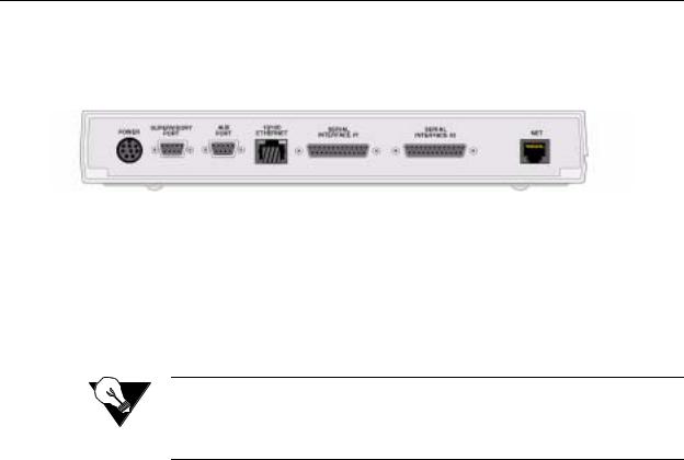
Rear Panel Connections
The rear panel of the WANsuite 5370 has seven connectors −
SUPERVISORY PORT, AUX PORT,10/100 ETHERNET, SERIAL INTERFACE #1, SERIAL INTERFACE #2, and NET − as shown in Figure 1.2 below.
Figure 1.2 WANsuite 5370 Rear Panel
Supervisory Port
The SUPERVISORY PORT is a DB-9 female DCE connector that supports a variety of configurable parameters, including port speed, character size, parity, and stop bits. The Supervisory port speed can be set to 1200, 2400, 4800, 9600, 19200, 38400, 57600, or 115200 bps. Default settings for the Supervisory port are 19200 bps, 8 bits, no parity, and 1 stop bit.
NOTICE: For information on pinout assignments for the DB-9 female DCE connector, refer to Supervisory and Auxiliary Port Pin Assignments on page A-8. See Ordering Information on page A-4 for information on cables for this connector.
The Supervisory port performs several different functions. It serves as the VT100 interface port, providing VT100 screens. It also supports asynchronous PPP, providing access to the Web Server interface. In addition, the Supervisory port is an asynchronous data port. Data is encapsulated in frame relay packets and then transmitted through the Network port.
A b o u t t h e W A N s u i t e 5 3 7 0 1-9

Upon power-up, the Supervisory port can send out diagnostic messages until the Supervisory service acquires the port. These diagnostic messages can disrupt the connected device; however, you can configure the unit to disable their transmission.
NOTICE: A null modem (crossover) cable is required to connect a modem to the
Supervisory port.
Auxiliary Port
The AUXILIARY PORT is also a DB-9 female DCE connector that supports the same configurable parameters as the Supervisory port with the addition of flow control. The Auxiliary port speeds are also the same as the Supervisory port’s and the defaults are the same. However, the Auxiliary port’s only function is to support asynchronous data transmission (i.e., SCADA).
10/100 Ethernet
The WANsuite 5370 provides one 10/100 ETHERNET interface for SNMP and Web browser access and for access to the IP Gateway feature. This interface is an eight-pin modular jack that complies with standard twisted-pair, 10/100Base-T requirements. The 10/100Base-T cable is supplied by the end user. Refer to Ethernet Connection Pin Assignments on page A-7 for pin assignments and cable descriptions.
Ethernet LED Indicators
There are two unlabeled indicator LEDs on either side of the 10/100 Ethernet jack. The LED on the left side of the jack pulses amber to indicate data activity (either transmit or receive). The LED on the right side of the jack lights green to indicate that the link layer is operational.
Serial Interfaces
The two SERIAL interfaces located on the rear of the WANsuite 5370 are multi-protocol interfaces presented physically as DB-25 connections. The protocols supported by these interfaces are RS-232, EIA-530, and V.35.
Optional cables that adapt the DB-25 interface to the 34-pin V.35 interface are available.Their part numbers are listed under Optional Equipment on page A-4. DB-25 to DB-25 cables are also available if your installation needs require them. See Ordering Information on page A-4 for details. Pin assignments for the Serial interface are listed in Appendix A, Specifications.
CAUTION: FCC rules require that interconnecting cables carrying high-speed data be shielded appropriately to minimize radio frequency interference.
1-10 |
W A N s u i t e 5 3 7 0 |

Network Interface
Labeled on the rear panel of the WANsuite 5370 as NET, the Network interface connection is a standard RJ-48C, eightpin modular jack that contains an automatic line build out (ALBO). The ALBO allows the unit to be located a substantial distance away from the telco network interface with a receive signal level to − 49 dB. The Network LBO level cannot be set by the user. To view the pinout assignments for this interface, refer to Network Interface Pin Assignments on page A-8.
CAUTION: In accordance with FCC Rules, Part 68.218(b), you must notify the telephone company prior to disconnecting this product.
Power Connection
The POWER port is an eight-pin circular mini-DIN connector that connects either an autoranging 100–240 VAC (shown in Figure 1.3 below) or an autoranging 18− 150 VDC external power supply (connection shown in below in Figure 1.4) to the unit. The WANsuite 5370 must be used with the UL Listed/CSA Certified Class 2 power supply provided with the unit or ordered separately from Verilink. The unit has no power switch.
NOTICE: Other power supply options are available. Refer to Power on page A-2.
Figure 1.3 WANsuite 5370 Power Supply Unit
A b o u t t h e W A N s u i t e 5 3 7 0 1-11
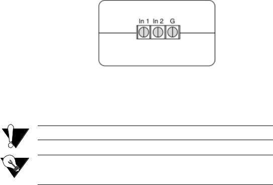
Figure 1.4 Connection for VDC Power Supply
When power is applied to the unit, the front panel indicators flash for approximately 10 to 15 seconds as the unit initializes. The green POWER LED on the front panel will remain illuminated as long as the unit receives power. This LED turns amber when the unit is in test mode.
CAUTION: Always plug the external power supply into a grounded power outlet.
NOTICE: Per UL 1950 and CSA 950 Clause 1.7.2, if the power supply cord is intended to serve as a disconnect device, an easily accessible socket must be installed near the equipment.
Power Failure
If the indicator does not illuminate, check the power connections and the primary AC circuit breaker.
The WANsuite 5370 provides non-volatile memory retention of the unit configuration in case of a power failure. This feature allows the unit to automatically restore normal service and retain pre-existing time and date information following a power loss.
1-12 |
W A N s u i t e 5 3 7 0 |

C H A P T E R
2
INSTALLATION
This chapter describes the contents of your WANsuite 5370 shipment and provides information on connecting and installing the unit.
The WANsuite 5370 uses an “Installation Wizard” to help you automatically install the unit quickly and accurately. Procedures for using this Installation Wizard are also described in this chapter.
Unpacking and Inspection
The WANsuite 5370 is shipped in cardboard cartons with foam inserts for shock and vibration protection. When your shipment arrives, inspect the shipping container and contents, and compare all items with those on the packing list.
If the contents of the shipment are incomplete or if there is mechanical damage or defect, notify Verilink Customer Service (page xii). If the shipping container or cushioning material is damaged, notify both the carrier and Verilink immediately and make a notation on the delivery receipt that the container was damaged. (If possible, obtain the signature and name of the person making delivery.) Retain the packaging material until the contents of the shipment have been checked for completeness and the unit has been checked both mechanically and electrically.
Supplied Materials
The WANsuite 5370 ships with the following standard items:
•External AC power supply and power cord) or external DC power supply
•
•
•
•
•
DDS network cable
Serial (Supervisory) cable
Adapter (DB-9M to DB-25F)
Cable (DB-9M to DB-25F)
Verilink documentation CD
I n s t a l l a t i o n 2-1
For specific applications, see Optional Equipment on page A-4 for additional cables and adapters. Contact Verilink Technical Support (page xii) for further assistance.
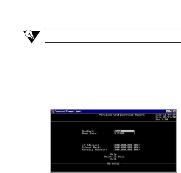
Installation Wizard
One of the ways to configure and monitor the WANsuite 5370 is through the Web Browser interface. To gain access to this interface, the unit must be configured with an IP Address. Verilink provides a DOS-based program – the Verilink Configuration Wizard – to aid in this initial configuration.
NOTICE: You may also access the Verilink Configuration Wizard on Verilink’s
Web site: www.verilink.com.
To configure the IP Address using the Verilink Configuration Wizard, perform the following steps:
1Using the supplied cable, connect the unit’s DB-9 Supervisory port to a COM port on your PC. (Take note of which COM port is connected.)
2Insert the Verilink CD-ROM disc (provided with the WANsuite 5370) into your PC’s CD-ROM drive.
3Use Windows “Explore” to view the contents of the CD and select the folder labeled “Utilities.” In this folder will be a file named ipwiz.exe; this executable file is the Verilink Configuration Wizard application. Double-click on this file to launch the program. After the program is fully launched, you will see the following screen:
4Using the Tab key to move from field to field, move the cursor to the “COM Port” field. Using the Spacebar, toggle between the available options until the correct COM port is shown (COM1, COM2, COM3, or COM4). Be sure to choose the same COM port as the port to which you connected the unit.
5By default, the “Baud Rate” field will display 115200 (bits per second). For the purpose of this installation, do not change the displayed baud rate from its default. Proceed directly to the next step.
2-2 |
W A N s u i t e 5 3 7 0 |
6Using the Tab key again, move the cursor to the “IP Address” field and enter the appropriate IP Address for the unit (xxx.xxx.xxx.xxx). If necessary, repeat this process for the “Subnet Mask” and “Gateway Address” fields.
7Next, move the cursor to the “Write To Unit” field and press the Enter key. The program will prompt you to reset the unit.
8To reset the unit, cycle the unit’s power (i.e., disconnect the power supply cable from the unit and then reconnect it). The Configuration Wizard will then automatically download the configuration information to the unit.
9Note the status messages displayed at the bottom of the Configuration Wizard screen. When the download is complete, your PC will beep and the status message bar will display “Finished.”
10Finally, move the cursor to the “Exit” prompt and press Enter. The Configuration Wizard program will close.
I n s t a l l a t i o n 2-3
2-4 |
W A N s u i t e 5 3 7 0 |
Loading...