


Digital Drive®
SMS™-1
Subwoofer
Management
System
U S E R ’ S
M A N U A L
F e a t u r i n g S o f t w a r e Ve r s i o n 2 . 1

Caution!
.w w w . v e l o d y n e . c o m |
Digital Drive User’s Manual |
i |

Attention!
.w w w . v e l o d y n e . c o m |
Digital Drive User’s Manual |
ii |

Vorsicht!
.w w w . v e l o d y n e . c o m |
Digital Drive User’s Manual |
iii |
Attenzione!
.w w w . v e l o d y n e . c o m |
Digital Drive User’s Manual |
iv |

Table of Contents |
|
Congratulations ................................................................................................... |
1 |
Before you Begin ................................................................................................. |
1 |
Package Contents................................................................................................ |
2 |
Product Features and Controls .............................................................................. |
2 |
- SMS-1 .......................................................................................................... |
2 |
- Remote Control .............................................................................................. |
3 |
- Digital Drive Accessory Kit ............................................................................... |
5 |
Installation Overview ............................................................................................. |
5 |
SMS-1 Controls and Ports ................................................................................. |
5 |
Installation – Quick Start ....................................................................................... |
8 |
Installation – Step-by-Step...................................................................................... |
9 |
- SMS-1 Cable Connections ................................................................................ |
9 |
- A Word About SMS-1 Outputs.......................................................................... |
9 |
- A Word About Interconnect Cables ................................................................. |
10 |
- A Word About Connecting more than one SMS-1.............................................. |
10 |
SMS-1 Setup - OVERVIEW................................................................................... |
12 |
- Quick Setup Using Self-EQ .............................................................................. |
12 |
- ON-SCREEN Setup ........................................................................................ |
12 |
Onscreen Programming and Setup – Step by Step.................................................. |
17 |
Restoring Defaults ............................................................................................. |
34 |
Runtime Mode .................................................................................................. |
35 |
About Room Equalization..................................................................................... |
38 |
Care of Your Digital Drive SMS-1.......................................................................... |
38 |
Troubleshooting and Service ................................................................................ |
38 |
Appendix A: RS-232 Serial Overview and Commands .............................................. |
39 |
Appendix B: Summary of Special Remote Codes..................................................... |
41 |
.w w w . v e l o d y n e . c o m |
Digital Drive User’s Manual |
v |

Congr atulations
Congratulations on your purchase of a Velodyne Digital Drive SMS-1 Subwoofer Management System! This system enables you to bring the power of Velodyne’s patent-pending Digital Drive bass management to any subwoofer. Digital Drive technology, universally acknowledged as the state-of-the-art in bass reproduction, is the result of years of research and development, combining advanced Digital Signal Processing (DSP), software, equalizer, and audio filter technologies. The result is a product that provides levels of bass management for non-DD subwoofers previously unattainable.
This exceptional product will provide you with years of unparalleled listening pleasure. Enjoy!
Before you begin
Please observe the following instructions to insure safe and proper system operation.
Warning!
To prevent fire or shock hazard, do not expose this equipment to rain or moisture. To avoid electrical shock, do not open the chassis cover. Please observe all warnings on the equipment itself. There are no user serviceable parts inside. Please refer all service questions to your authorized Velodyne dealer.
P r i o r to installation
Please unpack the system carefully! Remove all staples if used to seal the carton as they can scratch the chassis. Please save the carton and all packaging materials for future use. Packing this unit in any other carton may result in damage when shipping. Please take a moment to record the serial number and date/location of purchase in the space provided on the warranty card for future reference or register on-line at www.velodyne.com.
NOTE: Be sure to check the Velodyne website at www.velodyne.com for updates to the SMS-1 software and/or this manual.
Caution!
This SMS-1 has electronics built into the cabinet. Do not place the cabinet next to sources of heat such as furnace registers, radiators, etc. Do not place the unit near sources of excessive moisture, such as evaporative coolers, humidifiers, etc. The power cord should be routed in such a way that it will not be walked on, pinched, or compressed in any way that could result in damaging the insulation or wire.
.w w w . v e l o d y n e . c o m |
Digital Drive User’s Manual |
1 |

Pack age Contents
Your Velodyne Digital Drive SMS-1 consists of the following components:
•Digital Drive SMS-1
•Power Supply with Cord
•Remote control
•Digital Drive Accessory Kit
CAUTION: Many of the accessories are embedded in the included foam endcaps. Please do not discard.
Product Features and Controls
S M S - 1
Prominent features of your new Digital Drive SMS-1 include:
•Front panel display indicating volume, preset, and operating modes (auto-EQ, mute, night mode)
•Control for up to three subwoofers
•Balanced (XLR) input
•Line-level (RCA) inputs and thruputs
•Speaker-level inputs
•Fixed 80Hz high-pass crossover (RCA output)
•Variable volume control
•Detachable 6-foot power supply
•Included rack mount ears
•On-screen controls:
-Auto-EQ
-Graphic or Parametric Equalizer controls for room EQ
-Adjustable (15Hz – 199Hz) low-pass crossover (defeatable)
-Multiple staggered low-pass crossovers (6dB/octave, initial to 48dB/octave, ultimate)
-Adjustable (15Hz - 35Hz) subsonic filter (defeatable)
-Multiple staggered subsonic filters (12dB/octave, initial to 48dB/octave, ultimate)
-Variable volume control
-Adjustable phase control (0° - 180° in 15° increments)
-Selectable polarity (+/-)
-12 Volt trigger (defeatable)
-6 presets for customized listening modes and EQ defeat
-Selectable default preset
-Switchable LCD light
-Night Mode maximum volume setting
-Save settings indicator
-Daisy chain feature
.w w w . v e l o d y n e . c o m |
Digital Drive User’s Manual |
2 |

Remote Contr ol
The Velodyne Digital Drive infrared remote control allows you to set up, adjust, and reset your SMS-1 when connected to a television or a video monitor. You will also use your remote to activate preset listening values, set the SMS-1’s volume up or down, mute the SMS-1, or set a night operational mode.
Take care not to lose or misplace your remote control as adjustments to the SMS-1 (with the exception of volume control) can only be done using the remote.
NOTE: Two 1.5V AA batteries are required and included for operation of the remote control.
.w w w . v e l o d y n e . c o m |
Digital Drive User’s Manual |
3 |

Remote Contr ol Buttons
A brief description of each button on the remote control follows:
•PWR – Causes the SMS-1 to stand by.
•NUMERIC KEYPAD – Used to enter an unlock code to enter SETUP mode, and for other functions.
•SET (+/-) – Increases or decreases the Q value for a parametric EQ, or sets values on the SYSTEM SETTINGS page.
•LIGHT – Turns the SMS-1’s LCD light on or off.
•NIGHT – Limits the peak output of the SMS-1, and illuminates the NIGHT indicator on the LCD screen.
•VOL (+/-) – Raises or lowers the volume of your SMS-1 as indicated on the LCD display.
•MUTE – Mutes and unmutes the SMS-1.
•TEST – Used to toggle between the SYSTEM SETTINGS screen and the SYSTEM RESPONSE screen during setup.
•EXIT – To exit SETUP mode. The unit will ask if you want to save settings before exiting.
•SELECT - To toggle field values.
•RESET – Used to reset volume to the last saved setting on the main screen, and to defeat crossovers on the settings screen.
•MENU – Enters SETUP mode from the introductory screen.
•PRESETS – To access the five presets and one EQ defeat listening modes. Initially set at the factory, they are fully user adjustable. The
front panel LCD indicates which preset you have selected.
Figure 1: Velodyne Digital Drive remote control
.w w w . v e l o d y n e . c o m
Digital Drive User’s Manual |
4 |
Digital Drive Accessor y Kit
The Velodyne Digital Drive Accessory Kit contains the following six components:
•Calibrated precision microphone
•Microphone windscreen cover
•Tabletop microphone stand
•Microphone stand adapter
•6 foot audio cable
•6 foot video cable
•20-foot XLR microphone cable
Installation Overview
Your new Velodyne SMS-1 provides for a number of installation options. Read all the installation information below in order to determine which installation option is best for your system.
Remember to perform all installation procedures with SMS-1 unplugged until instructed to activate it!
SMS - 1 Contr ols and Por ts
The Velodyne Digital Drive SMS-1 is set up, configured, and adjusted by the controls, inputs, and connections located on the rear panel of the unit. Figure 1 shows the location of each of these important operational interfaces. Brief descriptions of each interface follow.
.w w w . v e l o d y n e . c o m |
Digital Drive User’s Manual |
5 |
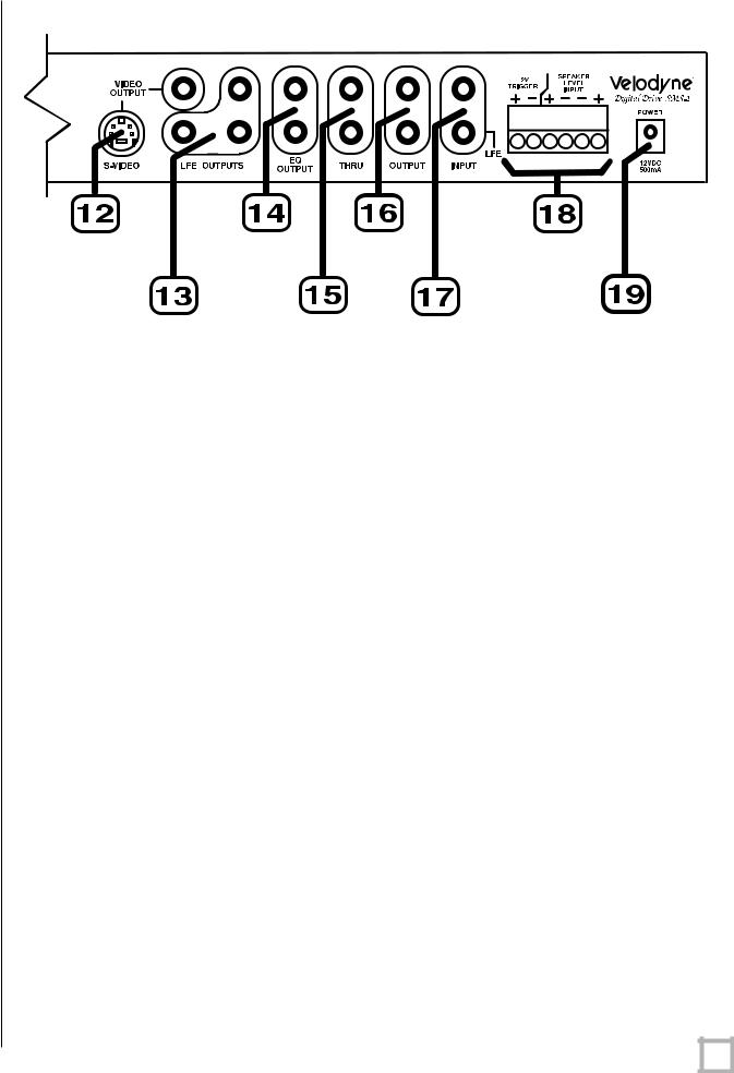
Figure 2: Digital Drive Front and Rear Panel Connections
(1)POWER – Press the POWER switch to the ON position to activate the SMS-1. If the unit is to be left unused for an extended period of time, press the switch to the OFF position to prolong the life of the SMS-1.
(2)IR Remote Sensor.
(3)LCD Display – This display shows subwoofer volume, preset, and indicates auto-EQ, self- EQ, mute, and night mode operation.
(4)MIC INPUT – This XLR input jack is for the XLR microphone cable.
(5)VOLUME UP/DOWN – Press the black UP pushbutton to incrementally raise your SMS-1’s system volume; press the black DOWN pushbutton to incrementally lower your SMS-1’s system volume. Note the use of these buttons during software updates.
(6)XLR OUTPUT – This balanced connector sends the conditioned subwoofer audio signal to your subwoofer.
(7) LFE INPUT – This XLR input jack receives the LFE signal from your receiver or processor.
(8)MIC INPUT – This XLR input jack is for the XLR microphone cable.
(9)IR REMOTE – This connection allows for hook-up of an IR signal from a repeater or other similar device.
.w w w . v e l o d y n e . c o m |
Digital Drive User’s Manual |
6 |

(10)RS-232 OUT – Use this port to communicate with a second “daisy-chained” Digital Drive SMS-1.
(11)RS-232 IN – Use this port to communicate with your computer (for software updates), a touch panel remote control, or another upstream Digital Drive SMS-1. See Appendix A for an explanation of the use of the serial port, available commands, and their formats.
(12)EQ Video Output – Used to display the video generated by the SMS-1. S-Video or composite connections are available. A composite video cable is included. NOTE: Only connect to a single video output at a time.
(13)LFE OUTPUT – These connectors send the conditioned subwoofer audio signal to up to three subwoofers.
(14)EQ OUTPUT LEFT/RIGHT – Connect the audio cable from your accessory kit to these jacks: white plug to LEFT, and red plug to RIGHT.
(15)THRU – These RCA connectors are for sharing the same signal that goes into your SMS-1 with a second “daisy-chained” SMS-1 or other device. Unaltered line-level signal comes out of the THRU jack.
(16)OUTPUT – These RCA connectors incorporate the use of an 80Hz 6 dB/octave slope high pass crossover.
(17)INPUT LFE – These RCA input jacks are for line-level connection.
(18)12V TRIGGER/SPEAKER LEVEL INPUT RIGHT/LEFT – If the 12 volt trigger mode is active, 12 volts is required across these pins for power to be activated. The speaker- level connector allows for connection with exposed speaker wire.
(19)12V DC POWER SUPPLY INPUT - Connect the power supply to this jack.
.w w w . v e l o d y n e . c o m |
Digital Drive User’s Manual |
7 |

Installation – Quick Start
To quickly set up and take advantage of the auto-EQ feature in your new Digital Drive SMS-1, perform the following steps:
1.Unpack the SMS-1 and connect the power cable.
2.Connect an LFE input cable from your receiver/processor to the input jack. For other hookup options, see step 2 on page 9.
3.Connect a high quality line level cable from one of the LFE out jacks to your subwoofer.
4.Disable your subwoofer’s crossover if possible, and set its volume to one-quarter up to one-half setting.
5.Power up the unit and ensure that it is receiving and processing signal from your receiver (i.e. your subwoofer is playing bass).
6.Connect the microphone (found in the accessory kit) to the XLR mic input jack on the front or rear panel of the SMS-1 and place the mic in your favorite listening position.
7.Press 3-2-1 on the remote.
8.The subwoofer should emit 25 “sweep” tones then restart and play normally. NOTE: If you have the video connected you will see the sweep screen with Self-EQ mode indicated. This screen will show the EQ adjustments as they happen.
9.Adjust the SMS-1’s volume and your subwoofer’s volume to taste.
10.Enjoy your room-equalized sub!
.w w w . v e l o d y n e . c o m |
Digital Drive User’s Manual |
8 |

Installation– Step-By-Step
To ensure a quick and flawless installation of your Velodyne Digital Drive SMS-1, follow these setup instructions.
SMS - 1 Cable Connections
Make all necessary cable connections between the applicable SMS-1 connector port and your particular home electronics equipment in the following order:
1.Insert the detachable power supply into the power interface port on the rear panel of your SMS-1. Plug the male end of the cord into a convenient wall outlet.
2.Provide signal to your SMS-1 through one or more of the following connections (refer to your receiver/processor owner’s manual for available inputs to the SMS-1):
a.LFE INPUT (RCA, the RED jack at location 17 on Figure 1) – This is the most common input cable connection. Make a connection between this input and the LFE output of your receiver or processor; OR
b.LFE INPUT (XLR, location 7 on Figure 1) – Make a connection between this input and the balanced LFE outputs of your receiver or processor; OR
c.INPUT, LEFT and RIGHT (location 17 on Figure 2)– Make a connection between these inputs and the stereo outputs of your receiver or processor; OR
d.SPEAKER-LEVEL INPUT (location 18 on Figure 2) - Make a connection between these inputs and the left and right speaker connections on your receiver or processor. Make this connection by inserting speaker wire into the correct terminals of the terminal block.
3.Establish the return line-level connection (optional). Connect to a pre-amplifier’s main outputs and return them to your amplifier inputs. When installed in this fashion, your satellite speakers will be crossed over at 80Hz, which removes the lower bass from your amplifier and speakers, enabling them to do a better job reproducing high frequencies. By utilizing this method, you will have a bi-amplified system, gaining improved power and headroom for your system.
NOTE: To bypass the 80Hz crossover described in step 3, use the THRU output jacks instead of the OUTPUT jacks.
A wor d about SMS - 1 outputs
The Velodyne SMS-1 is designed to operate using the full range audio signal for input when using the digital built-in crossover. Most processors/receivers have a “subwoofer out” or LFE jack that is internally filtered and designed to be used with a conventional amplifier and speaker. In some rare cases, combining both an external crossover and the one internal to the SMS-1 may result in low output and increased noise. In these installations you may need to bypass the internal crossover in either the processor or Velodyne SMS-1. In some installations, simply setting one crossover to a higher frequency (such as 120Hz) will restore maximum performance. To bypass the SMS-1’s internal crossover when the unit is being fed a low pass signal from another crossover, refer to the SETUP instructions at step 14, below.
Note: If not using an |
external |
crossover, |
you |
should |
use |
the |
built-in |
crossover |
for |
optimal performance. |
|
|
|
|
|
|
|
|
|
.w w w . v e l o d y n e . c o m |
|
|
|
|
Digital Drive User’s Manual |
9 |
|||
 Loading...