


PC Scopes PCS500
PCS100 / K8031
CHECK THE Pc-Lab2000T M GETTING STARTED GUIDE
FOR SOFTWARE INSTALLATION
Reference Manual

PCS500 / PCS100 / K8031
VELLEMAN Instruments is a division of VELLEMAN Components NV
Legen Heirweg 33
9890 Gavere
Belgium
Support & updates : http://www.Velleman.be
ãVelleman Instruments
HPCS500_UK2001– 1
2

PCS500 / PCS100 / K8031
FCC information for the USA
This equipment has been tested and found to comply with the limits for a Class B digital device, pursuant to Part 15 of the FCC Rules. These limits are designed to provide reasonable protection against harmful interference in a residential installation. This equipment generates, uses and can radiate radio frequency energy and, if not installed and used in accordance with the instructions, may cause harmful interference to radio communications. However, there is no guarantee that interference will not occur in a particular installation. If this equipment does cause harmful interference to radio or television reception, which can be determined by turning the equipment off and on, the user is encouraged to try to correct the interference by one or more of the following measures:
∙Reorient or relocate the receiving antenna.
∙Increase the separation between the equipment and receiver.
∙Connect the equipment into an outlet on a circuit different from that to which the receiver is connected.
∙Consult the dealer or an experienced radio/TV technician for help.
Important
This equipment was tested for FCC compliance under conditions that include the use of shielded test leads between it and the peripherals. It is important that you use shielded cables and connectors to reduce the possibility of causing Radio and Television interference.
Shielded probes, suitable for the PCS500 oscilloscope can be obtained from the authorized Velleman dealer.
If the user modifies the PCS500 oscilloscope or its connections in any way, and these modifications are not approved by Velleman, the FCC may withdraw the user’s right to operate the equipment.
The following booklet prepared by the Federal Communications Commission may be of help: “How to identify and Resolve Radio-TV Interference problems”. This booklet is available from the US Government Printing Office, Washington, DC20402 Stock No. 044-000-00345-4.
3

PCS500 / PCS100 / K8031
GENERAL
The PCS500 / PCS100 / K8031 are digital storage oscilloscopes, using a computer and its monitor to display waveforms. All standard oscilloscope functions are available in the Windows program supplied. Its operation is just like a normal oscilloscope with the difference that most operations can be done using the mouse. The markers for indicating voltage and frequency also provide considerable ease of use and can be operated without difficulty using the mouse. Apart from being used as an oscilloscope, the unit can also be used as a spectrum analyzer and as a transient signal recorder, for recording voltage variations or for comparing two voltages over a longer period (over more than a year!). Connection is through the computer's parallel port; the scopes are completely optically isolated from the computer port. Any waveform displayed on the screen can be stored for later use in documents or for comparison of waveforms. Together with the PCG10 function generator, a powerful Bode plotter can be made. In the PCS500 the oscilloscope and transient recorder have two completely separated channels.
PCS500 features
∙Inputs: 2 channels, 1 external trigger input
∙Input impedance: 1 Mohm / 30pF
∙Frequency response ±3dB: 0Hz to 50MHz
∙Maximum readout error: 2.5%
∙Low noise
∙Pre-trigger function
∙Maximum input voltage: 100V (AC + DC)
∙Input coupling: DC, AC and GND
∙Optically isolated from computer
∙Supply voltage: 9 - 10Vdc / 1000mA
∙Dimensions: 230x165x45mm (9x6.5x1.8”)
∙Weight: 490g (17oz)
PCS100 / K8031 features
∙1 channel input
∙Input impedance: 1 Mohm / 30pF
∙Frequency response ±3dB: 0 Hz to 12MHz
∙Maximum readout error: 2.5%
∙Slew rate 1div/10ns
∙Low noise
∙Maximum input voltage: 100V (AC + DC)
∙Input coupling: DC, AC, (GND only for PCS100)
∙Optically isolated from computer
∙Supply voltage: 9 - 10Vdc / 500mA
∙Dimensions: 230x165x45mm (9x6.5x1.8”)
∙Weight: 400g (14oz)
4

PCS500 / PCS100 / K8031
Minimum system requirements
∙IBM compatible PC
∙Windows 95, 98, ME, (Win2000 or NT possible)
∙SVGA display card (min. 800x600)
∙Mouse
∙Free printer port LPT1, LPT2 or LPT3
∙CD Rom player
Options
∙Insulated measurement probe x1 / x10: PROBE60S
∙Soft carry case: GIP
Technical data
PCS500 Oscilloscope
∙Time base: 20ns to 100ms per division
∙Trigger source: CH1, CH2, EXT or free run
∙Trigger level: adjustable in whole screen
∙Input sensitivity: 5mV (10mV for PCS100 / K8031) to 15V/division
∙Record length: 4096 samples / channel
∙Sampling frequency: Real time* 1.25 kHz to 50 MHz
∙Sampling frequency: Repetitive*: 1 GHz (Equivalent Sampling Rate)
PCS100 / K8031 Oscilloscopes
∙Time base: 0.1us to 100ms per division
∙Trigger source: CH1 or free run
∙Trigger level: adjustable per ½ division
∙Input sensitivity: 10mV to 3V per division
∙Record length: 4079 samples
∙Sampling frequency: Real time* 800Hz to 32MHz
PCS500 / PCS100 / K8031 general data
∙Trigger edge: rising or falling
∙Step markers for voltage, time and frequency
∙Interpolation: linear or smoothed
∙Vertical resolution: 8 bit
∙Auto setup function
∙True RMS readout (only AC component)
(*) Real-time Sampling:
A sampling mode in which the picture is build by collecting as many samples as it can as the signal occurs.
(*) Equivalent Sampling rate:
A sampling mode in which the picture is builds using repetitive signals by capturing information from each repetition.
5

PCS500 / PCS100 / K8031
Transient recorder
∙Timescale: 20ms/Div to 2000s/Div
∙Max record time: 9.4hour/screen
∙Automatic storage of data
∙Automatic recording for more than 1 year
∙Max. Number of samples: 100/s
∙Min. number of samples: 1 sample/20s
∙Markers for time and amplitude
∙Zoom function
∙Record and display of screens
∙Data format: ASCII
Spectrum analyser
∙Frequency range PCS500: 0.. 1.2kHz to 25MHz
∙Frequency range PCS100 / K8031: 0.. 400Hz to 16MHz
∙Linear or logarithmic timescale
∙Operating principle: FFT (Fast Fourier Transform)
∙FFT resolution: 2048 lines
∙FFT input channel: CH1 or CH2 (CH1 for PCS100 / K8031)
∙Zoom function
∙Markers for amplitude and frequency
6

PCS500 / PCS100 / K8031
SAFETY and WARNINGS
Symbols displayed on the unit
!
Important safety information, see user manual.
The PC scopes are optically isolated from the PC, but even then it is advisable to measure only safe devices.
ÞMeasurements should be avoided in case of polluted or very humid air. One should also refrain from measuring conductors or installations that use voltages that exceed 600Vrms above ground level. CAT II indicates conformity for measurements of domestic installations.
ÞThe maximum input voltage for the connections of the unit stands at 100Vp (AC+DC)
ÞDo NOT open the enclosure while performing measurements.
ÞRemove all test leads before opening the enclosure in order to avoid electrical shock.
ÞUse a measuring probe with an insulated connector ( e.g. type PROBE60S) when measuring voltages exceeding 30V.
Before making measurements and for safety reasons, it is important to know some information about the measured unit.
Safe devices are:
∙Battery operated equipment
∙Equipment supplied via a transformer or adapter.
Unsafe devices are:
∙Equipment directly connected to mains (e.g. old TV sets)
∙Equipment that contains components that are directly connected to mains (dimmers…).
It is advisable, when measuring on above equipment, to use a isolation transformer.
Always be careful when measuring directly to the mains; please remember that the ground of both channels is interconnected!
FIMPORTANT: Prior to measuring high voltages, set the probe to the X10 position.
7
PCS500 / PCS100 / K8031
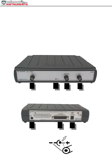
CONNECTIONS
Survey of the connections and controls
1.BNC input connectors (1CH for PCS100 / K8031)
2.BNC external trigger input (max. input 100Vp AC+DC) only PCS500 3.Power indication LED (software driven)
4.Adapter connection (observe the polarity!) 5.Parallel port connector
6.X10 probe testing signal (at front panel for PCS100 / K8031) PCS500 PICTURES
1 |
3 |
2 |
1 |
6 |
5 |
4 |
The unit is connected to the printer port LPT of the computer, using a parallel cable.
8
 Loading...