


 Loading...
Level and Pressure
Operating Instructions
VEGABAR 40 (HART®) 

 WE'VE GOT
ABILITY
OPERATE
t i ZERO
SPAN
1 |
2 |
3 |
5 |
6 |
7 |
8 |
+ |
- |
- |
|
4...20mA |
VEGADIS 10 |
AM10 |
|
+ |
|
||
E12
OK
1 |
2 |
3 |
5 |
6 |
7 |
8 |
+ |
- |
- |
|
4...20mA |
VEGADIS 10 |
AM10 |
|
+ |
|
||
E12
p

Contents
Contents
|
Safety information ........................................................................ |
2 |
|
|
Note Ex area ................................................................................ |
2 |
|
1 |
Product description |
|
|
|
1.1 |
Function and configuration .................................................. |
4 |
|
1.2 |
Self-monitoring ..................................................................... |
4 |
|
1.3 |
Technical data ....................................................................... |
5 |
|
1.4 |
Approvals and certificates .................................................. |
9 |
|
1.5 |
Dimensions ......................................................................... |
10 |
2 |
Mounting |
|
|
|
2.1 |
Mounting instructions ......................................................... |
12 |
|
2.2 |
Compensation of the atmospheric pressure ................... |
12 |
3 |
Electrical connection |
|
|
|
3.1 |
Connection instructions ..................................................... |
12 |
|
3.2 |
Connection diagram .......................................................... |
13 |
|
3.3 |
Connection examples ........................................................ |
14 |
Safety information
Please read this manual carefully, and also take note of country-specific installation standards (e.g. the VDE regulations in Germany) as well as all prevailing safety regulations and accident prevention rules.
For safety and warranty reasons, any internal work on the instruments, apart from that involved in normal installation and electrical connection, must be carried out only by qualified VEGA personnel.
 Note Ex area
Please note the attached safety instructions containing important information on installation and operation in Ex areas.
These safety instructions are part of the operating instructions and come with the Ex approved instruments.
2 |
VEGABAR 40 (HART®) |

Contents
4 Setup |
|
|
4.1 |
Indicating module ............................................................... |
15 |
4.2 |
Setup with module |
|
|
"Adjustment of the basic functions“ .................................. |
15 |
4.3 |
Setup with module |
|
|
"Menu-driven adjustment with additional functions“ ........ |
17 |
4.4 |
Setup with adjustment software |
|
|
VEGA Visual Operating (VVO) ......................................... |
22 |
4.5 |
Setup with HART® handheld ............................................. |
30 |
5 |
Diagnostics |
|
|
|
5.1 |
Maintenance ....................................................................... |
36 |
|
5.2 |
Failure rectification ............................................................. |
36 |
6 |
Instrument modification |
|
|
|
6.1 |
Exchange of adjustment modules .................................... |
38 |
|
6.2 |
Exchange of electronics .................................................... |
39 |
|
6.3 |
Exchange of the process fitting ........................................ |
39 |
VEGABAR 40 (HART®) |
3 |

Product description
1 Product description
1.1 Function and configuration |
1.2 Self-monitoring |
VEGABAR 40 process pressure transmitters are efficient instruments for process pressure measurement. As pressure sensor element, the dry ceramic-capacitive measuring cell CERTEC® is used. The process pressure causes a capacitance change within the measuring cell via the diaphragm. This capacitance change is detected by an ASIC (Application specific integrated circuit) and converted into a pressure proportional signal by the integrated sensor electronics with microcontroller. Precise, high-resolution digital processing of measured data ensures excellent technical data.
The electronics module is powered by a separate VEGA signal conditioning instrument, a stabilised power supply unit or a PLC (active input). After the adjustment, a standardised 4 … 20 mA current signal is made available which can be displayed (e.g. in PLC systems) or further processed.
For carrying out adjustment, the following alternatives are available:
-adjustment module directly on VEGABAR
-adjustment module in external housing (VEGADIS 10)
-via PC with adjustment software VEGA Visual Operating (VVO)
-with HART® handheld
To improve reliability, the functionality of important electronic components is constantly checked, and internal parameters such as sensor value, temperature and operating voltage are closely monitored.
VEGABAR 40 with ceramic CERTEC® measuring cell offers the advantage of continuous self-monitoring. The measuring and reference capacitances of the measuring cell have a predefined correlation to each other over the entire measuring range. Any deviation from these data is a reliable indicator of a malfunction of the measuring cell.
If errors or malfunctions are detected during these routines, the fault signal is triggered via the 4 … 20 mA output (current jump to
3,6 mA or 22 mA).
4 |
VEGABAR 40 (HART®) |

Product description
1.3 Technical data
Mechanical data
Materials, wetted parts
Process connection |
brass 2.041, stainless steel 1.4571 |
||
Diaphragm |
saphire-ceramic® (99.9 % Oxide ceramic) |
||
Seal, measuring cell |
Viton, EPDM, Hifluour, Kalrez |
||
Materials, non wetted parts |
|
|
|
Housing |
high resistance plastic PBT (Polyester) |
||
- |
optional |
Alu-die casting, powder-coated |
|
Ground terminal |
stainless steel 1.4305 |
||
Indicating module window |
Lexan |
||
Weight |
|
|
|
VEGABAR |
approx. 0,8 kg |
||
Adjustment and indicating elements |
|
|
|
Adjustment of the basic functions |
2 keys, 1 rotary-type switch |
||
Menu-driven adjustment with |
|
|
|
additional functions |
|
|
|
- |
adjustment elements |
4 keys |
|
- |
indicating elements |
DOT-matrix display, 3 lines with 7 figures each |
|
Indicating module |
LC display with |
||
|
|
- |
bar graph (20 segments) |
|
|
- |
digital value (4 digits) |
|
|
- |
tendency indicators for rising or falling values |
VEGABAR 40 (HART®) |
5 |

|
|
|
Product description |
|
|
|
|
|
|
|
|
Gauge pressure |
Low pressure |
|
Nominal measuring range |
resistance |
resistance |
||
Gauge pressure |
|
|
|
|
0…0,1 bar / 0…10 kPa |
15 bar / 1 500 kPa |
-0,2 bar / -20 kPa |
||
0…0,2 bar / 0…20 kPa |
20 bar / 2 000 kPa |
-0,4 bar / -40 kPa |
||
0…0,4 bar / 0…40 kPa |
30 bar / 3 000 kPa |
-0,8 bar / -80 kPa |
||
0…1,0 bar / 0…100 kPa |
35 bar / 3 500 kPa |
-1,0 bar / -100 kPa |
||
0…2,5 bar / 0…250 kPa |
50 bar / 5 000 kPa |
-1,0 bar / -100 kPa |
||
0…5,0 bar / 0…500 kPa |
65 bar / 6 500 kPa |
-1,0 bar / -100 kPa |
||
0…10,0 bar / 0…1 000 kPa |
90 bar / 9 000 kPa |
-1,0 bar / -100 kPa |
||
0…20,0 bar / 0…2 000 kPa |
130 bar / 13 000 kPa |
-1,0 bar / -100 kPa |
||
0…40,0 bar / 0…4 000 kPa |
200 bar / 20 000 kPa |
-1,0 bar / -100 kPa |
||
0…60,0 bar / 0…6 000 kPa |
200 bar / 20 000 kPa |
-1,0 bar / -100 kPa |
||
-0,05…+0,05 bar / -5…+5 kPa |
15 bar / 1 500 kPa |
-0,2 bar / -20 kPa |
||
-0,1…+0,1 bar / -10…+10 kPa |
20 bar / 2 000 kPa |
-0,4 bar / -40 kPa |
||
-0,2…+0,2 bar / -20…+20 kPa |
30 bar / 3 000 kPa |
-0,8 bar / -80 kPa |
||
-0,5…+0,5 bar / -50…+50 kPa |
35 bar / 3 500 kPa |
-1,0 bar / -100 kPa |
||
-1,0…0,0 bar / -100…0 kPa |
35 bar / 3 500 kPa |
-1,0 bar / -100 kPa |
||
-1,0…+1,5 bar / -100…+150 kPa |
50 bar /5 000 kPa |
-1,0 bar / -100 kPa |
||
-1,0…+4,0 bar / -100…+400 kPa |
65 bar / 6 500 kPa |
-1,0 bar / -100 kPa |
||
-1,0…+10,0 bar / -100…+1 000 kPa |
90 bar / 9 000 kPa |
-1,0 bar / -100 kPa |
||
-1,0…+20,0 bar / -100…+2 000 kPa |
130 bar / 13 000 kPa |
-1,0 bar / -100 kPa |
||
-1,0 …+40,0 bar / -100…+4 000 kPa |
200 bar / 20 000 kPa |
-1,0 bar / -100 kPa |
||
-1,0…+60,0 bar / -100…+6 000 kPa |
200 bar / 20 000 kPa |
-1,0 bar / -100 kPa |
||
Absolute pressure |
|
|
|
|
0…1,0 bar / 0…100 kPa |
35 bar / 3 500 kPa |
|
|
|
0…2,5 bar / 0…250 kPa |
50 bar / 5 000 kPa |
|
|
|
0…5,0 bar / 0 …500 kPa |
65 bar / 6 500 kPa |
|
|
|
0…10,0 bar / 0…1 000 kPa |
90 bar / 9 000 kPa |
|
|
|
0…20,0 bar / 0…2 000 kPa |
130 bar / 13 000 kPa |
|
|
|
0…40,0 bar / 0…4 000 kPa |
200 bar / 20 000 kPa |
|
|
|
0…60,0 bar / 0…6 000 kPa |
200 bar / 20 000 kPa |
|
|
|
6 |
VEGABAR 40 (HART®) |
Product description
Electrical data
Adjustment ranges
Zero |
adjustable from -20 … +95 % of nominal range |
|||
Span |
adjustable from 3,3 … 120 % of nominal range |
|||
Supply and signal circuit |
|
|
|
|
Supply voltage |
12 … 36 V DC |
|||
Exd version (pressure-tight encapsulation) |
18 … 36 V DC |
|||
Permissible residual ripple |
USS |
≤ |
1 V |
|
- |
at 500 Hz … 10 kHz |
USS |
≤ |
10 mV |
Output signal |
|
|
|
|
- |
range |
3.8 … 20.5 mA |
||
- |
resolution |
6 µA |
|
|
Current limiting |
approx. 22 mA |
|||
Fault signal |
22 mA (3.6 mA) |
|||
Integration time |
0 … 10 s adjustable |
|||
Rise time |
85 ms (ti = 0 sec; 0 – 63 %) |
|||
Connection cable |
2-wire |
|||
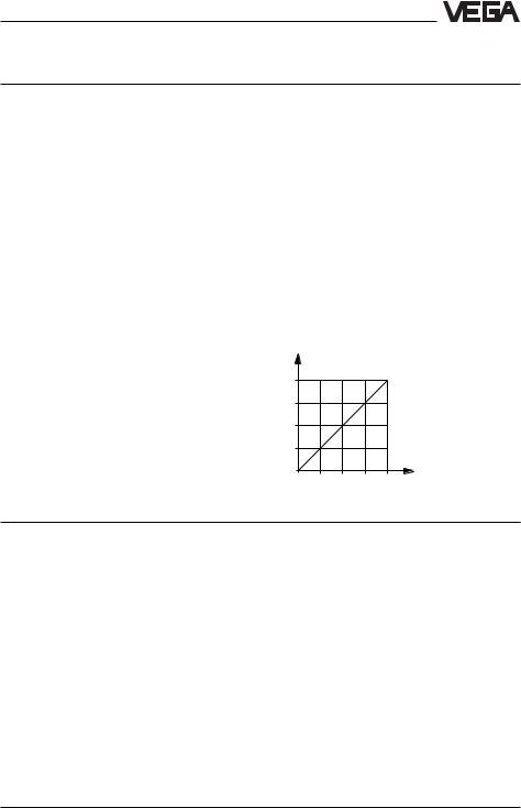
Max. permissible load |
dependent on the supply voltage |
|||
|
|
(see load diagram) |
||
Ohm |
1000 |
|
|
|
|
750 |
|
|
|
|
|
in |
|
|
|
|
|
|
|
|
|
|
|
Ltotal |
500 |
|
|
|
|
R |
|
|
|
|
|
Load |
250 |
|
|
|
|
|
0 |
|
|
|
|
|
12 |
18 |
24 |
30 |
36 |
Voltage of the external energy UH in Volts
Display and adjustment circuit
For connection to |
VEGADIS 10 and/or indicating module |
Data transmission |
digital |
Connection cable |
4-wire (standard cable) |
Max. cable length |
25 m |
Connection |
|
Cable entry |
M20 x 1.5 (for cable-ø 5 … 10 mm) |
Screw terminals |
for conductor cross sections of up to 2.5 mm2 |
Protective measures |
|
Protection 1) |
IP 65 |
Protection class |
III |
Overvoltage category |
III |
1)Use of a suitable seal for the cable in the PG is necessary for maintaining the housing protection. If the seal used does not fit the cable, it should be replaced by a suitable one.
VEGABAR 40 (HART®) |
7 |

Product description
Accuracy (similar to DIN 16 086, DIN V 19 259 - 1 and IEC 770)
Deviation
Reference conditions (acc. to IEC 770) |
|
|
- |
temperature |
15°C … 35°C |
- |
rel. humidity |
45 % … 75 % |
- |
air pressure |
860 mbar … 1060 mbar/86 kPa … 106 kPa |
Determination of characteristics |
limit point adjustment acc. to DIN 16 086 |
|
Characteristics |
linear |
|
Deviation in characteristics |
incl. hysteresis and repeatability |
|
- |
Turn Down 1 : 1 |
< 0.25 % with accuracy class 0.25 |
|
|
< 0.1 % with accuracy class 0.1 |
- |
Turn Down up to 1 : 5 |
typ. < 0.3 % with accuracy class 0.25 |
|
|
typ. < 0.1 % with accuracy class 0.1 |
- |
Turn Down up to 1 : 10 |
typ. < 0.4 % with accuracy class 0.25 |
|
|
typ. < 0.2 % with accuracy class 0.1 |
Influence of the ambient temperature |
|
|
Average temperature coefficient |
|
|
of the zero signal 2) |
|
|
- |
Turn Down 1 : 1 |
< 0.15 %/10 K with accuracy class 0.25 |
|
|
< 0.05 %/10 K with accuracy class 0.1 |
- |
Turn Down up to 1 : 5 |
typ. < 0.225 %/10 K with accuracy class 0.25 |
|
|
typ. < 0.075 %/10 K with accuracy class 0.1 |
- |
Turn Down up to 1 : 10 |
typ. < 0.3 %/10 K with accuracy class 0.25 |
|
|
typ. < 0.1 %/10 K with accuracy class 0.1 |
Long-term stability |
|
|
Long-term drift of the zero signal 1) 3) |
< 0.1 % per 2 years |
|
Other actuating variables |
|
|
Calibration position |
upright, diaphragm points downwards |
|
Influence of the mounting position |
< 0.2 mbar/20 Pa |
|
Vibration resistance |
mechanical vibrations with 4 g and |
|
|
|
5 … 100 Hz, tested acc. to the regulations of |
|
|
German Lloyd GL-characteristics 2 |
1)Relating to the nominal measuring range.
2)In the compensated temperature range of 0°C … +80°C, reference temperature 20°C.
3)Acc. to IEC 770, point 6.1.2 relating to the nominal measuring range.
8 |
VEGABAR 40 (HART®) |
Product description
Operating conditions
Ambient conditions
Ambient temperature |
-40°C … +85°C |
|
- |
with indicating module |
-20°C … +70°C |
Storage and transport temperature |
-40°C … +85°C |
|
Product temperature, dependent on the |
|
|
seal material of the measuring cell |
|
|
- |
Viton |
-20°C … +100°C |
- |
EPDM |
-40°C … +100°C |
- |
Hifluour |
-10°C … +100°C |
- |
Kalrez |
0°C … +100°C |
1.4 Approvals and certificates
Approvals
-Ex Zone 2
-StEx Zone 10
-Ship approval
-CENELEC EEx ia IIC
-ATEX II 1G EEx ia IIC
-ATEX II 2G EExd ia IIC
If the use of approved instruments is required for certain applications, the respective official documents (test reports, test certificates and conformity certificates) must be observed. These are supplied with the respective instrument.
CE conformity
VEGABAR 40 corresponds to the requirements of EMC (89/336/EWG) and NSR (73/23/EWG). Conformity has been judged acc. to the following standards:
EMC |
Emission |
EN 50 081 - 1: 1992 |
|
Susceptibility |
EN 50 082 - 2: 1995 |
NSR |
|
EN 61 010 - 1: 1993 |
NAMUR regulations
Full compliance with the NAMUR regulations NE 21 and NE 43.
VEGABAR 40 (HART®) |
9 |

Product description
1.5 Dimensions
Housing |
without indicating module |
|
with indicating module |
|
85 |
|
|
|
~76 |
|
|
|
|
|
Version |
|
|
|
plastic PBT |
|
72 |
82 |
|
|
Pg 13,5 |
|
|
|
Ground connection |
~76 |
|
|
90 |
|
|
|
|
|
Version |
|
|
|
Alu-die casting |
|
82 |
|
|
|
|
|
M20x1,5 |
|
Ground connection |
90 |
|
|
|
|
|
|
156 |
|
~76 |
|
|
|
Version |
|
|
|
Alu-die casting |
|
|
|
in EExd |
78 |
|
82 |
½" NPT |
|
|
|
|
|
Ground connection |
|
|
10 |
VEGABAR 40 (HART®) |
Product description
Process fittings
|
92 |
|
|
|
92 |
|
|
92 |
|
|
|
SW 27 |
|
|
|
SW 27 |
|
|
SW 27 |
|
|
|
25 |
|
15 |
20 |
25 |
|
20 |
25 |
5 |
|
|
|
¼" NPT |
|
|
|
ø11,4 |
|
|
ø3 |
|
|
|
½" NPT |
|
|
|
½" NPT |
|
|
ø6 |
|
|
|
|
|
|
|
|
M20x1,5 |
|
||
|
|
|
|
|
|
|
|
|
|
|
|
|
GN |
|
|
|
GA |
|
|
GB |
|
92 |
|
87 |
|
|
|
87 |
|
|
92 |
|
SW 27 |
|
SW 27 |
|
|
SW 27 |
|
SW 27 |
|||
25 |
5 |
20 |
3 |
|
|
20 |
3 |
|
25 |
5 |
|
ø3 |
|
|
|
G ¼ |
|
|
ø11,4 |
|
ø3 |
|
|
|
|
|
|
|
|
|
||
|
ø6 |
|
|
|
ø17,5 |
|
|
ø17,5 |
|
ø6 |
|
G ½ A |
|
|
|
G ½ A |
|
|
G ½ A |
|
G ½ A |
|
GM/GV |
|
|
|
GP |
|
|
GR |
|
GI |
VEGABAR 40 (HART®) |
11 |
|
|
Mounting, Electrical connection |
2 Mounting |
3 Electrical connection |
|
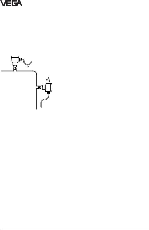
2.1 Mounting instructions |
3.1 Connection instructions |
|
VEGABAR can be mounted in any position. Cable entries must point downwards to avoid moisture ingress. For this purpose, the housing can be rotated by 330° in relation to the mounting part.
A seal, appropriate for connection, must be used for mounting. This seal is either supplied with VEGABAR or must be provided by the customer.
2.2Compensation of the atmospheric pressure
On instruments for gauge pressure measurement, the atmospheric pressure is compensated via a breather facility integrated in the housing.
The electronics in VEGABAR 40 requires a supply voltage of 12 … 36 V DC. It is provided in two-wire technology, i.e. supply voltage and current signal are led to the terminals via the same two-wire connection cable.
This external energy is provided via a separate power supply unit:
-power supply unit, e.g. VEGASTAB 690
-processing unit with integrated DC current source (e.g. active PLC input)
-VEGAMET or VEGADIS 371
Make sure that the external energy source is reliably separated from the mains circuits acc. to DIN VDE 0106, part 101. The above mentioned VEGA instruments meet this requirement, and protection class II is therefore ensured.
The external energy source must supply a terminal voltage of at least 12 V to the transmitter. The actual terminal voltage on the transmitter depends on the following factors:
-output voltage of the external energy source under nominal load.
-electrical resistances of the connected instruments in the circuit (see Connected instruments, load resistor).
12 |
VEGABAR 40 (HART®) |
Loading...