


 Loading...
Supplementary instructions
RS232/Ethernet connection
VEGAMET 391/624/625, VEGASCAN 693,
PLICSRADIO C62
Internet
PLC/SPS
Document ID: 30325

Contents
Contents
1 Product description |
4 |
|
1.1 |
Configuration.................................................................................................................... |
|
1.2 |
Principle of operation........................................................................................................ |
4 |
1.3 |
Adjustment........................................................................................................................ |
4 |
2 Connection |
5 |
|
2.1 |
Connection requirements.................................................................................................. |
|
2.2 |
Connection to PC/network/modem................................................................................... |
5 |
3Network settings
4Adjustment with PACTware
|
4.1 |
Start PACTware................................................................................................................. |
8 |
|
|
4.2 |
Create a project................................................................................................................ |
8 |
|
|
4.3 |
Project examples.............................................................................................................. |
9 |
|
5 |
Application examples |
12 |
||
|
5.1 |
Possible application areas.............................................................................................. |
||
|
5.2 |
Inventory enquiry via network and browser..................................................................... |
12 |
|
|
5.3 |
Inventory enquiry/VMI viaWEB-VV................................................................................. |
13 |
|
6 |
PC/DCS values |
15 |
||
|
6.1 |
General information........................................................................................................ |
||
7 |
Measured value enquiry via Web browser/http |
16 |
||
|
7.1 |
General information........................................................................................................ |
||
|
7.2 |
Access protection........................................................................................................... |
16 |
|
|
7.3 |
Measured value enquiry via web browser/Ethernet......................................................... |
16 |
|
|
7.4 |
Measured value enquiry via web browser/RS232........................................................... |
17 |
|
|
7.5 |
Measured value enquiry via http software....................................................................... |
19 |
|
8 |
Measured value transmission via e-mail |
21 |
||
|
8.1 |
General information........................................................................................................ |
||
|
8.2 |
E-mail transmission via network and mail server............................................................. |
22 |
|
|
8.3 |
E-mail transmission via modem/Dial-up.......................................................................... |
23 |
|
9 |
Measured value transmission to a WEB-VV server |
27 |
||
|
9.1 |
Prerequisites................................................................................................................... |
||
|
9.2 |
Signal conditioning instrument (RS232) with analogue/GSM/GPRS modem.................. |
27 |
|
|
9.3 |
Signal conditioning instrument (Ethernet) with MoRoS................................................... |
32 |
|
|
9.4 |
Signal conditioning instrument (Ethernet) in LAN............................................................ |
36 |
|
|
9.5 |
Setup MoRoS................................................................................................................. |
38 |
|
|
9.6 |
Set up measured value transmission.............................................................................. |
43 |
|
10 |
Measured value/Status files |
45 |
||
|
10.1 |
Description of the measurement data files...................................................................... |
||
|
10.2 |
Description of the status files.......................................................................................... |
48 |
|
11 |
Measured value transmission via SMS |
57 |
||
|
11.1 |
General information........................................................................................................ |
||
|
11.2 |
Settings for SMS transmission........................................................................................ |
57 |
|
12 |
Device trend/Data logger (only VEGAMET/VEGASCAN) |
|
|
|
|
|
|
||
2 |
RS232/Ethernet connection • VEGAMET 391/624/625, VEGASCAN 693, PLICSRADIO C62 |
|||
130701-EN-30325

|
|
Contents |
12.1 |
General information........................................................................................................ |
59 |
12.2 |
Setting of the device trend.............................................................................................. |
59 |
12.3 |
Start of the recording...................................................................................................... |
60 |
12.4 |
Load recording from device............................................................................................. |
60 |
30325-EN-130701
RS232/Ethernet connection • VEGAMET 391/624/625, VEGASCAN 693, PLICSRADIO C62 |
3 |

1 Product description
1 Product description
1.1Configuration
Each instrument can be optionally equipped with an RS232 or an Ethernet interface.These interfaces are permanently integrated and cannot be retrofitted or exchanged.Connection is carried out via an RJ-45 plug on the lower side of the respective instrument.
|
1.2 Principle of operation |
Application area |
RS232 interface |
|
The RS232 interface is particularly suitable for easy modem connec- |
|
tion for remote enquiry of measured values.For this purpose, external |
|
analogue, ISDN and GSM modems can be used. |
|
Ethernet interface |
|
With the Ethernet interface, instruments can be connected directly to |
|
an existing PC network.Each instrument is assigned its own IP ad- |
|
dress at which it can be accessed from anywhere in the network. |
1.3 Adjustment
To adjust the instrument, the configuration software PACTware and a suitable instrument driver (DTM) according to FDT standard are required.In addition, the DTMs can be integrated in other frame applications according to FDT standard.As an alternative, adjustment of the basic functions is possible via the integrated indicating and adjustment module.
All device DTMs fromVEGA are available as a free-of-charge standard version and as a full version that must be purchased.In the standard version, all functions for complete setup are already included.An assistent for simple project configuration simplifies the adjustment considerably.Saving/printing the project as well as import/ export functions are also part of the standard version.
In the full version there is also an extended print function for complete project documentation as well as a save function for measured value and echo curves.In addition, there is a tank calculation program as well as a multiviewer for display and analysis of the saved measured value and echo curves.
The standard version is available as a free-of-charge download under http://www.vega.com.The full version is available on CD from the agency serving you.
The licence regulations allow you to copy aVEGA DTM any number of times and use it on any number of computers, as long as you are using the standard version.The full version must be bought separately per computer and installation.
4 RS232/Ethernet connection • VEGAMET 391/624/625, VEGASCAN 693, PLICSRADIO C62
130701-EN-30325

2 Connection
2 Connection
2.1Connection requirements
First of all, the connection to power supply and sensor must be carried out as described in the respective operating instructions manual.
2.2Connection to PC/network/modem
Depending on the application, the connection is made via the optional RS232 or Ethernet interface.Alternatively, the built-in I²C or USB interface can be used for parameter adjustment depending on the instrument type.Details about the interface connection can be found in the respective operating instructions of the instrument.
30325-EN-130701
RS232/Ethernet connection • VEGAMET 391/624/625, VEGASCAN 693, PLICSRADIO C62 |
5 |

3 Network settings
3 Network settings
Dynamic IP-address (DHCP)
For instruments with integrated Ethernet interface, the automatic addressing via DHCP is preset, i.e.the IP address must be assigned by a DHCP server.Generally the instrument is contacted via the Host name.As an alternative, it is also possible to enter a static IP addr. with Subnet mask and optional Gateway addr.
Note:
The setting/modification of these network parameters will be only taken over, i.e.become effective, after a restart (interruption of power supply and restart).
Enquire of your responsible network administrator the type of addressing wished in your network and, if necessary, further specifications.The following adjustment options and parameters are available:
In this mode, all necessary parameters are assigned automatically to the signal conditioning instrument by a DHCP server available in the network.These parameters, e.g.the IP address, are thus not known to the user.What is more, they can change whenever the power supply is interrupted.That is why a host name must also be used, via which the instrument can be addressed in the network.Further parameters such as subnet mask, gateway or DNS server address do not have to be entered with automatic addressing.Every instrument is set to DHCP at the factory.
Static (fixed) IP address If no DHCP server is available (e.g.when connecting directly to a PC via cross-over cable) or automatic addressing is not wanted, the IP addresses are entered manually in each instrument.Your responsible network administrator provides a corresponding IP address with suitable subnet mask.
Subnet mask |
The subnet mask together with the IP-address determines which |
|
network segment the instrument should belong to. |
Standard gateway |
A gateway connects individual network segments – data traffic can |
|
thus be forwarded to destinations outside the local network segment. |
|
Entry of a gateway address is only required when manually assigning |
|
an address and for large networks. |
Host name |
With automatic addressing via DHCP, it is necessary to assign a host |
|
name because the IP address is generally not known or can change. |
|
By default, the host name consists of the serial number plus "VEGA-" |
|
in front.Anything can be entered as a host name, for example the |
|
name of the measurement loop or the plant.The host name must only |
|
include letters and numbers without spaces.Only the hyphen "-" is al- |
|
lowed as a special character.The first character must be a letter.The |
|
host name can have a maximum of 16 characters. |
DNS server |
The DNS server is responsible for assigning the IP address and the |
|
host name.This is particularly important with automatic addressing |
|
because network devices are accessed via the host name.Entry |
|
of a DNS server address is only required with manual addressing |
6 RS232/Ethernet connection • VEGAMET 391/624/625, VEGASCAN 693, PLICSRADIO C62
130701-EN-30325

3 Network settings
and large networks.Manual entry of a DNS server address is only possible via DTM – it cannot be done via the integrated display and adjustment unit.
Information:
A detailled description of these network parameters is available in the online help of the corresponding DTM.
30325-EN-130701
RS232/Ethernet connection • VEGAMET 391/624/625, VEGASCAN 693, PLICSRADIO C62 |
7 |

4 Adjustment with PACTware
4 Adjustment with PACTware
Create a project automatically
4.1Start PACTware
Start PACTware via theWindows start menu.In the standard setting, it is not necessary to enter a user name and a password.If user name/ password is requested, you can assign various users with different rights and assign a password under the PACTware menu item "Extras - User administration".
Information:
To ensure that all instrument functions are supported, you should always use the latest DTM Collection.Furthermore, not all of the described functions are always included in older firmware versions.For many instruments, the latest instrument software can be downloaded from our homepage.The transfer of the instrument software is carried out via PACTware.A description of the update procedure is also available in the Internet.
4.2Create a project
Starting point for the adjustment of all types of field devices is the partial or complete imaging of the device network in a PACTware project. This device network can be created automatically or manually and is displayed in the project window.
With simple device structures
For simple device structures, for example, a direct connection of the PC via aVEGACONNECT 4 with aVEGA sensor, it is not necessary to create the device network, but as an alternative you can directly click the desktop link "VEGA-USB-Scan".If PACTware is opened via this link, the connected sensor is automatically identified and the suitable DTM appears in the PACTware window in online mode.All PACTware adjustment elements are faded out so that only the information of the DTM relevant for the actual parameter adjustment are visible.
With complex device structures
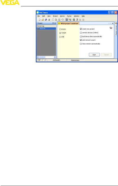
With complex device structures, the connection is carried out via the VEGA project assistant.TheVEGA project assistant is a manufactur- er-specific extension module for PACTware.It is part of eachVEGA DTM installation package and is installed automatically.By means of theVEGA project assistant, the connected instruments are identified automatically and integrated into the PACTware project.For this, only an online connection to the respective instruments is necessary.
TheVEGA project assistant is opened from the PACTware menu bar under "Project - VEGA project assistant".The window "VEGA project assistant" opens and you only have to select the requested interface for automatic generation of the project.If only one instrument is connected to the selected interface, the DTM parameter adjustment window will be opened automatically and the device data loaded.
You can find further information on how to use theVEGA project assistant in the corresponding online help.The online help can be opened directly from the window "VEGA project assistant".
8 RS232/Ethernet connection • VEGAMET 391/624/625, VEGASCAN 693, PLICSRADIO C62
130701-EN-30325
4 Adjustment with PACTware
30325-EN-130701
Fig. 1: Project assistant
Create a project manually Even when instruments that are to be parameterised are not yet available or connected, the project can be created manually (offline operation).All DTMs installed on the PC are displayed in the device catalogue.The DTMs usually have the same names as the instruments that can be adjusted with them.For a better overview, the device catalogue is divided into different subgroups.On the upper level, the manufacturers of the respective DTMs appear first.Below, the DTMs are divided into different function categories such as "Driver", "Gateway" and "Device".
To create a project in the project window, paste in the DTMs from the instrument catalogue - one DTM for each actually used instrument. The entry HOST-PC is the starting point for pasting in the DTMs.The requested DTM can be brought over from the instrument catalogue to the project window with a double click or Drag and Drop.In the project window you can change the names of the selected instruments for better differentiation.If the project window or the instrument catalogue are not visible, they can be activated in the menu bar under "View ".
Connection VEGAMET 391 via USB
4.3Project examples
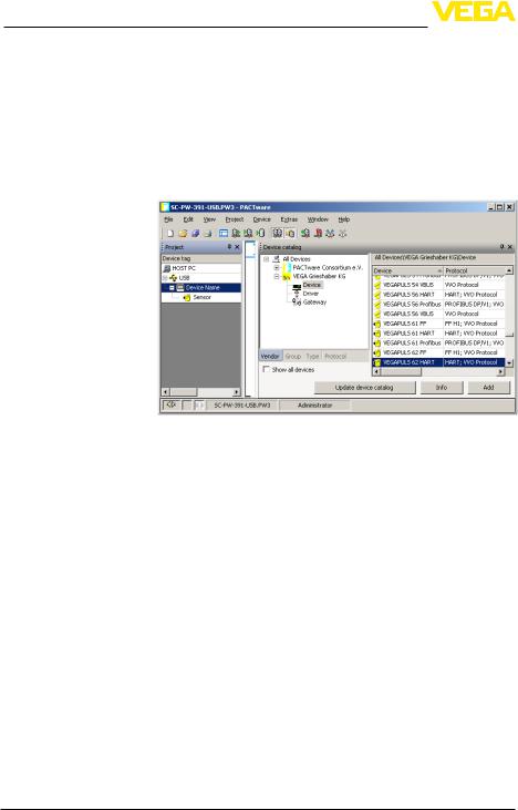
Project creation, VEGAMET 391 with sensor
The following example shows a typical project containing a sensor connected to aVEGAMET 391.Communication withVEGAMET 391 is carried out in this example via USB.We recommend using the "VEGA project assistant" as this considerably facilitates project creation and helps avoid errors.All participating components are found automatically and integrated into the project.
In case the planning is nevertheless carried out manually, e.g.when creating an offline project, the following DTMs must be added to the project tree:
RS232/Ethernet connection • VEGAMET 391/624/625, VEGASCAN 693, PLICSRADIO C62 |
9 |
4 Adjustment with PACTware
1.In the device catalogue, first select the "VEGA USB" DTM from the category "Driver" and transfer it, e.g.by double clicking, to the project window.
2.Select theVEGAMET 391 DTM from the category "Gateways" and transfer it into the project window.
3.Select the requested sensor DTM from the category "Device" and transfer it to the project window.
4.Now open the DTM by double clicking on the sensor in the project window and carry out the desired settings, see chapter "Parameter adjustment".
Connection, VEGAMET 624 via Ethernet
Fig. 2: Project with VEGAPULS
Project creation, VEGAMET 624 with sensor
The following example shows a typical project containing a sensor connected to aVEGAMET 624.Communication withVEGAMET 624 is carried out in this example via network and Ethernet.We recommend using the "VEGA project assistant" as this considerably facilitates project creation and helps avoid errors.All participating components are found automatically and integrated into the project.
In case the planning is nevertheless carried out manually, e.g.when creating an offline project, the following DTMs must be added to the project tree:
1.In the device catalogue, first select the "VEGA Ethernet" DTM from the category "Driver" and transfer it, e.g.by double clicking, to the project window.
2.Select theVEGAMET 624 DTM from the category "Gateways" and transfer it to the project window.
3.Select the requested sensor DTM from the category "Device" and transfer it to the project window.
4.Select the "VEGA-Ethernet" DTM in the project tree and select via the right mouse key the menu item "Additional functions - Change DTM addresses".Enter in the field "New address" the IP address or the Host name theVEGAMET should get later on in real operation.
10 RS232/Ethernet connection • VEGAMET 391/624/625, VEGASCAN 693, PLICSRADIO C62
130701-EN-30325
4 Adjustment with PACTware
5.Now open theVEGAMET DTM and sensor DTM by double clicking and carry out the desired settings, see chapter "Parameter adjustment".
Fig. 3: Project VEGAMET with VEGAPULS
30325-EN-130701
RS232/Ethernet connection • VEGAMET 391/624/625, VEGASCAN 693, PLICSRADIO C62 |
11 |
5 Application examples
5 Application examples
5.1Possible application areas
•VMI (Vendor Managed Inventory)
•Stock management of a tank farm via network and web browser
•Automatic transmission of levels, thresholds and fault messages via e-mail or SMS
•Remote enquiry of several tank farms via modem
•Measured value enquiry via Modbus-TCP
•Measured value enquiry via ACSII protocol
•Read out of measured value files via http
|
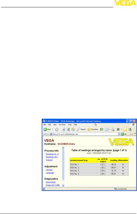
5.2 Inventory enquiry via network and browser |
Requirement |
The stock of a tank farm should be measured and monitored continu- |
|
ously.The measured values should be available to the scheduler and |
|
the sales department.In addition, a message should be triggered |
|
automatically if a level drops below a certain value. |
Solution |
One or more signal conditioning instruments with Ethernet interface |
|
enquire the respective sensors cyclically.The measured values are |
|
processed in the signal conditioning instrument and transferred in the |
|
requested form and unit to the integrated web server.The measured |
|
values can now be displayed on the computer of every user in the |
|
company network.In addition, the required minimum quantity is en- |
|
tered for each vessel.An e-mail is sent to the appropriate person via |
|
the company-internal mail system if a level falls below a certain value. |
|
Fig. 4: Measured value indication by means of web browser |
|
Setup |
• |
Connection of the sensors and signal conditioning instrument |
|
• |
Assignment of the HART sensor addresses (withVEGAMET 625 |
|
|
orVEGASCAN 693) |
12 RS232/Ethernet connection • VEGAMET 391/624/625, VEGASCAN 693, PLICSRADIO C62
130701-EN-30325

|
|
5 Application examples |
|
• |
Input of IP address/Host name, date/time on the signal condition- |
|
ing instrument |
|
|
• |
Installation of PACTware and DTMs on individual network PC |
|
• |
PACTwareParameter adjustment of the sensors (e.g.false echo memory) via |
|
• |
Parameter adjustment of the signal conditioning instrument |
|
(adjustment, scaling, linearization) via PACTware |
|
|
• |
Setup of the web and e-mail server |
|
• |
Indication of measured values via web browser by entering the |
|
|
Host name/IP address of the signal conditioning instrument |
|
5.3 Inventory enquiry/VMI via WEB-VV |
|
Requirement |
A supplier would like to keep track of the tank stock levels of his |
|
|
customers and replenish them on his own whenever necessary.Via a |
|
|
display that is updated several times daily, he has access to the level |
|
|
data of the previous days or weeks.The supplier can thus assess the |
|
|
requirements/consumption of his customers and plan his deliveries |
|
accordingly.This allows him to do anticipatory purchasing and also better utilize the capacity of his truck fleet.In addition, a message should be sent if the level in any tank falls below a certain predefined minimum value. Using this method, the supplier can always guarantee his customers a sufficient supply of raw materials for production without their having to bother with purchasing and ordering.And he has the added benefit of long-term customer retention and continuous orders.
30325-EN-130701
RS232/Ethernet connection • VEGAMET 391/624/625, VEGASCAN 693, PLICSRADIO C62 |
13 |

5 Application examples
|
Fig. 5: Remote enquiry via WEB-VV |
Solution |
A signal conditioning instrument with serial interface and modem |
|
(conventional telephone network or GSM) is installed at each cus- |
|
tomer.The measured values are transmitted automatically from each |
|
signal conditioning instrument to the centralWEB-VV server atVEGA. |
|
As an alternative, the measured value transmission can be also car- |
|
ried out via the Ethernet interface and the existing company network. |
|
The measured values can now be retrieved worldwide quickly and |
|
easily by any number of (authorized) persons via Internet and web |
|
browser.The current measured values as well as the history data are |
|
available as a line graph.A certain alarm threshold can be defined for |
|
each measurement loop.If a level falls below a predetermined value, |
|
an e-mail or SMS can be sent to certain persons. |
130701-EN-30325
14 RS232/Ethernet connection • VEGAMET 391/624/625, VEGASCAN 693, PLICSRADIO C62

6 PC/DCS values
6 PC/DCS values
6.1General information
PC/DCS outputs are used as digital outputs for transmission of measured value information.The data can be transmitted to a superordinate PC, DCS or processing system via the RS232/Ethernet interface. The values can be sent e.g.as e-mail or read out via ModbusTCP in case of an existing Ethernet interface.The HTML pages of the signal conditioning instrument also show the measured values of the PC/ DCS outputs.The adjustment of the data format and the reference value is carried out with PACTware and the corresponding DTM.In the parameter adjustment page "PC/DCS" the reference value and the data format are selected;in addition, the option "In case of error: transmit error code instead of measured value" can be activated.
Reference value |
With the reference value you determine which measured value is |
|
|
used as input signal for the PC/DCS output.The following reference |
|
|
values are available depending on the instrument: |
|
|
• |
Sensor value |
|
• |
Percent |
|
• |
Lin. percent |
|
• |
Scaled |
|
• |
Totalizer |
Data format |
With "Data format", the format of the PC/DCS value is determined. |
|
|
Here you determine how many decimal positions will be transmitted. |
|
|
This setting is important, e.g.with Modbus-TCP (filing of the meas- |
|
|
ured value as 2 Byte short).The PC/DCS value is then transmitted in |
|
|
the integer format, i.e.the value must be within the range of -32767 |
|
|
and +32767. |
|
|
Example: The sensor value of a pressure transmitter should be |
|
|
transmitted as PC/DCS value.The meauring range of the sensor is |
|
|
between -0.5 bar and +0.5 bar, the value should be transmitted with |
|
|
two positions after the decimal point.The following settings must |
|
|
be carried out:The sensor value must be selected as "Basic meas. |
|
|
value" and the selection #.## as "Data format".With these settings, |
|
|
the sensor value -0.5 bar is transmitted as PC/DCS value -0.5 bar. |
|
Fault |
If " In case of error: send error code instead of measured value " is ac- |
|
|
tivated, the number of the error code is sent instead of the measured |
|
|
value.These numbers correspond to the numbers of the instrument |
|
|
status. |
|
Example: With error E008, value 8 is transmitted instead of the measured value.
30325-EN-130701
RS232/Ethernet connection • VEGAMET 391/624/625, VEGASCAN 693, PLICSRADIO C62 |
15 |

7 Measured value enquiry viaWeb browser/http
7Measured value enquiry via Web browser/ http
7.1 General information
With an individual web browser (e.g.Internet Explorer) all measured values available in the signal conditioning instrument can be displayed in the requested form and unit.The measured value indication is carried out as HTML chart.Within a company network the enquiry is made via Ethernet.If a remote enquiry is necessary, a signal conditioning instrument with RS232 interface and connected modem is used.
The measured value enquiry can be also carried out via an individual http-capable software, e.g.Excel.
7.2 Access protection
To prevent unauthorised access to the measured values, the signal conditioning instrument can be provided with access protection.Use the web browser and enter the host name or the IP address of the instrument.Under "Settings - General" you can define the user name and the password and activate the access protection.When the page is called up, the default user name and password are asked for first of all.Enter "VEGA" for user name and password.Now you can activate the access protection for measured value enquiry and enter your own password.
The access protection applies also to measured value and instrument trend files which can be called up via http.
Note:
This access protection only prevents measured value enquiry via web browser.If the configuration of the signal conditioning instrument also needs to be protected against unauthorized access, a second access protection is available.This protection is configured with PACTware or the respective DTM.
7.3 Measured value enquiry via web browser/
|
• |
Ethernet |
Prerequisites |
Signal conditioning instrument with Ethernet interface |
|
|
• |
PACTware with suitable device DTM |
|
• |
mentEthernet connection at the site of the signal conditioning instru- |
|
• |
Windows-PC with Ethernet connection and web browser |
Setup |
First of all, enter the host name or IP address and subnet mask direct- |
|
|
ly via the adjustment unit of the signal conditioning instrument under |
|
|
"Device settings" (see operating instructions manual of the respec- |
|
|
tive instrument).Briefly interrupt the supply voltage, the instrument |
|
|
can then be accessed anywhere in the network via the host name |
|
|
and IP address.Install the configuration software PACTware with the |
|
appropriate DTMs for your instrument on any network PC.Now carry out the parameter adjustment of the individual measurement loops or
16 RS232/Ethernet connection • VEGAMET 391/624/625, VEGASCAN 693, PLICSRADIO C62
130701-EN-30325
30325-EN-130701
7 Measured value enquiry viaWeb browser/http
sensors as described in the respective operating instructions manual. Further information is available in chapter "Parameter adjustment with PACTware" as well as in the online help of PACTware or the DTM.
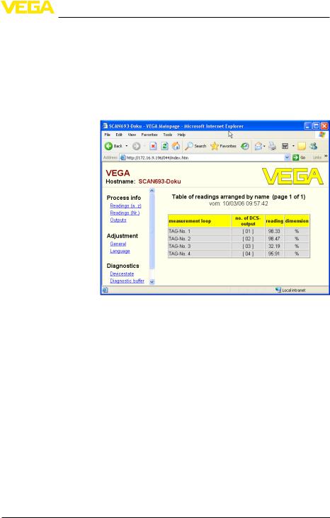
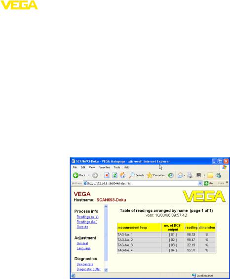
Measured value indica- Open the web browser (e.g.Internet Explorer) on any PC in your tion network.Enter the host name or the IP address in the field called "Address" or "URL".Now the HTML chart generated in the signal
conditioning instrument is displayed with all measured values in your browser window.This measured value enquiry can be carried out on any number of PCs in your network.
Fig. 6: Measured value indication by means of Internet Explorer
7.4Measured value enquiry via web browser/ RS232
Measured value enquiry via RS232 interface and PPP (Point to Point Protocol) is used if no internal company network or other direct connection is available.PPP is a transmission standard for serial connection between two computers (points).A dial-up line (telephone line) with a modem is usually used for this.
Measured value enquiry by means of web browser is a dial-in connection.The signal conditioning instrument accepts an incoming call and reacts to the calling host like an Internet Service Provider (ISP).This allows data exchange with the signal conditioning instrument via http. The dial-up connection makes it possible to access the HTML pages of the signal conditioning instrument with a web browser.
If a telephone connection is not available, a GSM wireless modem with RS232 interface can also be used.In this case, a GSM mobile phone contract with the option of data transmission is required.Make sure that your location is sufficiently covered by the network of the mobile network operator.In addition, the PIN of the SIM card used must be deactivated.
RS232/Ethernet connection • VEGAMET 391/624/625, VEGASCAN 693, PLICSRADIO C62 |
17 |

7 Measured value enquiry viaWeb browser/http
Prerequisites |
• |
Signal conditioning instrument with RS232 interface |
|
• |
PACTware with suitable device DTM |
|
• |
Modem with RS232 interface |
|
• |
Telephone connection at the location of the signal conditioning |
|
instrument (not necessary with GSM modem) |
|
|
• |
Windows PC with modem, telephone connection and web browser |
|
|
(e.g.Internet Explorer) |
Connection |
Connect the signal conditioning instrument to the PC with PACTware |
|
|
via the RS232 interface (see chapter "Connection").After the configu- |
|
ration, you can connect the modem instead of the PC.If changes are necessary later, you can access the instrument remotely via modem and carry out your settings.
Configuration of the RS232 interface of the signal conditioning instrument
Start PACTware with the suitable DTM and carry out the following configuration.
Communication protocol With this setting, you define which mode the RS232 interface should operate in.The following options are available:
•VVO protocol:Direct serial connection between signal conditioning instrument and PC for parameter adjustment and enquiry (e.g. with PACTware and DTM)
•PPP:Dial-up connection between signal conditioning instrument and modem for independent transmission of e-mails (dial-out connection) or enquiry via web browser (dial-in connection)
•ASCII protocol:Direct serial connection between signal conditioning instrument and PC for enquiry with terminal programs, e.g. Hyperterminal
1.Select the option "PPP" for connection of a modem for measured value enquiry via web browser.
Modem initialisation |
When connecting a modem, you should switch on this option so that it |
|
|
will be provided with parameters necessary for data transmission. |
|
Point to Point Protocol |
The Point to Point Protocol (PPP) enables the transmission of LAN |
|
|
protocols (e.g.http) via point-to-point connection.PPP connections |
|
|
are e.g.: |
|
|
• |
Switched connections via the analogue telephone network with |
|
analogue, ISDN and GSM modem |
|
|
• |
Standard connections |
|
2. When connecting a modem for measured value enquiry via |
|
|
|
web browser, select under "Dialing direction" the option "Dial-in |
|
|
(incoming connections)". |
|
3. Select in the navigation section "Dial-in" and enter the following |
|
|
|
data under "Settings for ISP emulation": |
User name |
4. Enter here an individual user name for your connection.This |
|
|
|
name must be used later on for the dial-up connection. |
18 RS232/Ethernet connection • VEGAMET 391/624/625, VEGASCAN 693, PLICSRADIO C62
130701-EN-30325
|
|
7 Measured value enquiry viaWeb browser/http |
|
Password/Password |
5. Enter here an individual password for your connection.This pass- |
||
|
|
word must be used later on for the dial-up connection. |
|
IP address |
6. Enter the preferred IP address.In general you can use the stand- |
||
|
|
ard setting "192.168.200.200". |
|
Host name |
7. Enter an individual name in the provided field. |
||
|
|
Create a dial-up connection on the PC |
|
|
|
First of all create a dial-up connection.UnderWindows 2000/Xp there |
|
|
|
is the "Assistent for new connection" which you can reach via "Start - |
|
|
|
Settings - Network connection".Proceed in the way you are creating |
|
|
|
a connection to the Internet via modem.Enter under Call number |
|
|
|
the telephone number of the local modem.Enter under User name/ |
|
|
|
Password the specifications already used for the signal conditioning |
|
|
|
instrument.Adjust a fix baud rate of 9600. |
|
Measured value indica- |
Now start your dial-up connection and establish the communication to |
||
tion |
the signal conditioning instrument. |
||
|
|
Open the web browser (e.g.Internet Explorer) and enter the previ- |
|
|
|
ously defined IP address in the field called "Address" or "URL".Now |
|
|
|
the HTML chart generated in the signal conditioning instrument is |
|
|
|
now displayed with all measured value in your browser window. |
|
30325-EN-130701
Fig. 7: Measured value indication by means of Internet Explorer
7.5 Measured value enquiry via http software
To enquire measured value files, an individual http capable software can be used.With Excel, the measured values can be readout automatically e.g.in an individual interval and saved as chart.Different formats of the measured value and status files are available.A detailed description of these file types is available in chapter "Measured value/
Status files".
Prerequisites |
• Signal conditioning instrument with Ethernet interface |
|
|
|
|
RS232/Ethernet connection • VEGAMET 391/624/625, VEGASCAN 693, PLICSRADIO C62 |
19 |
|

7 Measured value enquiry viaWeb browser/http
|
• |
PACTware with suitable device DTM |
|
• |
mentEthernet connection at the site of the signal conditioning instru- |
|
• |
IP address/Subnet mask for each signal conditioning instrument |
|
suitable for the network |
|
|
• |
Windows-PC with Ethernet connection and http-capable software |
Measured value files |
The PC/DCS values can be retrieved in four different file formats via |
|
|
http.Use the following command:http://ip-address or Host name/file |
|
|
name, e.g.http://192.168.200.200/val.htm. |
|
|
• |
val.txt (text file) |
|
• |
val.csv (CSV file) |
|
• |
val.htm (HTML file) |
|
• |
val.xml (XML file) |
Status files |
In addition to the measured value file there is also a status file with |
|
|
status, relay and current output information.For retrieval via http, use |
|
|
the following command:http://ip-address or Host name/file name, e.g. |
|
|
http://192.168.200.200/state.htm. |
|
|
• |
state.txt (text file) |
|
• |
state.csv (CSV file) |
|
• |
state.htm (HTML file) |
|
• |
state.xml (XML file) |
130701-EN-30325
20 RS232/Ethernet connection • VEGAMET 391/624/625, VEGASCAN 693, PLICSRADIO C62
Loading...