


 Loading...
Level and Pressure
Operating Instruction
Capacitive electrodes EK …
with signal conditioning instrument

Safety information
Safety information
The described module must only be installed and operated as described in this operating instruction. Please note that other action can cause damage for which VEGA does not take responsibility.
Note Ex-area
Please note the attached approval documents (yellow binder) and especially the included safety data sheet.
2 |
Capacitive electrodes EK with signal conditioning instrument |

Contents
Contents
|
Safety information ........................................................................ |
2 |
|
|
Note Ex-area ................................................................................ |
2 |
|
1 |
Product description |
|
|
|
1.1 |
Function and configuration .................................................. |
4 |
|
1.2 |
Types and versions ............................................................. |
6 |
|
1.3 |
Technical data ....................................................................... |
8 |
|
1.4 |
Approvals ........................................................................... |
14 |
|
1.5 |
Dimensions ......................................................................... |
15 |
|
1.6 |
Type plate ........................................................................... |
17 |
2 |
Mounting |
|
|
|
2.1 |
Mounting instructions ......................................................... |
18 |
3 |
Electrical connection |
|
|
|
3.1 |
Connection instructions ..................................................... |
23 |
|
3.2 |
Wiring plan .......................................................................... |
24 |
4 |
Set-up |
|
|
|
4.1 |
General adjustment ........................................................... |
27 |
|
4.2 |
Level detection ................................................................... |
28 |
|
4.3 |
Continuous level measurement ......................................... |
29 |
5 |
Diagnosis |
|
|
|
5.1 |
Simulation ............................................................................ |
31 |
|
5.2 |
Maintenance ....................................................................... |
31 |
|
5.3 |
Repair .................................................................................. |
31 |
|
5.4 |
Failure removal ................................................................... |
32 |
Capacitive electrodes EK with signal conditioning instrument |
3 |
Product description
1 Product description
1.1 Function and configuration
Capacitive electrodes series EK detect levels of virtually any medium, unaffected whether liquids, powders, granules or pastes. This is also valid for adhesive mediums.
The electrode measures also the level capacitance and the ohmic resistance (admittance processing). Hence also problematic mediums and solids with fluctuating humidity contents can be detected.
By the use of screening tubes and screen segments, inactive areas can be provided on the probe where pollution, condensation or permanent build-up do not influence the measuring result.
Measuring principle
Electrode, medium and vessel wall form an electrical capacitor.
The capacitance of the capacitor is mainly influenced by three factors:
-distance of the electrode plates (a)
-size of the electrode plates (b)
-kind of dielectricum between the electrodes (c)
 b
b
c
Fig. 1.1 Plate capacitor (schematic demonstration)
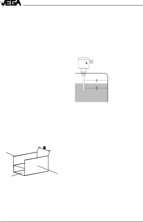
Electrode and vessel wall are the capacitor plates. The medium is the dielectricum. Due to the higher dielectric constant figure (DKvalue) of the medium against air, the capacitance of the capacitor increases with raising covering of the electrode.
Fig. 1.2 Capacitance change with covered electrode
The capacitance change is converted by the oscillator into a level proportional, floating current in the range of 4 … 20 mA or into a switching command.
Continuous level measurement
With the continuous level measurement, the appropriate level is continuously detected and converted into a level proportional signal which is either directly indicated or further processed.
You require a capacitive electrode series EK with oscillator and a signal conditioning instrument VEGAMET, converting the proportional current of the oscillator into standardised current and voltage signals.
The continuous measurement requires a constant dielectric constant figure er, i.e. if possible the medium should have steady features.
4 |
Capacitive electrodes EK with signal conditioning instrument |

Product description
The floating signal of the electrode electronics is in the range 4 … 20 mA and can be therefore connected without additional potential separation to other processing systems such as e.g. VEGALOG.
In addition to the continuous measurement, also levels can be detected (VEGAMET or VEGAMET + VEGASEL).
Level detection
Level switches should signal when certain levels are reached, e.g. max. or min. levels. These levels are detected at a fixed point and converted into a switching command.
For level detection capacitive electrodes EK with appropriate signal conditioning instruments VEGATOR are available. A switching command can be either triggered when the electrode is covered or uncovered.
Capacitive electrodes EK with signal conditioning instrument |
5 |

Product description
1.2 Types and versions
|
|
|
Type*) |
EK |
EK |
EK |
EK |
EK |
EK |
Version |
11 |
21 |
24 |
26 |
31 |
42 |
|||
Continuous |
• |
• |
• |
|
• |
• |
|||
Level detection |
• |
• |
• |
• |
• |
• |
|||
Partly insulated |
• |
|
|
|
• |
|
|||
Fully insulated |
|
• |
• |
• |
|
• |
|||
Oscillators |
|
|
|
|
|
|
|||
E 14 |
|
• |
• |
|
|
• |
• |
||
E 15 |
|
• |
• |
|
|
• |
• |
||
E 15 Ex |
• |
• |
|
|
• |
• |
|||
E 17 |
|
• |
• |
|
|
• |
• |
||
E 17 Ex |
• |
• |
|
|
• |
• |
|||
E 18 |
|
• |
• |
• |
• |
• |
• |
||
E 18 Ex |
• |
• |
• |
• |
• |
• |
|||
Approvals |
|
|
|
|
|
|
|||
CENELEC EEx ia IIC T6 |
• |
• |
• |
• |
• |
• |
|||
PTB-Zone 0 EEx ia IIC T6 |
• |
• |
• |
• |
• |
• |
|||
Overfill protection |
|
|
|
|
|
|
|||
acc. to WHG |
• |
• |
• |
• |
• |
• |
|||
German Lloyd1) |
• |
• |
• |
• |
• |
• |
|||
Lloyds Register of Shipping1) |
• |
• |
• |
• |
• |
• |
|||
American Bureau of Shipping1) |
• |
• |
• |
• |
• |
• |
|||
Bureau Veritas1) |
• |
• |
• |
• |
• |
• |
|||
RINA1) |
• |
• |
• |
• |
• |
• |
|||
Mechanical connection |
|
|
|
|
|
|
|||
G 3/ |
4 |
A |
• |
• |
• |
• |
• |
• |
|
G 1 A |
• |
• |
• |
• |
• |
• |
|||
3/ |
" NPT |
• |
• |
• |
• |
• |
• |
||
4 |
|
|
|
|
|
|
|
|
|
1“ NPT |
• |
• |
• |
• |
• |
• |
|||
Flange plated |
|
• |
|
• |
|
|
|||
Electrode material |
|
|
|
|
|
|
|||
Steel |
|
|
• |
|
• |
|
|
||
StSt |
|
|
•2) |
•2) |
•3) |
|
•4) |
•3) |
|
Isolating material5) |
|
|
|
|
|
|
|||
PTFE |
|
• |
• |
|
• |
• |
|
||
FEP |
|
|
|
|
• |
|
|
• |
|
PE |
|
|
|
• |
• |
|
|
• |
|
6 |
Capacitive electrodes EK with signal conditioning instrument |

Product description
Type*) |
EK |
EK |
EK |
EK |
EK |
EK |
Version |
11 |
21 |
24 |
26 |
31 |
42 |
Concentric tube |
|
|
|
|
|
|
StSt |
• |
• |
|
|
|
|
|
|
|
|
|
|
|
|
|
|
|
|
|
|
Screening tube (option) |
|
|
|
|
|
|
StSt |
• |
• |
|
• |
• |
• |
Temperature adapter |
|
|
|
|
|
|
(option) |
|
|
|
|
|
|
StSt |
• |
• |
|
• |
• |
|
Housing material |
|
|
|
|
|
|
Plastic (IP 66) |
• |
• |
• |
• |
• |
• |
Aluminium - plastic coated |
|
|
|
|
|
|
(IP 66 and 67) |
• |
• |
• |
• |
• |
• |
Others |
|
|
|
|
|
|
Bending of |
|
|
|
|
|
|
electrode 6) |
• |
•7) |
|
|
|
|
*) All instrument types also Ex0
1)applied
2)1.4435
3)1.4571
4)1.4401
5)For electrodes certified for Ex-Zone 0, only PTFE and FEP are approved as isolating material.
6)Bending max. 90°
7)EK 21 only with PTFE with 3,2 mm isolation thickness
Capacitive electrodes EK with signal conditioning instrument |
7 |

|
|
|
|
Product description |
1.3 Technical data |
|
|
||
Housing |
|
|
||
Housing material |
plastic PBT (Polyester) or Aluminium |
|||
|
|
|
plastic coated |
|
Protection |
|
|
||
- |
plastic housing |
IP 66 |
|
|
- |
Aluminium housing |
IP 66 and 67 (meets both protections) |
||
Cable entry |
1 pce. M20 x 1,5 |
|||
Terminals |
for max. 1,5 mm2 cross-section area of |
|||
|
|
|
conductor |
|
Mechanical connection |
|
|
||
Material |
1.4435 (316 L) |
|||
Thread |
G 3/4 A or 3/4“ NPT |
|||
|
|
|
G 1 A or 1“ NPT |
|
Flange |
flange versions, plated |
|||
Electrode |
|
|
||
Material |
EK 11 |
1.4435 (316 L) |
||
|
|
|
EK 21 |
steel (St 37), 1.4435 (316 L) |
|
|
|
EK 31 |
1.4401 (316 L) |
|
|
|
EK 24, 42 1.4571 (316 L) |
|
Length |
|
|
||
- |
rod |
max. 3 m |
|
|
- |
cable |
max. 20 m |
|
|
Isolation |
see "Isolating materials" |
|||
Max. tensile strength |
|
|
||
- |
EK 31 |
3 KN |
|
|
- |
EK 42 |
3 KN |
|
|
Ambient conditions |
|
|
||
Ambient temperature on the housing |
-40°C … +80°C |
|||
Medium temperature |
see "Product temperature and operating |
|||
|
|
|
pressure" |
|
Storage and transport temperature |
-40°C … +80°C |
|||
Operating pressure |
see "Product temperature and operating |
|||
|
|
|
pressure" |
|
Oscillators E14, E15, E17, E18 |
|
|
||
Protection class |
II |
|
||
Overvoltage category |
III |
|
||
Meas. frequency |
see table on the following page |
|||
Capacitance ranges |
see table on the following page |
|||
Supply voltage |
12 … 36 V DC (powered by signal conditioning |
|||
|
|
|
instrument) |
|
Potential separation |
min. 500 V DC (except E14) |
|||
8 |
Capacitive electrodes EK with signal conditioning instrument |

Product description
For Ex-applications note the permissible electrical connection values stated in the certificate.
Load in W
Supply voltage in V
Accessory
Straining spring of 1.4571 (EK 42, EK 52, EK 53)
- |
load |
approx. 185 mm (stressed) |
- |
tensile load |
approx. 200 N |
Weight |
|
|
Basic weight (e.g. EK 24) |
approx. 0,8 kg |
|
Rod weight |
ø 6 mm - 0,23 kg/m |
|
|
|
ø 10 mm - 0,62 kg/m |
Cable weight (EK 31) |
approx. 40 g/m |
|
Capacitive electrodes EK with signal conditioning instrument |
9 |

|
|
|
|
|
Product description |
|
Oscillators in two-wire technology for capacitive electrodes EK |
|
|
||||
|
|
|
|
|
|
|
Type |
Application |
Meas. range |
Frequency |
|
Signal cond.instr. |
|
E14 |
Level detection in general |
I: 0 … 25 pF |
400 kHz |
|
VEGATOR |
|
|
|
|
II: 0 … 100 pF |
|
|
VEGALOG |
|
|
|
III: 0 … 400 pF |
|
|
|
E15 |
Level detection in general |
I: 0 … 25 pF |
400 kHz |
|
VEGATOR |
|
|
with potential separation |
II: 0 … 100 pF |
|
|
VEGALOG |
|
|
|
|
III: 0 … 400 pF |
|
|
|
E15 Ex |
as E15, however for use in |
I: 0 … 25 pF |
400 kHz |
|
VEGATOR Ex |
|
|
hazardous areas acc. to |
II: 0 … 100 pF |
|
|
VEGALOG 1) |
|
|
CENELEC, PTB zone 0 as well as |
III: 0 … 400 pF |
|
|
|
|
|
zone 1 and StEx zone 10 and as |
|
|
|
|
|
|
part of an overfill protection acc. to |
|
|
|
|
|
|
WHG, (VbF) |
|
|
|
|
|
E17 |
Continuous level measurement in |
I: 0 … 120 pF |
40 kHz |
|
VEGAMET |
|
|
general or level detection with |
II: 0 … 600 pF |
|
|
VEGALOG |
|
|
potential separation |
III: 0 … 3000 pF |
|
|
(VEGATOR) |
|
E17 Ex |
as E17, however for use in |
I: 0 … 120 pF |
40 kHz |
|
VEGAMET Ex |
|
|
hazardous areas acc. to |
II: 0 … 600 pF |
|
|
VEGALOG 1) |
|
|
CENELEC, PTB zone 0 as well as |
III: 0 … 3000 pF |
|
|
(VEGATOR Ex) |
|
|
zone 1 and StEx zone 10 and as |
|
|
|
|
|
|
part of an overfill protection acc. to |
|
|
|
|
|
|
WHG, (VbF) |
|
|
|
|
|
E18 2) |
Continuous level measurement |
I: 0 … 120 pF |
470 kHz |
|
VEGAMET |
|
|
or level detection with potential |
II: 0 … 600 pF |
|
|
VEGALOG |
|
|
separation acc. to the principle of |
III: 0 … 3000 pF |
|
|
(VEGATOR) |
|
|
phase selective admittance proces- |
|
|
|
|
|
|
sing especially for adhesive mediums |
|
|
|
|
|
|
and for the use in solids with |
|
|
|
|
|
|
varying humidity |
|
|
|
|
|
E18 Ex 2) |
as E18, however for the use in |
I: 0 … 120 pF |
470 kHz |
|
VEGAMET Ex |
|
|
hazardous areas acc. to |
II: 0 … 600 pF |
|
|
VEGALOG 1) |
|
|
CENELEC, PTB zone 0 as well as |
III: 0 … 3000 pF |
|
|
(VEGATOR Ex) |
|
|
zone 1 and StEx zone 10 and as |
|
|
|
|
|
|
part of an overfill protection acc. to |
|
|
|
|
|
|
WHG, (VbF) |
|
|
|
|
|
1)with safety barrier
2)see following page
10 |
Capacitive electrodes EK with signal conditioning instrument |
Product description
Oscillator E18 |
Level |
|
fully insulated |
measured value |
|
||
|
|
electrode |
|
|
|
|
|
The oscillator E18 with the patented process- |
|
15 % vol. |
|
ing (phase selective admittance processing) |
+ |
|
|
extends the application range of capacitive |
1) |
|
|
level measurement technology. |
– 0 % 5 % |
10 % |
Solid |
|
|
humidity (%) |
|
|
|
|
|
In conjunction with the fully insulated rod |
|
|
partly insu- |
electrode EK 24 the oscillator E18 compen- |
|
|
|
|
|
lated elec- |
|
sates even very conductive build-up. |
1) Actual value level |
|
trode |
Mounted in an individual rod or cable elec- |
Fig. 1.3 Humidity change |
|
|
trode type EK, E18 ensures also the exact |
|
|
|
measurement in solids with varying humidity |
|
|
|
contents. |
|
|
|
The oscillator E18 processes the measuring currents according to their phase position. Measuring current with a defined phase shifting as they occur with build-up or humidity changes are filtered out.
Humidity change
A humidity change in solids causes a change of the dielectric constant figure (er). In parallel the ohmic value of the medium changes. Due to the change also a phase shifting of the measuring currents is caused.
With a capacitive measurement already lowest humidity changes cause measuring errors. Typical products are e.g. sand, aggregate in the cement industry, hop or plastic granules (after drying).
When using the oscillator E18 humidity changes of 15 % vol. do not influence the accuracy of the measurement. Even layering of product with different humidity does not play a role for the measuring accuracy.
When the humidity contents exceeds 15 % vol., fully and partly insulated electrodes react differently (see also "Fig. 1.3 Humidity change“). Whereby the measured value on fully insulated electrodes raises with steady level, the measured value on partly insulated electrodes drops.
Capacitive electrodes EK with signal conditioning instrument |
11 |
Loading...