


SPARE PART AND OPERATION MANUAL FOOD MIXER
Models W30(A), W40(A), W40P, W60(A) and W60P

Caution -READ BEFORE OPERATINGCaution
Varimixer recommends that mixer operators be at least 18 years of age and be thoroughly trained on the use of the mixer.
Varimixer recommends that the following precautions be adopted to help make the mixer operation safer and more efficient.
-All operators should be at least 18 years of age.
-All operators should be thoroughly trained before being allowed to operate the mixer.
-NEVER reach into the bowl when the mixer is running.
-Do not wear loose clothing or rings while operating the mixer.
-Stop the mixer and lower the bowl before adding ingredients, scraping the bowl, removing the agitator, or removing the product.
-Stop the mixer before removing or installing attachments into the drive hub.
-Do not attempt to assemble or disassemble attachments while mounted into the drive hub.
-Always use the pusher plate with the slicer/meat grinder attachments.
-NEVER bypass the safety mechanisms supplied on the mixer. Doing so can cause injury and is the responsibility of the user to insure these safety mechanisms are operating properly.

LIMITED WARRANTY
Varimixer warrants its commercial mixers to the original purchaser against defects in material or manufacture for a period of one year from the date of original purchase, subject to the following exclusions and limitations. The warranties provided by Varimixer do not apply in the following instances:
EXCLUSIONS
1. In the event that the equipment is improperly installed. Proper installation is the responsibility of the installer, proper installation procedures are covered in the Varimixer Spare Parts and Operations Manual. .
2.In the event that the equipment is improperly maintained. Proper maintenance is the responsibility of the user. Proper maintenance procedures are covered in the Varimixer Spare Parts and Operations Manual.
3.In the event that failure or malfunction of the appliance or any part thereof is caused by abnormal use or is otherwise not attributa-
ble to a defect in material or manufacture. |
. |
4.In the event that the appliance , by whatever cause, has been materially altered from the condition in which it left the factory.
5.In the event that the rating plate has been altered or removed.
6. On parts which would normally be worn or replaced under normal conditions. .
7. With regard to adjustments and/or calibrations. Checking of and changes in adjustments and calibrations are the responsibility of the installer, Proper installation is the responsibility of the installer, proper installation procedures are covered in the Varimixer Spare Parts and Operations Manual. .
If any oral statements have been made regarding the appliance, such statements do not constitute warranties and are not part of the contract of sale. This Limited Warranty constitutes the complete, final and exclusive statement with regard to warranties.
..THIS LIMITED WARRANTY IS EXCLUSIVE AND IS IN LIEU OF ALL OTHER WARRANTIES WHETHER ..
..WRITTEN, ORAL OR IMPLIED, INCLUDING, BUT NOT LIMITED TO, ANY WARRANTY OF..
..MERCHANTABILITY OR FITNESS FOR PARTICULAR PURPOSE OR WARRANTY AGAINST LATENT..
..DEFECTS.
LIMITATIONS OF LIABILITY
In the event of warranty claim or otherwise, the sole obligation of Varimixer shall be the repair and/or replacement at the option of Varimixer, of the appliance or component or part thereof Such repair or replacement shall be the expense of Varimixer except that travel over 100 miles or two hours, overtime, and holiday charges shall be,, the expense of the purchaser. Any repair or replacement under this warranty does not constitute an extension of the origin, warranty for any period for the appliance or for any component part thereof. Parts to be replaced under this warranty will be repaired or replaced at the option of Varimixer with new or functionally operative parts. The liability of Varimixer on any claim of any kind, including claims based on warranty, expressed or implied, contract, negligence, strict liability or any other theories shall be solely and exclusively the repair or replacement of the product as stated herein, an such liability shall not include, and purchaser specifically renounces any rights to recover, special, incidental, consequential or other damages of any kind whatsoever, including, but not limited to, injuries to persons or damage to property, loss of profits or anticipated profits, or loss of use of the product.
TO SECURE WARRANTY SERVICE
If you claim a defect covered by this Limited Warranty, first direct your claim to the local Authorized Service Agency, giving model, serial and code numbers, voltage, a description of the problem and your sales slip. If this procedure fails to be satisfactory to you, you may write to the Varimixer National Service Manager, 5489 Campus Dr, Shreveport, Louisiana 71129; you should include the information listed above.
TABLE OF CONTENTS
Installation Instructions................................................................................................... |
2 |
Operating Instructions..................................................................................................... |
3 |
Cleaning-Maintenance.................................................................................................... |
4 |
Belt Adjustments and Removal....................................................................................... |
5 |
Adjusting the Bowl Height............................................................................................... |
7 |
Machine Column.......................................................................................................... |
9 |
Bowl Arms..................................................................................................................... |
11 |
Planetary Head............................................................................................................. |
13 |
Transmission................................................................................................................. |
15 |
Speed Lever Assembly.................................................................................................. |
17 |
Single Speed Transmission........................................................................................... |
19 |
Attachment Drive.......................................................................................................... |
21 |
Instrument Panel........................................................................................................... |
23 |
Bowl Screen.................................................................................................................. |
27 |
Vegetable Slicer............................................................................................................ |
29 |
Meat Mincer ................................................................................................................. |
37 |
Bowl Scraper................................................................................................................. |
43 |
Tools and Bowls............................................................................................................ |
47 |
Bowl Truck.................................................................................................................... |
47 |
Electrical Diagrams....................................................................................................... |
49 |
1
Read this page entirely BEFORE beginning installation.
VARIMIXER INSTALLATION INSTRUCTIONS
UNDER NO CIRCUMSTANCES ARE THE SPEED LEVER, BOWL LIFT LEVER, OR THE BOWL ARMS TO BE USED TO MOVE THE MIXER INTO PLACE. DAMAGE WILL RESULT TO THE UNIT. IT IS RECOMMENDED THAT THE TOP LID BE REMOVED BEFORE MOVING THE UNIT.
The mixer must be mounted with the rubber feet, which neutralize both shaking and rusting. Spacers can be inserted under the mixer’s feet if the floor is uneven. The mixer can be bolted to the floor if desired.
Before the mixer is connected to power, it should be checked that the voltage and frequency on the rating plate is correct in relation to the place of installation. A unit labeled 220V 3 Phase will operate from 208V to 240V 3 phase safely. The rating plate is located on the rear right side of the mixer. The electrical connection box is located at the top rear of the mixer.
WARNING
Electrical and grounding connections must comply with applicable portions of the National Electrical Code and/or other local electrical codes.
Wire Color Codes
White-Phase 1
Red -Phase 2
Black-Phase 3
Green-Ground
No Neutral is used
1. Lower the bowl lift lever. |
2. Remove the bowl and all tools. |
3. Raise the bowl lift. |
4. Close bowl screen if equipped. 5. Turn timer to 10 minutes and push “start” .
6. Insure cover is rotating in the correct direction.
2
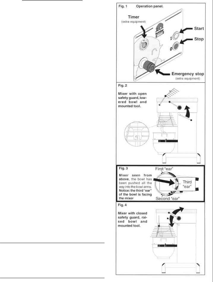
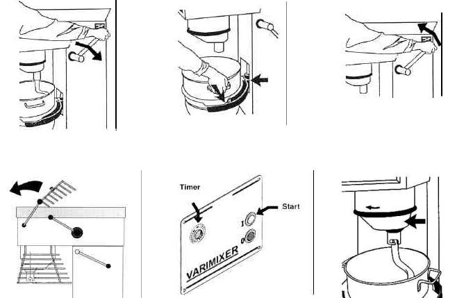
OPERATION OF THE MIXER:
A)Open the bowl screen and place the bowl in the bowl arms. Note: The bowl arms must be in lowest position and the bowl must be pushed all the way into the bowl arms.(Fig.3).
B)Place the mixing tool in the bayonet shaft. The pin on the tool must be turned into the bayonet hole (fig.2).
C)The bowl is raised to working position, ensure that the bowl is placed correctly. Close the bowl screen. If the mixer is equipped with a timer, set the mixing time required by turning the timer (fig 1) clockwise. The mixer will stop automatically, when the time runs out. When the mixer has timed out, the "procedure for starting after emergency stop" is used before the mixer is re-started.
D)Start the mixer by pressing the green start button (fig.1)
The mixer will only start when the bowl is in "up"position, the bowl screen is closed,and the timer is set to time or "hold".
E)Turn the speed selector lever (fig. 4) to the rear until the required speed has been obtained, (notice the recommended maximum speeds on page 3).
F)Before the mixer is stopped, the speed selector lever must be moved back to lowest speed (fig.4).
G)Stop the mixer by pressing the red stop button (fig.1)
PROCEDURE FOR STARTING AFTER EMERGENCY STOP:
1)This procedure must be used in cases where the mixer has been interrupted in high speed.
2)Lower the bowl and remove the tool from the bayonet.
3)Raise the bowl arms, either empty or with the bowl.
4)Close the safety guard, start the mixer and move
the speed selector lever back to lowest speed. Switch off the mixer. Now the mixer can be started as usual.
OVERLOAD
Do not overload the mixer. Sticky and heavy doughs may reduce the capacity of the bowl by 75%. The capacity is further reduced if the speed of the mixing tool is increased beyond recommended values or if an incorrect mixing tool is used. Large lumps of fat or cooled ingredients MUST be cut into small parts before they are placed into the bowl or damage can occur to the mixing tool(s).
3

Correct use of tools: |
Maintenance and Lubrication: |
Whips should never be struck against hard objects, this will decrease the life of the tool.
Recommended applications for tools:
Whip |
Beater |
Hook |
Cream |
Cakes |
Pizza |
Egg Whites |
Waffles |
Bread |
Mayonnaise |
Muffins |
Donut |
and the like. and the like. Doughs and the like.
Cleaning:
The mixer should be cleaned daily or after use.The mixer should be cleaned with a soft cloth and clean water. Sulphonated soaps should be used with caution as they destroy the mixer's lubricants.
Never use high pressure cleaning for the mixer.
Bowls and tools of aluminium must not be washed with strong alkaline detergents (pH not bigger than 9.0).
The soap suppliers can recommend the correct type of soap.
The mixer should be unplugged before cleaning to prevent accidental starting while cleaning.
The inside of the beater shaft should be cleaned once a day with warm, soapy water.
Dough hook Cleaning: Special care should be given to cleaning the dough hook. We recommend that it be cleaned and sanitized in a commercial dish machine. An alternate cleaning procedure is to vigorously scrub the hook with a hot.water and detergent solution. Use a heavy bristled brush. After cleaning, sanitize the hook by rinsing it with a 50 ppm solution of sodium hypochlorite.
The variable speed pulleys must be lubricated regularly, i.e. a lubrication interval of approx. 60 hours of operation.
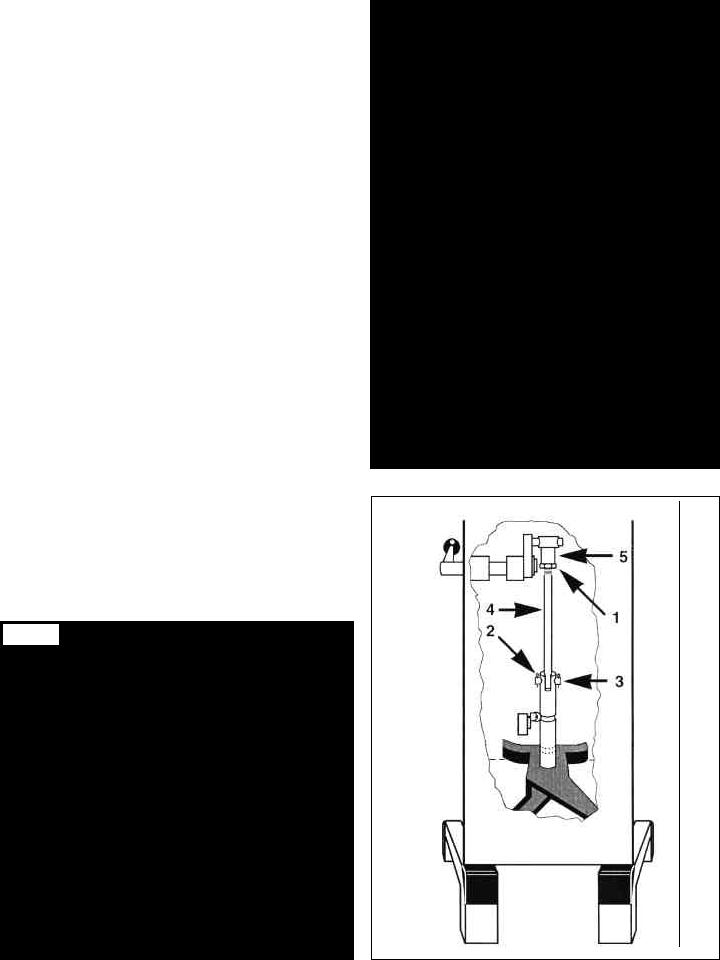
Lubrication of variable speed pulleys:
-Start the mixer and increase the speed to approx. 50%. Stop the mixer and open the lid on the top of the mixer. On the top of each of the two pulley set shafts is a grease nipple (fig. 5 point 1). Press grease through the grease nipples until the grease gun feels hard to press or until grease comes out between the shaft and the pulleys.
-Start the mixer, and set the speed back to low speed.
-Stop the mixer and fill the grease gun with new grease so that it is ready for next time.
Lubrication of other movable parts:
The movable parts of the bowl arms, the shaft and the lifting rod must also be lubricated with oil. Remove the rear covering and lubricate the marked points with an oil can. (fig.5 pkt.2)
Grease Types:
-Grease for the pulley set shafts: Lubriplate # 1200-2
-On repair of the planetary head: Grease the toothed wheel and the toothed rim with Nye Gel 868VH,(PN 868VH), the needle bearings in the planetary head must not be lubricated with this type of grease, they should be lubricated with PN Sapphire 2. Do not use any another type of grease than the one stated here.
-On repair of the attachment drive: Fill the attachment drive with Tribol Molub 860/150-0, (PN 860/150-0).
Fig.5
4
Belt Adjustments and Removal
To remove V-belts or tooth belt:
1.Remove the 4 screws (T) from the control panel.
2.Remove the front control (U) from mixer and let hang from cables.
3.Open lid.
4.Remove nut (J) and washers (H).
5.Remove fork assembly (X).
6.Roll belt (A) off of the the pulleys and remove.
7.Lossen jam nut (E) and tension bolt (F).
8.Loosen bolts (D).
9.Remove 3 V-belts or single tooth belt from planetary pulley (Y) and pedestal assembly (S).
To install V-belts or single tooth belt:
1.Install the 3 V-belts (C) on the pedestal pulley and planetary pulley (Y).
2.Tighten the 2 bolts (D) on the pedestal assembly, insure the v-belts are tight.
3.Install special v-belt (A).
4.Install fork assembly (X).
5.Install washers (G) (H) and nut (J). DO NOT TIGHTEN NUT!
6.On the front pulley set, the stud (K) on the varispeed collar (L) must be placed inside the lower fork (M), and outside
...the fork on the rear pulley set (N).
7.Start the mixer and tighten the nut (J).
8.Using the speed adjustment lever , lower the speed until the belt (A) is 1/8” from the outside edge of the front var-
....speed pulley (S). THIS IS LOW SPEED. Adjust the 2 jamnuts (R) against the fork (X) and tighten. This is your low
....speed setting.
9.Using the speed adjustment lever , increase the speed until the belt (A) is 1/8” from the outside edge of the rear var-
....speed pulley (L). THIS IS HIGH SPEED. Adjust the bolt (O) down against the motor plate and tighten the jamnut. This
....is the high speed setting.
10.Using the speed adjustment lever , lower the speed to low. Turn off mixer and set the speed indicator arrow to 70 ....
......R.P.M.
5

6
ADJUSTMENT OF BOWL HEIGHT:
The distance (X) is measured from the bottom side of the bayonet hole to the surface on the bowl arms on which the bowl rests (fig.7a). The bowl arms must be lifted to normal working position.
|
W30 = 6 |
3/8” |
(X): |
W40 = 6 3/8” |
|
|
W60 = 6 |
15/16” |
Lower the bowl arms down on a wooden block so that the weight of the bowl arms are not loading the lifting system. Loosen the counter nut (1), (fig.7b). Take out the cotter pin
(2). Take out the lifting rod (3). The lifting bolt (4) is now loose and can be turned out or into the lifting nut (5), until the correct height of the bowl arms has been reached.
ADJUSTMENT OF BOWL FIXING:
The bowl arms must be raised to normal working position. Loosen the counter nuts (1) and remove the cotter pins (2). Turn the bolt (3) until correct fixing of the bowl is achieved. By turning the bolts out of the extension tube the fixing is increased. Start by turning one of the bolts half a revolution.
ADJUSTMENT OF BOWL CENTERING:
Loosen the counter nuts (1) and remove the cotter pins (2). Turn the bolt (3) until the bowl is in the center of the mixer. After the fixing of the bowl, one of the bolts must be turned out of the extension tube and the other into the extension tube. Use the flat beater to check that the bowl is correctly centered and turn the planetary head with your hand before the voltage is connected.
Fig.7A
7
8
19
|
16 |
|
|
|
3 |
18 |
14 |
15 |
|
||
|
|
|
|
23 |
|
|
|
17 |
|
22 |
|
25
26
24
6
|
|
10 |
20 |
27 |
10 |
|
|
4 |
|
29 |
5 |
|
28 |
|
|
|
|
|
|
12 |
9 |
|
13 |
|
|
8
30
1.
Bowl Lift Microswitches
1986 - Present
Pre 1996 |
1997-2001 |
|
|
|
|
|
|
2001Present |
|
|||||||||||||
|
|
|
|
|
|
|
|
|
|
|
|
|
|
|
PN 2781-173172 |
|
||||||
PNPN2727-172- |
|
PN 27140-172-173 |
|
|||||||||||||||||||
|
|
|
|
|
|
|
|
|
|
|
|
|
|
|
|
|
|
|
|
|
|
|
|
|
|
|
|
|
|
|
|
|
|
|
|
|
|
|
|
|
|
|
|
|
|
|
|
|
|
|
|
|
|
|
|
|
|
|
|
|
|
|
|
|
|
|
|
|
9

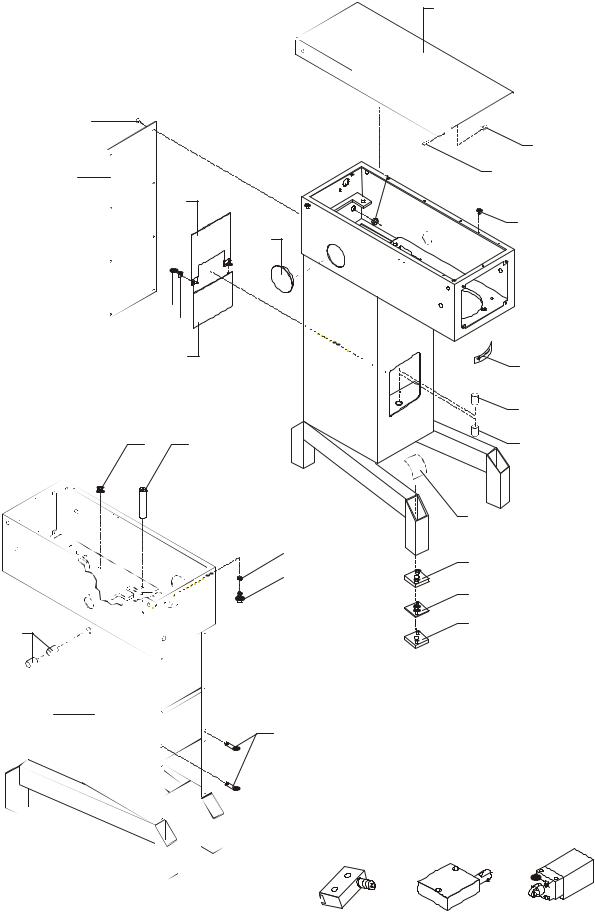
MACHINE COLUMN
|
|
DESCRIPTION |
|
|
PART NUMBER |
|
|
|
|
|
W30(A) |
W40(A) |
W40P |
W60(A) |
W60P |
1. |
Bowl Lift Microswitch |
See Figure |
See Figure |
See Figure |
See Figure |
See Figure |
|
2. |
Mounting Screws |
STA 5270 |
STA 5270 |
STA 5270 |
STA 5270 |
STA 5270 |
|
3. Top Lid Threaded Bushing |
STA 6580 |
STA 6580 |
STA 6580 |
STA 6580 |
STA 6580 |
||
4. |
Knee Pad |
30N-212 |
30N-212 |
30N-212 |
60N-212 |
60N-212 |
|
5. |
Intermediate Piece 6 MM |
30N-214.6 |
30N-214.6 |
30N-214.6 |
60N-214.6 |
60N-214.6 |
|
6. |
Indicator Arrow |
15-245 |
15-245 |
15-245 |
15-245 |
15-245 |
|
8. |
Column |
30N-22 |
30N-22 |
30N-22 |
60N-22 |
60N-22 |
|
9. |
Lift Lever Bushings |
STA 2515 |
STA 2515 |
STA 2515 |
STA 2515 |
STA 2515 |
|
10. |
Bowl Arm Shaft Bushings |
STA 2520 |
STA 2520 |
STA 2520 |
STA 2520 |
STA 2520 |
|
12. |
Intermediate Piece 3 MM |
30N-214.3 |
30N-214.3 |
30N214.3 |
60N-214.3 |
60N-214.3 |
|
13. |
Foot |
30N-213 |
30N-213 |
30N-213 |
60N-213 |
60N-213 |
|
15. |
Lid Screw |
STA 5017 |
STA 5017 |
STA 5017 |
STA 5017 |
STA 5017 |
|
16. |
Access Plate Screw |
STA 5080 |
STA 5080 |
STA 5080 |
STA 5080 |
STA 5080 |
|
17. |
Ground Screw |
STA 5232 |
STA 5232 |
STA 5232 |
STA 5232 |
STA 5232 |
|
18. |
Rear Access Plate |
27-22.7 |
27-22.7 |
27-22.7 |
60-22.7 |
60-22.7 |
|
19. |
Top Lid |
27-21 |
27-21 |
27-21 |
60-21 |
60-21 |
|
20. |
Plug Button Rear Screen |
31-306 |
31-306 |
31-306 |
31-306 |
31-306 |
|
22. |
Plug Button No Hub |
15-73 |
15-73 |
15-73 |
15-73 |
15-73 |
|
23. |
Upper NSF Plate Cover |
31-270 |
31-270 |
31-270 |
61-270 |
61-270 |
|
24. |
Lower NSF Plate Cover |
31-271 |
31-271 |
31-271 |
61-271 |
61-271 |
|
25. |
Lock Nut NSF Plate |
STA 5834 |
STA 5834 |
STA 5834 |
STA 5834 |
STA 5834 |
|
26. Washer |
STA 6027 |
STA 6027 |
STA 6027 |
STA 6027 |
STA 6027 |
||
27. |
Motor Mount |
31-148M4 |
31-148M4 |
31-148M4 |
61-148M4 |
61-148M4 |
|
28. |
Motor Mount Bolt |
STA 5625 |
STA 5625 |
STA 5625 |
STA 5625 |
STA 5625 |
|
29. |
Lock Washer |
STA 6056 |
STA 6056 |
STA 6056 |
STA 6056 |
STA 6056 |
|
30. |
Roll Pin |
30-70.1 |
30-70.1 |
30-70.1 |
30-70.1 |
30-70.1 |
|
|
|
|
|
|
|
|
|
10
 Loading...