


FOOD MIXER
SPARE PART AND OPERATION MANUAL |
Model W20 A, J, F |
|
March 2007 |
||
1993 to Present |
||
Form 103 |
||
|

Caution -READ BEFORE OPERATINGCaution
Varimixer recommends that mixer operators be at least 18 years of age and be thoroughly trained on the use of the mixer.
Varimixer recommends that the following precautions be adopted to help make the mixer operation safer and more efficient.
-All operators should be at least 18 years of age.
-All operators should be thoroughly trained before being allowed to operate the mixer.
-NEVER reach into the bowl when the mixer is running.
-Do not wear loose clothing or rings while operating the mixer.
-Stop the mixer and lower the bowl before adding ingredients, scraping the bowl, removing the agitator, or removing the product.
-Stop the mixer before removing or installing attachments into the drive hub.
-Do not attempt to assemble or disassemble attachments while mounted into the drive hub.
-Always use the pusher plate with the slicer/meat grinder attachments.
-NEVER bypass the safety mechanisms supplied on the mixer. Doing so can cause injury and is the responsibility of the user to insure these safety mechanisms are operating properly.
LIMITED WARRANTY
Varimixer warrants its commercial mixers to the original purchaser against defects in material or manufacture for a period of one year from the date of original purchase, subject to the following exclusions and limitations. The warranties provided by Varimixer do not apply in the following instances:
EXCLUSIONS
1. In the event that the equipment is improperly installed. Proper installation is the responsibility of the installer, proper installation procedures are covered in the Varimixer Spare Parts and Operations Manual. .
2.In the event that the equipment is improperly maintained. Proper maintenance is the responsibility of the user. Proper maintenance procedures are covered in the Varimixer Spare Parts and Operations Manual.
3.In the event that failure or malfunction of the appliance or any part thereof is caused by abnormal use or is otherwise not attributa-
ble to a defect in material or manufacture. |
. |
4.In the event that the appliance , by whatever cause, has been materially altered from the condition in which it left the factory.
5.In the event that the rating plate has been altered or removed.
6. On parts which would normally be worn or replaced under normal conditions. .
7. With regard to adjustments and/or calibrations. Checking of and changes in adjustments and calibrations are the responsibility of the installer, Proper installation is the responsibility of the installer, proper installation procedures are covered in the Varimixer Spare Parts and Operations Manual. .
If any oral statements have been made regarding the appliance, such statements do not constitute warranties and are not part of the contract of sale. This Limited Warranty constitutes the complete, final and exclusive statement with regard to warranties.
..THIS LIMITED WARRANTY IS EXCLUSIVE AND IS IN LIEU OF ALL OTHER WARRANTIES WHETHER ..
..WRITTEN, ORAL OR IMPLIED, INCLUDING, BUT NOT LIMITED TO, ANY WARRANTY OF..
..MERCHANTABILITY OR FITNESS FOR PARTICULAR PURPOSE OR WARRANTY AGAINST LATENT..
..DEFECTS.
LIMITATIONS OF LIABILITY
In the event of warranty claim or otherwise, the sole obligation of Varimixer shall be the repair and/or replacement at the option of Varimixer, of the appliance or component or part thereof Such repair or replacement shall be the expense of Varimixer except that travel over 100 miles or two hours, overtime, and holiday charges shall be,, the expense of the purchaser. Any repair or replacement under this warranty does not constitute an extension of the origin, warranty for any period for the appliance or for any component part thereof. Parts to be replaced under this warranty will be repaired or replaced at the option of Varimixer with new or functionally operative parts. The liability of Varimixer on any claim of any kind, including claims based on warranty, expressed or implied, contract, negligence, strict liability or any other theories shall be solely and exclusively the repair or replacement of the product as stated herein, an such liability shall not include, and purchaser specifically renounces any rights to recover, special, incidental, consequential or other damages of any kind whatsoever, including, but not limited to, injuries to persons or damage to property, loss of profits or anticipated profits, or loss of use of the product.
TO SECURE WARRANTY SERVICE
If you claim a defect covered by this Limited Warranty, first direct your claim to the local Authorized Service Agency, giving model, serial and code numbers, voltage, a description of the problem and your sales slip. If this procedure fails to be satisfactory to you, you may write to the Varimixer National Service Manager, 5489 Campus Dr, Shreveport, Louisiana 71129; you should include the information listed above.
TABLE OF CONTENTS
Installation Instructions................................................................................................... |
2 |
|
Cleaning |
Instructions..................................................................................................... |
2 |
Operating |
Instructions.................................................................................................... |
3 |
Specifications...................................................................................................... |
4 |
|
Service Instructions......................................................................................................... |
5 |
|
Main Body..................................................................................................................... |
11 |
|
Bowl Arms..................................................................................................................... |
13 |
|
Pulley System................................................................................................... |
..........15 |
|
Planetary Head............................................................................................................. |
17 |
|
Attachment Drive.......................................................................................................... |
19 |
|
Front Control Panel/ Electrical Components................................................................. |
21 |
|
Bowl Screen.................................................................................................................. |
25 |
|
Tools and Bowls............................................................................................................ |
27 |
|
Electrical Diagrams....................................................................................................... |
29 |
|
1
INSTALLATION - CLEANING - MAINTENANCE
INSTALLATION:
The mixer can be placed directly on the floor. Foundation bolts in the floor are necessary only under special conditions, e.g. in ships.
If the 20-quart mixer is placed on a bench stand, it must be fastened with the bolts that fasten the unit to the
shipping pallet.
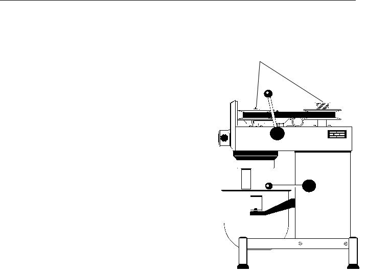
Ensure that the voltage, phase and hertz printed on the identification plate of the mixer are the same as that at the place of installation. The identification plate is located at the top of the right side of the mixer. Be sure the mixer is properly connected to the incoming power supply and the ground or earth connection is made. The arrow on the front of the planetary head (see drawing 2, page 1), indicates the direction of rotation of the planetary head. On three-phase motors the direction of rotation can be changed by interchanging two phases of
the connecting cable or the motor. Electrical connections must be made in accordance with local regulations.
DOUGH HOOK CLEANING:
Special care should be given to cleaning the dough hook. The Varimixer dough hook is manufactured of stainless steel and we recommend that it be cleaned and sanitized in a commercial dish machine. An alternate cleaning procedure is to vigorously scrub the dough hook with a hot water and detergent solution. Use a heavy bristled brush. After cleaning, sanitize the dough hook by rinsing with a 50 ppm solution of sodium hypochlorite.
CLEANING:
The mixer should be cleaned daily or after use. Wash with a soft brush and pure water. Synthetic detergents should be used with care as they destroy the lubricants of the mixer. Washing with a hose is not recommended. Bowls and mixing tools should be washed in detergents which do not attack aluminum. Detergent suppliers will be able to recommend the right type.
LUBRICATION AND MAINTENANCE:
When the mixer is used regularly, the varispeed system must be lubricated approximately once each month. When the mixer is extensively used, or used often without changes in speed, lubrication intervals should be shorter.
DIRECTIONS FOR LUBRICATION:
Start the mixer and increase the speed to approximately 50%. Stop
the mixer and remove the top cover by removing the two screws (2), see page 2-3.
A grease nipple is located at the top of each of the pulley sets. Press the grease through the grease nipples until the grease gun feels hard, or until grease is pressed out between the shaft and the pulleys.
Replace the top cover and remember to replace the two screws securing the cover. The lid must be mounted before starting the mixer.
Start the mixer and set the speed back to low.
Stop the mixer and fill the grease gun with new grease to be prepared for the next lubrication.
TYPES OF GREASE:
Grease for the shafts of the pulley sets: Lubriplate 1200-2, or another ball bearing grease: NLGI1 or NLGI 2.
When repairing the planetary head (which is greased for life) the grease (PN 868VH) should be used in the gear wheel, gear wheel rim. The needle bearings of the planetary head should be greased with PN Sapphire 2 The needle bearings must not be greased with the PN 868 VH type of grease.
Use only this type grease and do not mix with other types of grease.
2
Varimixer Operating Instructions W20
|
|
|
|
|
|
|
|
|
|
|
|
|
|
|
|
|
|
|
|
|
|
|
|
|
|
|
|
|
|
|
|
|
|
|
|
|
|
|
|
|
|
|
|
|
|
|
|
|
|
|
|
|
|
|
|
|
|
|
|
|
|
|
|
|
|
|
|
|
|
|
|
|
|
|
|
|
|
|
|
|
|
|
|
|
|
|
|
|
|
|
|
|
|
|
|
|
|
|
|
|
|
|
|
|
|
|
|
|
|
|
|
|
|
|
|
|
|
|
|
|
|
|
|
|
|
|
|
|
|
|
|
|
|
|
|
|
|
|
|
|
|
|
|
|
|
|
|
|
|
|
|
|
|
|
|
|
|
|
|
|
|
|
|
|
|
|
|
|
|
|
|
|
|
|
|
|
|
|
|
|
|
|
|
|
|
|
|
|
|
|
|
|
|
|
|
|
|
|
|
|
|
|
|
|
|
|
|
|
|
|
|
|
|
|
|
|
|
|
|
|
|
|
|
|
|
|
|
|
|
|
|
|
|
|
|
|
|
|
|
|
|
|
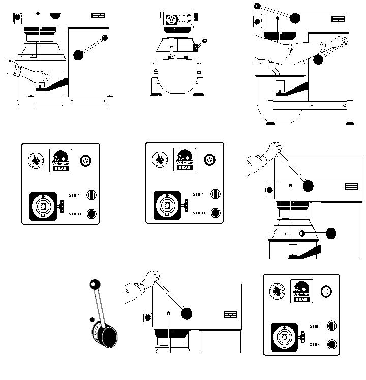
Place the bowl in the bowl arms. Be sure |
Place the mixing tool in the bayonet shaft. |
Raise the bowl to working position by |
||||||||||||||||||||||||
pulling the handle forward. Ensure that the |
||||||||||||||||||||||||||
that the bowl is placed correctly and the |
The pin of the tool must be turned into the |
|||||||||||||||||||||||||
bowl is placed correctly while the bowl is |
||||||||||||||||||||||||||
bowl clamps are used. |
bayonet hole. |
|||||||||||||||||||||||||
lifted. Close the bowl screen. |
||||||||||||||||||||||||||
|
|
|
|
|
|
|
|
|
|
|
|
|
|
|
||||||||||||
|
|
|
|
|
|
|
|
|
|
|
|
|
|
|
|
|
|
|
|
|
|
|
|
|
|
|
|
|
|
|
|
|
|
|
|
|
|
|
|
|
|
|
|
|
|
|
|
|
|
|
|
|
|
|
|
|
|
|
|
|
|
|
|
|
|
|
|
|
|
|
|
|
|
|
|
|
|
|
|
|
|
|
|
|
|
|
|
|
|
|
|
|
|
|
|
|
|
|
|
|
|
|
|
|
|
|
|
|
|
|
|
|
|
|
|
|
|
|
|
|
|
|
|
|
|
|
|
|
|
|
|
|
|
|
|
|
|
|
|
|
|
|
|
|
|
|
|
|
|
|
|
|
|
|
|
|
|
|
|
|
|
|
|
|
|
|
|
|
|
|
|
|
|
|
|
|
|
|
|
|
|
|
|
|
|
|
|
|
|
|
|
|
|
|
|
|
|
|
|
|
|
|
|
|
|
|
|
|
|
|
|
|
|
|
|
|
|
|
|
|
|
|
|
|
|
|
|
|
|
|
|
|
|
|
|
|
|
|
|
|
|
|
|
|
|
|
|
|
|
|
|
|
|
|
|
|
|
|
|
|
|
|
|
|
|
|
|
|
|
Set the time required by turning the timer to |
Start the mixer by pressing the green start |
Push the speed selector lever to obtain |
||||||||||||||||||||||||
the required speed. The speed must be |
||||||||||||||||||||||||||
the right. The mixer will stop automatically |
button. The mixer will only start with the |
|||||||||||||||||||||||||
changed only when the mixer is |
||||||||||||||||||||||||||
when the time runs out. |
timer on and the bowl screen closed. |
|||||||||||||||||||||||||
running. |
||||||||||||||||||||||||||
|
|
|
|
|
|
|
|
|
|
|
|
|
|
|
||||||||||||
|
|
|
|
|
|
|
|
|
|
|
|
|
|
|
|
|
|
|
|
|
|
|
|
|||
|
Dough Hook |
|
|
|
|
|
|
|
|
|
|
|
|
|
|
|
|
|
|
|
||||||
|
|
|
|
|
|
|
|
|
|
|
|
|
|
|
|
|
|
|
|
|||||||
|
|
|
|
|
|
|
|
|
|
|
|
|
|
|
|
|
|
|
|
|||||||
|
100 R.P.M. |
|
|
|
|
|
|
|
|
|
|
|
|
|
|
|
|
|
|
|
||||||
|
|
|
|
|
|
|
|
|
|
|
|
|
|
|
|
|
|
|
|
|||||||
|
|
|
|
|
|
|
|
|
|
|
|
|
|
|
|
|
|
|
|
|||||||
|
Flat Beater |
|
|
|
|
|
|
|
|
|
|
|
|
|
|
|
|
|
|
|
||||||
|
250 R.P.M |
|
|
|
|
|
|
|
|
|
|
|
|
|
|
|
|
|
|
|
||||||
|
Wire Whip |
|
|
|
|
|
|
|
|
|
|
|
|
|
|
|
|
|
|
|
||||||
|
|
|
|
|
|
|
|
|
|
|
|
|
|
|
|
|
|
|
|
|||||||
|
400 R.P.M. |
|
|
|
|
|
|
|
|
|
|
|
|
|
|
|
|
|
|
|
||||||
|
|
|
|
|
|
|
|
|
|
|
|
|
|
|
|
|
|
|
|
|
|
|
|
|
|
|
|
|
|
|
|
|
|
Before the mixer is stopped, the speed |
|
|
|
|
|
|
|
|
|
|
|
||||||||
|
Recommended maximum speeds |
selector lever should be moved to the low- |
Stop the mixer by pressing the red stop |
|||||||||||||||||||||||
|
est speed. The mixer must not be started |
button. |
||||||||||||||||||||||||
|
|
|
|
|
|
|
||||||||||||||||||||
|
|
|
|
|
|
|
when loaded in high speed position. |
|
|
|
|
|
|
|
|
|
|
|
||||||||
|
|
|
|
|
|
|
|
|
|
|
|
|
|
|
|
|
|
|
|
|
|
|
|
|
|
|
|
|
|
|
|
|
|
|
|
|
|
|
|
|
|
|
|
|
|
|
|
|
|
|
|
|
|
OVERLOADING: Do not overload the mixer. Tough and heavy doughs might reduce the working capacity of the mixer by 75%. The capacity will be further reduced if the speed of the tool is increased beyond what is recommended, or if a wrong tool is used. Big lumps of grease or cooled ingredients must be divided into fine particles before being placed into the bowl. A long period of overloading will cause the thermal overload relay to stop the mixer. Let the mixer rest for approximately three minutes and press the RED STOP button BEFORE pressing the GREEN START button.
If the mixer is stopped in high speed when loaded, the bowl is to be removed from the mixer and the speed set to low speed before the bowl is placed in the mixer again.
WARNING: Bodily harm could result from placing hands into the bowl while the mixer is running.
3

Varimixer Specifications W20
Dimesion Data |
|
|
Level Capacity of large bowl |
Qt. |
21 |
Level Capacity of small bowl |
Qt. |
13 |
Width Overall |
In. |
17 7/8 |
Depth Overall |
In. |
26 1/2 |
Height Overall |
In |
34 7/8 |
Electrical Data for Motor** |
|
|
60HZ / 1 Phase |
|
|
Voltage* |
V |
115 |
Feed Wires incl. Ground |
No. |
3 |
Motor Power |
HP |
1 |
Amperes,full load |
A |
12 |
Mixing Speed |
|
|
Agitator Speed |
Min. |
100 |
Agitator Speed |
Max. |
400 |
Attachment Hub |
R.P.M. |
90-420 |
Shipping Data |
|
|
Basic Machine plus 1 s/s bowl,1 set of standard tools |
|
|
Measurement |
|
|
Shipping Box |
|
|
Width |
In. |
28 ½ |
Depth |
In. |
30 ½ |
Height |
In. |
46 ½ |
Volume |
Cu.Ft. |
23.4 |
Weight Data |
|
|
Net Weight |
Lbs. |
196 |
Gross Weight |
Lbs. |
233 |
Capacity Chart |
|
|
|
|
|
|
|
||
Mashed |
Potatoes |
|
Whip |
or |
Beater |
17 |
lbs. |
||
Whipped Cream |
|
Whip |
|
|
4 Qts. |
||||
Muffins |
|
|
|
Beater |
|
|
24 |
lbs. |
|
Layer |
Cake |
|
|
Beater |
|
|
23 |
lbs. |
|
Pie Dough |
|
|
Pastry |
Knife |
21 |
lbs. |
|||
Pancake |
Batter |
|
|
Whip |
or |
Beater |
9 |
Qts. |
|
Cookie |
Dough |
|
|
Beater |
or |
Hook |
14 |
lbs. |
|
Donuts,Yeast |
|
|
Hook |
|
|
20 |
lbs. |
||
Donuts,Cake |
|
|
Beater |
|
|
23 |
lbs. |
||
Bread |
Dough |
(65% |
AR) |
Hook |
|
|
25 |
lbs. |
|
Pizza |
Dough |
(50% |
AR)*** |
Hook |
|
|
12 |
lbs. |
|
%AR= weight of water weight of flour
*On the nominal motor voltage + or – 10% tolerance is allowed. **Also available in 220/60/1 , 220/50/1 , 110/50/1. Not submitted
for UL listing.
***Varimixer also features our Model W20P , specifically designed for pizza and pretzel dough.
Specifications are subject to change without notice.
4

SERVICE INSTRUCTIONS
6 |
|
10 |
|
1 |
|
22 |
|
7 |
|
9 |
|
41 |
|
40 |
|
|
|
|
|
|
|
|
|
|
|
|
|
|
|
|
|
|
|
|
|
|
|
|
|
|
|
|
|
|
8
55
3
21
4
5
17 |
|
18 |
|
20 |
|
19 |
16
2
43
44
42
5
SERVICE INSTRUCTIONS
(1) Remove the top cover of the mixer (1) and the plastic cover (43) by removing the 2 screws
(3) The attachment engagement hub is taken out by removing the plastic cover (4) and the 4 bolts (5).
(6)The control box is taken off by removing the 2 screws (55).
(7)The special V-belt is replaced in the following way:
a)Remove the top cover of the mixer (1) and the plastic cover (43).
b)Press the speed selector lever (8) back toward the back of the mixer so that the special V-belt is loosened, and take off the special V-belt.
c)The special V-belt is mounted by first placing it on the rear pulley set (9) (the motor pulley set) and opening the pulleys by pulling the special V-belt.
d)Turn the speed selector lever (8) back toward the back of the mixer (high speed) and mount the special V- belt on the front pulley set (10).
e)Adjust the speed (see page 8).
(9)The motor pulley set is taken off in the following way:
a)Remove the top cover of the mixer (1), the plastic cover (43), the special V-belt (7)
b)The motor pulley set can now be taken off by loosening the~ 2 screws (40). The upper half of the pulley set can be taken off by removing the circlip (41).
(21)Relay and thermal overload relay are taken out in the following way:
a)Remove the top cover of the mixer (1), the plastic cover (43), the special V-belt (7), and the control panel
(6).
b)Loosen the screws (22).
c)If the relay is to be replaced, the screw (57) is removed.
Before relay and thermal overload relay are taken out, the mixer must (for safety reasons) be disconnected on the main switch or the connecting cable disconnected.
The indicator (23) on the side of the thermal overload relay is adjusted to the rated current of the motor + 10%.
(42) The motor is removed in the following way: |
|
|
|
|
|
||
|
|
|
|
23 |
|||
a) |
Switch off the voltage to the mixer or disconnect the connect- |
|
|
22 |
|
||
57 |
|||||||
ing cable. |
|
|
|
|
|||
|
|
|
|
||||
|
|
|
|
|
|||
b) |
Remove the top cover of the mixer (1), the plastic |
|
|
|
|
|
|
cover (43), the special V-belt (7), and the motor pulley set (9). |
|
|
|
|
|
||
c) |
Remove the motor cable from the connecting box (44) of the |
|
|
|
|
|
|
motor. |
|
|
|
|
|
|
|
d) |
Place the mixer on its back. |
|
|
|
|
|
|
e) |
Remove the legs of the mixer (17) and the bottom plate (19). |
|
|
|
|
|
|
f) |
The motor can be pulled out backwards by removing the 4 |
|
|
|
|
|
|
bolts (16)
6
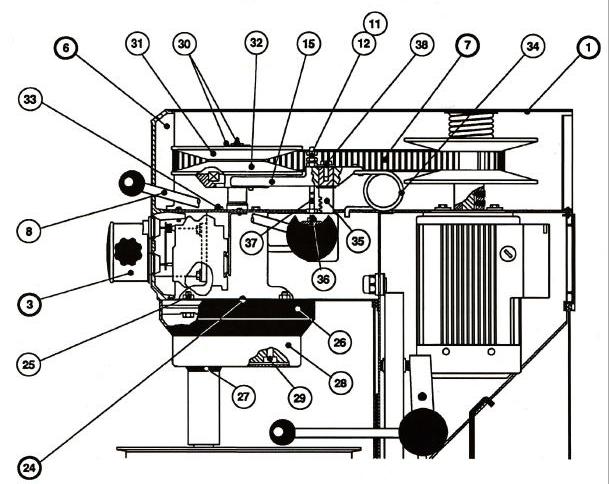
The planetary head is removed in the following way:
a)The top cover of the mixer (1), the attachment engagement hub (3), the special V-belt (7), and the control box (6) are removed.
b)The plastic ring (26) can be removed by knocking it gently on the front edge, then pressing a screwdriver between the plastic ring and the metal plate at the top of the plastic ring.
c)Remove the rubber ring (27).
d)The stainless headcap (28) can now be removed by knocking it gently on the front edge with a plastic hammer, turning the planetary head 1800, and again knocking gently on the front edge.
e)If only the lower part of the planetary head is to be repaired, the planetary head can be separated by removing the 3 bolts (29).
f)Remove the grease nipple and washer (30), and pull off the upper half of the pulley set (31) with an extrac-
tor.
g)Take off the movable part (32) of the pulley set. h) Take off the 4 screws (33).
h)The spring (34) is removed in the following way: The nuts (11) and (12) are removed. The lower fork (15), the toothed rack (35) and the spring (34) will come up also when the nut (12) is removed. If the toothed rack (35) is to be replaced, this can be done when the lower fork (15) is free. Remove the bolt (38) and the toothed rack can be replaced.
i)When the counter nut and the pointed screw (36) are removed, the speed selector lever (8) can be removed.
k) Remove the pin bolt (37) by loosening the counter nut.
I) By loosening and removing the 4 bolts (25), the planetary head can be lowered.
7
C |
|
B |
See Drawing
A
8
|
|
32 |
|
35 |
|
15 |
|
34 |
|
7 |
39 |
|
|||||||||
|
|
|
|
|
|
|
|
|
|
|
|
|
|
|
|
|
|
|
|
|
|
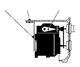
Mounting of the planetary head should be done in reverse order.
When the lower fork (15) and the spring (34) are mounted, the speed selector lever (8) is turned counter clockwise, so that it points horizontally backward, at the same time as the lower fork is pressed down gently. When the speed selector lever (8) is turned clockwise, it
will catch the toothed rack (35) and pull down the lower fork. Screw Drawing A on the nuts (11) and (12).
Be aware that the pin (39) on the lower part (32) of the pulley set is to be placed as shown in the drawing above.
When all parts have been mounted, the speed must be adjusted.
15
Adjustment of speed and belt
9
16
11
12
38
14
13
a)Adjust the distance (8) 12.6", by loosening the 4 bolts (16) and moving the motor back and forth. The tolerance of the
.....distance (B) can be used in cases where there are problems in adjusting the speed correctly, as the distance (B) is
.....dependent on the tolerance of the special V-belt.
b)Loosen the lock nut (11) and the adjusting nut (12).
c)Start the mixer and adjust the lowest speed so that the special V-belt (7) is approximately 1/16 to 1/8" (C) from
.....the pulley edge.
d)Stop the mixer and tighten the adjusting nut (12) loosely and then the lock nut (11)
e)Loosen the lock nut (13) and the adjusting screw (14).
f)Start the mixer and adjust the highest speed so that the special V-belt (7) is approximately 1/16 to 1/8" (C) from the pulley edge of the motor pulley set (9).
g)Stop the mixer and tighten the adjusting screw (14) loosely and then the lock nut (13).
h)Start the mixer and control the measure (C) on both pulley sets at high and low speed, respectively.
i)Be aware that the pin (39) on the lower part (32) of the pulley set is to be placed as shown on the drawing above.
Tolerances in the transmission can cause the special V-belt (7) to hit the pins of the pulley sets when the speed has been adjusted. In these cases, the distance (B) is to be reduced and the speed readjusted.
8
 Loading...