Valley Acrylic PRO6632SKLWHT, OVO60322SSKLWHT, ESPACE5430SKRBIS, PSPACE5432SKLBIS, PSPACE5430SKRBIS Installation Manual
...
Installation Manual
Introduction
Thank you for choosing a Valley product! This installation manual provides you with general information on the proper installation of our bath products.
IMPORTANT NOTE: Never lift or carry your unit by the grab bar, or by any piping if equipped with a whirlpool system. These elements are not designed for carrying, and doing so may result in damage to the unit, or bodily injury. Carrying your unit in this manner will void your warranty.
Before you begin
•Read this instruction manual carefully before beginning your installation.
•Consult your local building codes when installing your tub.
•Remove the unit from its packaging. Inspect your unit carefully to ensure there is no damage before receiving your unit from your sales representative, and before disposing of your packaging. Damage can occur during shipping, and responsibility ceases upon delivery of the product in good order to the carrier. All complaints regarding damage due to transport must be made directly to the carrier.
•It is recommended that you place the unit in the bathroom before beginning installation.
•To protect the unit during installation, we suggest laying it onto a piece of flat cardboard rather than on the floor itself.
•Do not remove the polyethylene protective film until installation is complete to gain maximum protection. Do remove it where two surfaces will be in permanent contact.
•The floor must be level and strong enough to support the weight of the water-filled bathtub.
•Verify that all dimensions on the plan are the same as on your unit.
•If an apron is being installed, ensure that your floor covering material can fit between the apron & the floor.
•If your bathtub is equipped with both a whirlpool, and an air system, space must be made for the air system’s blower either inside or outside the alcove, or island. If the blower cannot be installed under the bathtub, it can be located up to 9 feet away.
•Make sure an access panel, recommended to be at least 30” x 30” (750mm x 750mm), is located near the whirlpool pump and/or the air system blower to allow easy servicing.
•Access must be provided for each product component (water heater, light, nozzle, electronic and air control, faucet).
•Whirlpool and/or air systems must be connected before final installation (see the Installation and user’s guide for whirlpool and air systems).
•Dedicated GFI (Ground Fault Interrupter) circuits are required on electrical components ie) Comfort warm heater, Jetting, Chromatherapy, & Aromatherapy. Check your local electrical code for full details.
Structure installation
Do not build the surrounding structure before receiving your unit. Structure measurements should be verified against the unit to ensure a proper fit.

Tools required
•Measuring tape
•Pencil
•3/16” (5 mm) and 1/8” (3mm) drill bits
•Hole saw
•Electric drill
•Screwdriver
•Pliers
•Level
•Safety glasses
•Silicone sealant
•Wood wedges
•2” x 2” x 3” wood blocks (51 mm x 51 mm x 76 mm)
•No.8 x 1 1/4” screws (4.2 mm x 32 mm - Flat or Phillips head)
•3/4” x 1” wood studs (19 mm x 25 mm) for alcove installation.
Plumbing
Make sure you install all plumbing, and drainage before securing the unit. It is always recommended to have a certified, professional plumber to perform the installations.
Before drilling a hole in the floor for your drain pipe, ensure that there are no hidden elements beneath. (Pipes, floor joists, heating ducts, electrical wires, etc)
Leveling & support
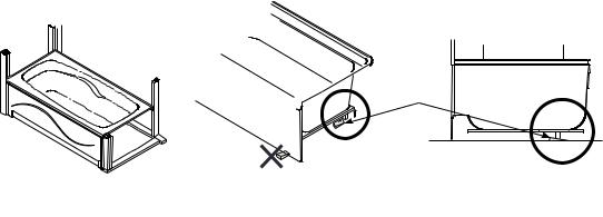
The unit must be installed perfectly level. Level your unit using wooden wedges a xed to the floor beneath the wooden base, or using mortar cement. All legs must be in contact with the floor. If leveling does not permit this, it is imperative to add a wood wedge to support your bath or shower.
To provide additional support, sound-proofing, & levelling, it is recommended that a layer of mortar be applied to the base of the bathtub’s legs, and covered with a 1/16” (2mm) polyethylene sheet. The layer should be thick enough to facilitate the levelling of the unit without raising it. Once the unit is in position, ensure it is level in both directions for proper draining.
Leveling must be done under the wood legs located beneath the unit. Do not level directly behind or under the unit’s front flange.
Wood shim
Do not shim under the front flange
The frame, and plumbing must be completed according to the instructions before installing the unit in your bathroom. If it is renovation work, the wall surfaces will have to be removed in order to allow for the installation of the unit to the appropriate structural frame.
IMPORTANT NOTE: Check local building codes to ensure that the floor can support your tub’s filled weight.
 Loading...