


HD-19
ClearVIEW HD-19
©2012 Vaddio - All Rights Reserved ● WallVIEW HD-19 DVI/HDMI ● Document Number 342-0267 Rev. C
V
V
A
A
D
D
D
D
I
I
O
O
™
™
W
W
A
A
L
L
L
L
V
V
I
I
E
E
W
W
™
™
H
H
D
D
-
-
1
1
9
9
D
D
V
V
I
I
/
/
H
H
D
D
M
M
I
I
With Quick-Connect™ DVI/HDMI - SR with HSDS™ and the
CONCEAL Wall Mounting System for the Vaddio™ HD-19 Robotic
Pan/Tilt/Zoom Camera
Quick-Connect DVI/HDMI SR Interface
PN: 998-1105-018
INSTALLATION AND USER GUIDE
Arctic White Version
Part Number 999-6946-000AW (North America)
Part Number 999-6946-001AW (International)
Black Version
Part Number 999-6946-000 (North America)
Part Number 999-6946-001 (International)

WallVIEW HD-19 DVI/HDMI
WallVIEW HD-19 DVI/HDMI Manual 342-0267 Rev. C Page 2 of 24
Inside Front Cover - Blank
WallVIEW HD-19 DVI/HDMI
WallVIEW HD-19 DVI/HDMI Manual 342-0267 Rev. C Page 3 of 24
Overview:
The WallVIEW HD-19 HD PTZ camera and Quick-Connect
DVI/HDMI EZCamera™ Cat-5e cabling system using HSDS™, is a
system that allows for easy installation and integration of a camera
system capable of simultaneous HD analog YPbPr and composite
(CVBS). The HD-19 camera is built around a 1/3-type high-speed
Exmor CMOS image sensor with a total of 1.3 Megapixels and a
19X optical zoom lens, making it the ideal choice for a wide range of
high definition video applications including, 720p, 1080i or 1080p.
Because the camera module is built around a new, high speed
CMOS image sensor with an increased pixel aperture size, high
frame rate, high signal to noise while using the column-parallel A/D
conversion method, the resolution, saturation and the sensitivity of
the sensor is increased. The HD-19 achieves improved picture
quality even in low light environments requiring a minimum
illumination rated at an astonishing 0.7 LUX (F1.6 - 50IRE).
The WallVIEW HD-19 is available in Black and in Arctic White and is equipped with a slip-clutch mechanism for
smooth pan/tilt operation and control. The HD-19 outputs HD video (YPbPr at 1080p/60/59.94/50/30/25,
1080i/59.94/50, 720p/59.94/50, 480i/30fps and 576i/25fps) and SD video (CVBS at 480i/NTSC or 576i/PAL)
simultaneously.
The HD-19 is paired with the Quick-Connect DVI/HDMI SR Interface, which provides power to the camera and
returns HSDS video from the camera up to 100’ (30.5m) over a single Cat-5e cable. The Quick-Connect
DVI/HDMI features extended control functions including Daisy Chain Control Emulation (DCCE™), which allows
single control port codecs to control multiple HD-19 cameras, and IR forwarding in modulated and non-modulated
formats for extending the reach of the IR remotes included with today’s most popular videoconferencing systems.
The WallVIEW HD-19 is an exceptional camera for a wide range of HD video applications such as houses of
worship, corporate boardrooms, live events and distance-learning.
Intended Use:
Before operating the device, please read the entire manual thoroughly. The system was designed, built and
tested for use indoors, and with the provided power supply and cabling. The use of a power supply other than the
one provided or outdoor operation has not been tested and could damage the device and/or create a potentially
unsafe operating condition.
Important Safeguards:
Read and understand all instructions before using. Do not operate any device if it has been dropped or damaged.
In this case, a Vaddio technician must examine the product before operating. To reduce the risk of electric shock,
do not immerse in water or other liquids and avoid extremely humid conditions.
Save These Instructions:
The information contained in this manual will help you install and operate your product. If these instructions are
misplaced, Vaddio keeps copies of Specifications, Installation and User Guides and most pertinent product
drawings for the Vaddio product line on the Vaddio website. These documents can be downloaded from
www.vaddio.com free of charge.
Use only the power supply provided with the system. Use of any unauthorized
power supply will void any and all warranties.
Please do not use “pass-thru” type RJ-45 connectors. These pass-thru type connectors do not
work well for professional installations and can be the cause of intermitten t connections which
can result in the RS-232 control line failing and locking up, and/or com promising the HSDS™
signals. For best results please use standard RJ-45 connectors and test all cables for proper
p
in-outs
p
rior to use and connection to Vaddio
p
roduct.
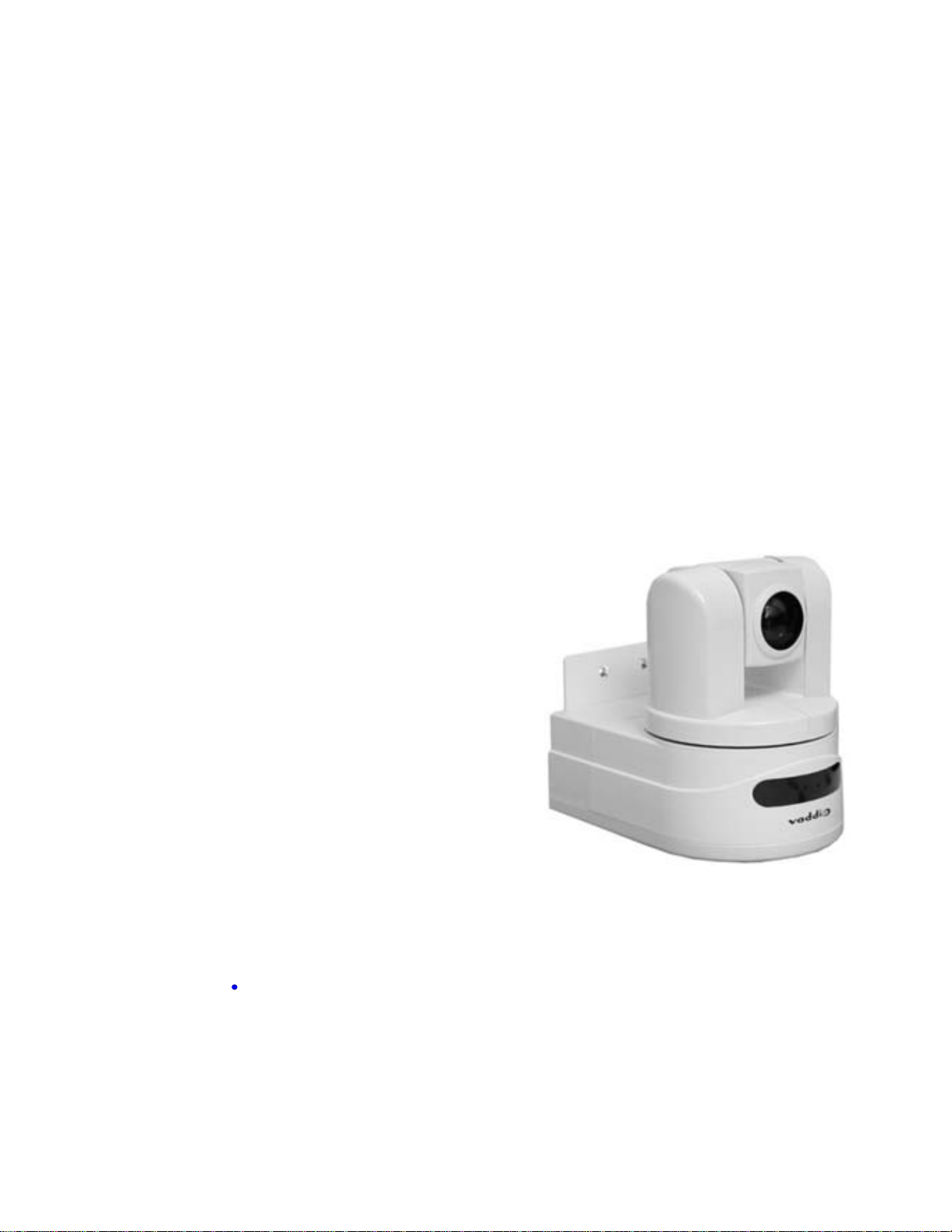
WallVIEW HD-19 PTZ Camera
and CONCEAL Wall Mounting
System
WallVIEW HD-19 DVI/HDMI
WallVIEW HD-19 DVI/HDMI Manual 342-0267 Rev. C Page 4 of 24
UNPACKING:
Carefully remove the device and all of the parts from the packaging.
Unpack and identify the following parts for 999-6946-000:
One (1) ClearVIEW HD-19 HD PTZ Camera
One (1) Vaddio IR Remote Commander
One (1) Quick-Connect DVI/HDMI SR Interface One (1) Laird Technologies 28A2432-0A2 Clamp-on Ferrite Cylinder (Wrap IR forwarding
LED wires twice before screwing stripped wire ends to 3 conductor Molex Euro Jack)
Two (2) Laird Technologies 28A0640-0A2 Clamp-on Ferrite (Clamp around 0.8" diameter DVI Cable at the Quick-Connect DVI end)
One (1) Laird Technologies HFA163090-0A2 Clamp-on Ferrite (Clamp around 0.8" diameter shielded DVI Cable at the Monitor end)
One (1) Vaddio PowerRite™ 24 VDC, 2.0 Amp Power Supply
One (1) 998-1001-232 EZCamera Control Adapter (for control systems)
One (1) 998-1002-232 EZCamera Control Adapter (for TANDBERG VC systems) One (1) 3-pos Phoenix type connector
One (1) CONCEAL Wall Mounting System and Mounting Hardware
One (1) AC Cord Set for North America
Documentation
(Note: The 999-6946-001 Int’l Version includes the Euro and UK power cables)
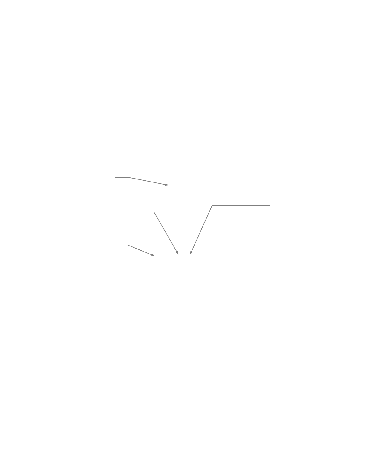
ClearVIEW HD-19 PTZ Camera, Front View with Feature Call-outs:
1) Camera and Zoom Lens:
The 19X optical zoom lens is built around a 1/3-type high-speed CMOS image sensor with a total of 1.3
Megapixels for precise HD video image acquisition.
2) Red Tally Light:
A red tally light is illuminated when the camera receives a VISCA command from an external control system.
3) IR Sensors:
IR sensors are built into the front of the ClearVIEW HD-19 to receive IR signals from the IR remote control
supplied with the camera as well as other 3
rd
party remotes for the IR forwarding feature.
4) Blue Power Light:
A Vaddio blue power light is illuminated when the camera is turned on.
Compatible Vaddio Switchers and Joystick Controllers:
ProductionVIEW™ HD MV
(999-5625-000)
Precision Camera Controller
-
-
AutoPresenter
(999-5675-000)
②
①
③
④
WallVIEW HD-19 DVI/HDMI
WallVIEW HD-19 DVI/HDMI Manual 342-0267 Rev. C Page 5 of 24
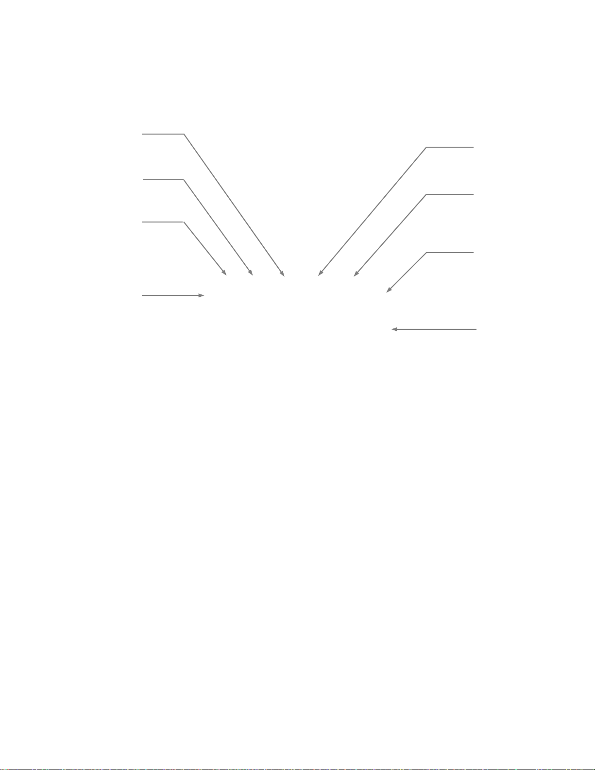
ClearVIEW HD-19 PTZ Camera, Rear View with Feature Call-outs:
5) RS-232 IN & IR Out:
The RS-232 accepts modified VISCA protocol for camera control, as well as transmits IR signaling received by
the IR receivers, which can be transmitted to third party devices.
6) Dip Switch Settings:
Settings for IR remote, baud rate, SD output format, and image flip can be configured on these switches. See
page 5 for additional information on switch settings.
7) HD Video Select:
A rotary switch allows the user to choose the component HD output video resolution and format. See page 6 for
additional information on switch settings.
8) 12 VDC Input:
Power input for the standard, ClearVIEW HD-19 camera power supply.
9) YPbPr Output:
Component HD video is fed through the DB-15 connector. YPbPr and Composite signals are simultaneous. This
is an HD camera and the SD signals are down converted and are really not the sweet spot of this camera.
10) Composite Video (CVBS) Output:
The CVBS output feeds out SD video signals and is configurable with the dip switches to choose between
480i/NTSC or 576i/PAL in 4:3 formats. Squeeze and letterbox modes are also available (see dipswitches 6&7).
11) EZ Power/Video Port:
This RJ-45 connector is only used with the Quick-Connect SR Interface and the Quick- Connect DVI-D/HDMI SR
Interface to supply power and return HSDS video from the camera.
12) Slot for Optional Cards:
Optional slot cards can be plugged into the ClearVIEW HD-19 camera (the HD-SDI Slot Card and the EZIM CCU
Slot Card are available separately).
⑥
⑤
⑧
⑦
⑩
⑨
⑫
⑪

WallVIEW HD-19 DVI/HDMI
WallVIEW HD-19 DVI/HDMI Manual 342-0267 Rev. C Page 6 of 24
Quick-Connect DVI/HDMI - SR Interface I/O Description
1) Blue LED Power Indicator.
2) 24 VDC Power Port: Coax Power Connector, 5.5mm OD x 2.5mm ID, Positive Center.
3) Recessed Color Space Conversion Switch: Toggles between HDMI YCbCr and sRGB (RGBHV) color
space. Change the color space to accommodate either YCbCr or RGBHV monitors.
4) RS-232 Control Input (from joystick controller, codec or control system).
5) To Camera: RS-232 Control to & from Camera and IR signals returned from the camera.
6) Daisy Chain Control Port: Daisy Chain Control Emulation (DCCE) output to next Quick-Connect DVI/HDMI
SR Interface (does not function with the AutoTrak System).
7) IR Output Port: Non-modulated (for hard connections) and Modulated for use with IR emitters.
8) DVI-D Output: High Definition Multimedia Interface (HDMI) Transmitter, HDMI (v 1.3 with deep color) and
DVI v 1.0 Compliant - use Recessed Color Space Conversion Switch to toggle between HDMI YCbCr and
sRGB (RGBHV) color spaces to suit your monitors
9) YPbPr Output: Analog Component Video Output on DE-15F (HD-15F) Connector, Resolutions up to
1080p/60 with monitor support.
10) EZCamera Power & HD Video Port: Supplies power to camera and return s HD video from the camera via
Cat-5e. Maximum distance on the Cat-5e cable is 100’ (30.5 m).
Installation Basics:
The WallVIEW HD-19 product was designed for installation on a vertical wall surface with Cat-5e cable
connectivity for Power, Video and Control signaling (two Cat-5e cables are required). Installation is simplified in
that no custom 8-Pin mini-din cables or expensive coax plenum cables are needed and no power outlets are
required near the camera bracket. All cabling is routed to the head-end using Cat-5e cables.
Before Installing:
Locate the camera mounting location paying close attention to camera viewing angles, lighting conditions,
possible line of site obstructions, and checking for in-wall obstructions where the camera is to be mounted.
Pick a mounting location that will optimize the performance of the camera.
The CONCEAL Wall Mounting System for the WallVIEW HD-19 can be mounted directly to a 2-gang wall box
or can be mounted to the drywall using the supplied four (4) drywall anchors.
RS-232 Cabling:
For RS-232, use a standard Cat-5e cable and RJ-45 connectors (568B termination) from the RS-232 port on the
back of a Vaddio camera controller or switcher. If the camera is connected to a third-party control system (such
as AMX or Crestron), a DB-9 to RJ-45 control adapter cable is supplied. Use of pass-thru type RJ-45
connectors is highly discouraged. The Vaddio Cat-5e wiring standard uses pins 7 and 8 on both the
video and the control Cat-5e cables. The pass-through connectors have proven to provide insufficient
connectivity for these important signals. They are “ok” for voice and data, but not for video and control.
Videoconferencing Codecs and RS-232:
Depending on the codec and RS-232 port used, special DB-9 to RJ-45 adapters may sometimes be required.
Refer to Vaddio’s price list or website for Tech Notes on the WallVIEW HD-19 page on specific diagrams for
wiring the camera to videoconferencing codecs. Any special adapters and configuration information will be noted.
Remember to always power up the cameras before booting up the codec.
①
②
③
④⑤ ⑥
⑦
⑨⑧
⑩
WallVIEW HD-19 DVI/HDMI
WallVIEW HD-19 DVI/HDMI Manual 342-0267 Rev. C Page 7 of 24
First Time Set-up with the HD-19:
The ClearVIEW HD-19 was designed to be exceptionally easy to use and operate. There is documentation at the
back of the manual for pin-outs for all of the connectors on the ClearVIEW HD-19 camera.
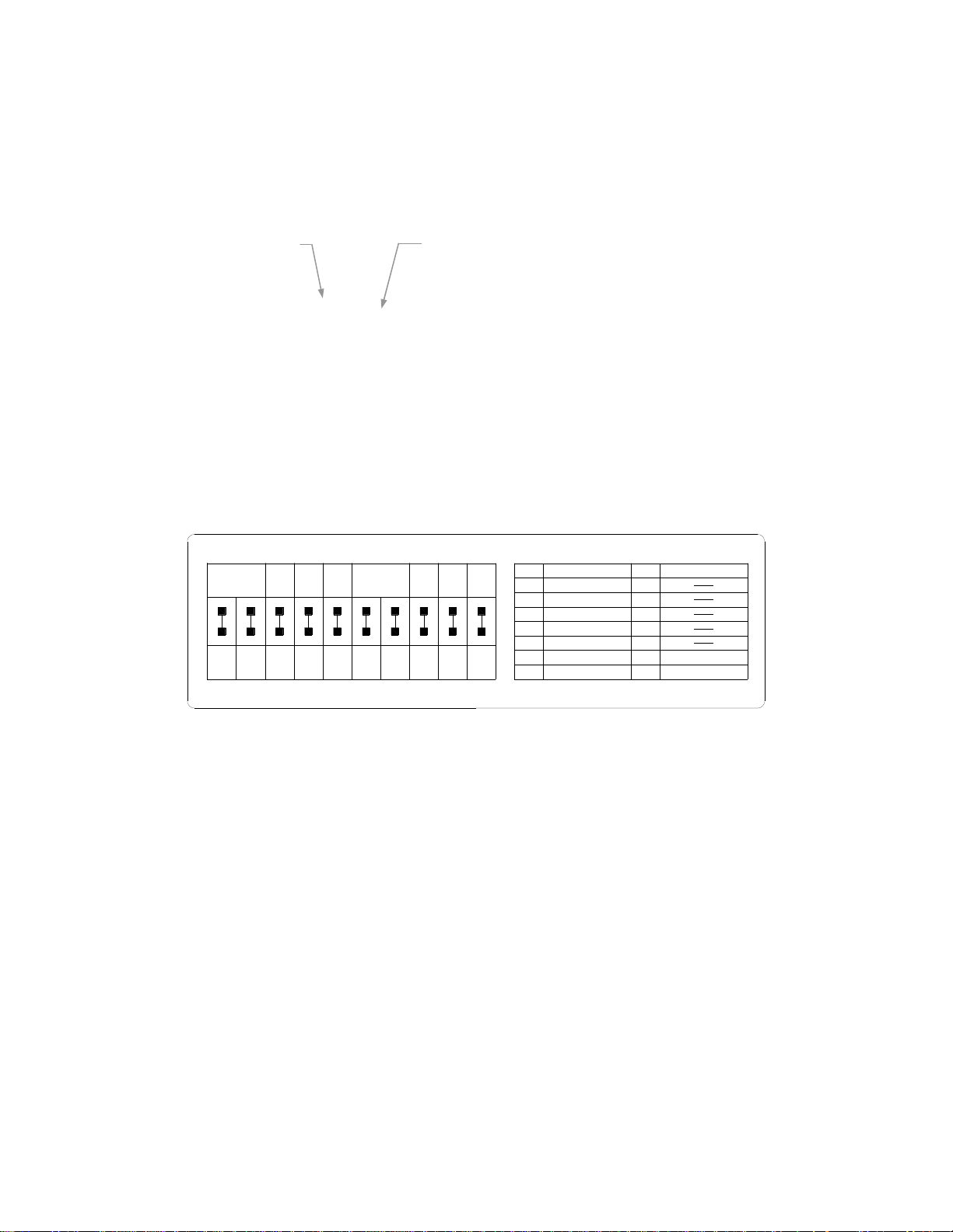
Step 1: Using the HD Video Select Rotary Switch and Camera Settings Dip Switch on the back of the camera,
set up the camera’s output resolution and functional preferences. There is a label on the bottom of the camera
that identifies the choices.
Label on the Bottom of HD-19
Set the HD output resolution for the camera with the Rotary Switch.
Set the IR frequency of the camera if it is to respond to the IR remote control.
If using RS-232 for control, leave the IR OUT OFF (SW3) and choose 9600 bps
If using the IR forwarding feature, turn the IR OUT ON (SW3).
If inverting the camera, turn the IMAGE FLIP ON (SW8).
Dip Switch Settings:
IR 1 & 2: The IR remote has the capability of operating up to three different PTZ cameras from one
remote. Use the selector buttons at the top of the IR remote to select the frequency.
IR Out 3: The IR output is sent out on the RS-232 RJ-45 jack on the back of the camera. Turning on the
IR output will allow IR signals to be transmitted over the Cat-5e cable to the head end. When using RS-
232 control or Vaddio CCU controllers (also via RS-232), turn the IR OUT to OFF.
Baud Rate 4: The options for baud rate are either 9600 bps or 38,400 bps. Default is 9600 bps.
SD Format 5: Choose between NTSC or PAL formats
SD Configurations 6 & 7: SD video can be set to standard 4:3, squeeze mode or letterbox mode.
Image Flip 8: To invert the HD-19, turn the IMAGE FLIP ON (switch down).
Test Bars 9: Turning on the non-standard test bars will override the camera video output. These non-
standard test bars are 75% IRE.
Switch 10: Leave up - or in the OFF position
HD Video Select Switch Camera Settings 10-Pos Dip Switch
HD-19
Rear
Panel
IR 1
1 & 2 UP
ON
SD
NTSC
SD
PAL
SD 4:3
6 & 7 UP
SD
LB
IMAGE
FLIP
OFF
ON ON
DIP SWITCH SETTINGS
8
12
3
4
56
7
910
HD VIDEO SELECT
720p/59.94
1080i/59.94
0
1
2
3
4
5
6
7
8
9
A
B
C
D
E
F
1080p/59.94
1080p/60
720p/50
1080i/50
1080p/50
21
5
4
3
7
68109
ON
IR 2
ON
IR 3
ON
IR
OUT
OFF
9600
bps
38400
bps
SD
SQ
TEST
BARS
OFF
10
OFF
480i/29.97
1080p/25
1080p/30
576i/25
WallVIEW HD-19 DVI/HDMI
WallVIEW HD-19 DVI/HDMI Manual 342-0267 Rev. C Page 8 of 24
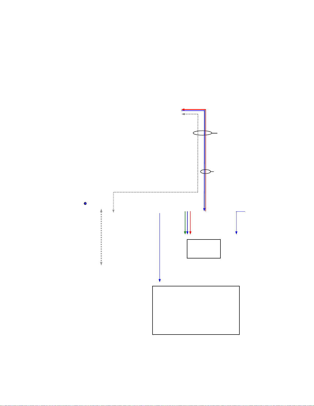
System Connectivity Example 1:
Basic system connectivity of a Vaddio WallVIEW™ DVI/HDMI HD-19 and Quick-Connect DVI/HDMI SR Interface
with Vaddio ProductionVIEW™ Precision Camera Controller and PreVIEW HD Monitors.
WallVIEW DVI/HDMI
HD-19 System
Quick-Connect
DVI/HDMI SR
Interface
Two (2) - Cat-5e Cables
Total - Up to 100’ (30.48m)
RS-232 Control - Cat-5e
Power to Camera
HSDS Video from
Camera - Cat-5e
Vaddio Precision Camera Controller
(Up to 7 PTZ Cameras can be controlled)
R
S
-2
3
2
o
n
Ca
t-
5e
Large Format HDMI Monitor
(Simulated Video Feed)
Vaddio PreVIEW™ HD 7.0 Rack Monitors
(Simulated Video Feeds)
*HDMI with
Adapter Cable
YP
b
P
r
YPbPr & Power on
one (1) Cat-5e up to
100’ (30.5m)
Dancing Bear Camera
(Simulated Feed)
* The Recessed Color Space
Conversion Switch enables the
use of either HDMI YCbCr or
DVI-D sRGB (RGBHV) color
space for added flexibility.
 Loading...