


JSD 100 Manual
Cinema Processor
USL, Inc.
181 Bonetti Drive
San Luis Obispo, CA 93401 7397
USA
Phone: +1 805 549 0161 Fax: +1 805 549 0163 www.uslinc.com
Revised
October 6, 2011
One Year Limited Warranty
USL, Inc. warrants that each product manufactured by it will be free from defects in material and workmanship under normal usage for a period of one (1) year after its purchase new from an authorized dealer. Our obligation under this warranty is limited to repairing or replacing any product or component which we are satisfied does not conform to the foregoing warranty and which is returned to our factory, freight paid, or serviced by one of our authorized contractors. The foregoing warranty is exclusive and in lieu of all other warranties, whether expressed or implied. Such warranty shall not apply to any product or component (A) repaired or altered by anyone other than USL, Inc. or an authorized service contractor; (B) tampered with or altered in any way or subjected to misuse, negligence or accident or (C) which has been improperly connected installed or adjusted other than in accordance with USL, Inc.’s instruction.
2
|
|
Table of Contents |
|
1. |
Safety Notice................................................................................................................................................ |
4 |
|
2. |
Regulatory Compliance ................................................................................................................................ |
4 |
|
|
2.1 |
Declaration of Conformity ................................................................................................................. |
6 |
|
2.2 |
Equipment Class................................................................................................................................ |
7 |
|
2.3 |
Disposal and Recycling ...................................................................................................................... |
7 |
3. |
System Version ............................................................................................................................................ |
7 |
|
4. |
System Overview ......................................................................................................................................... |
7 |
|
|
4.1 |
System Description............................................................................................................................ |
7 |
|
4.2 |
Model Numbers ................................................................................................................................ |
8 |
|
4.3 |
Soundfield Configurations ................................................................................................................. |
9 |
|
4.4 |
Processing Channels ......................................................................................................................... |
10 |
5. |
Specifications............................................................................................................................................. |
10 |
|
6. |
Installation................................................................................................................................................. |
12 |
|
|
6.1 |
Initial Power Up ............................................................................................................................... |
12 |
|
6.2 |
System Hardware Mounting, Grounding and Ventilation .................................................................. |
13 |
|
6.3 |
Eight Channel Analog Output Rear Panel Connections....................................................................... |
13 |
|
6.4 |
Sixteen Channel Analog Output Rear Panel Connections (JSD 100xA)................................................ |
14 |
|
6.5 |
Thirty two Channel AES Output Rear Panel Connections (JSD 100xD)................................................ |
15 |
|
6.6 |
Audio Input Connections .................................................................................................................. |
16 |
|
6.7 |
Analog Audio Output Connections.................................................................................................... |
17 |
|
6.8 |
Automation Interface ....................................................................................................................... |
17 |
7. |
Graphical User Interface Configuration....................................................................................................... |
18 |
|
|
7.1 |
GUI File Organization........................................................................................................................ |
18 |
7.218
|
7.1 |
GUI Installation ................................................................................................................................ |
18 |
|
7.3 |
Set IP Utility ..................................................................................................................................... |
20 |
|
7.4 |
JSD 100 Configuration ...................................................................................................................... |
20 |
|
7.5 |
Crossover Adjustment ...................................................................................................................... |
30 |
|
7.6 |
Equalization Adjustment .................................................................................................................. |
31 |
|
7.7 |
Automation...................................................................................................................................... |
33 |
|
7.8 |
System Monitoring........................................................................................................................... |
34 |
|
7.9 |
GUI View of Multiple JSD 100s.......................................................................................................... |
34 |
8. |
JSD 100 Web Interface ............................................................................................................................... |
35 |
|
9. |
SNMP Monitoring ...................................................................................................................................... |
36 |
|
10. |
Product Support......................................................................................................................................... |
38 |
|
Appendix A – Connector Pin Outs...................................................................................................................... |
39 |
||
JSD 100 Manual Revision History ...................................................................................................................... |
49 |
||
Index ................................................................................................................................................................ |
|
49 |
|
3
1.Safety Notice
Safety Notices
Review the following safety precautions to avoid injury and prevent damage to this product. To avoid potential risk, use this product only as specified and only for the purpose described in the instruction manual.
To Avoid Fire and Personal Injury:
Use correct power cable. Use only the power cable provided. Ensure that the AC power outlet is located near the product and is easily accessible.
Use a correctly grounded power source. The power supply earth ground is established through the ground conductor in the power cable. To avoid the potential of electric shock, the ground conductor must be correct.
Observe source ratings. To avoid risk of fire or electric shock, the power source must be 100 – 240 VAC, 50 – 60 Hz.
Do not operate with suspected failures. If you suspect there is damage or malfunction with this product, call the factory.
Do not attempt repair. Only a trained factory service person is authorized to repair this product.
Do not operate this product near heat sources. This product should not be located near heat sources such as radiators, heat registers, or stoves.
Provide proper ventilation. The operating temperature range is between 0º C and 40º C. The humidity range is between 20% and 80%, non condensing. The cooling method is convection.
Keep product surfaces clean and dry. Disconnect the power cable from the power source before cleaning. Do not use liquid cleaners or aerosol cleaners. Use a damp cloth for cleaning.
Do not push objects into openings of this product. Never insert objects into the product through openings.
Do not operate in wet or damp conditions.
Do not operate in an explosive atmosphere.
Inspect the power cable and all cables prior to use. Confirm that the power cable and other interconnecting cables are free from damage.
2.Regulatory Compliance
EN 60950 1
The EN 60950 1 standard specifies the safety design requirements that reduce or eliminate the risk of personal injury to both the product user and service personnel. This product is designed and tested to meet the standards of the International Electrotechnical Commission (IEC) European Norm EN 60950 1, IEC 60950 1 (the standard for information technology equipment including electrical business equipment).
Le Résumé de la Sécurité general Européen
Examinez les précautions de la sécurité suivantes éviter la blessure et prévenir le dégât à ce produit. Éviter le risque potentiel, utilisez ce produit seulement comme a spécifié et seulement car le but a décrit dans le manuel d’instructions.
Éviter Feu et Blessure Personnelle
Utilisez le Câble du Pouvoir Correct. Utilisezseulement le câble du pouvoir fourni. Assurez que lesAC font fonctionner le débouché est localisé près leproduit et est accessible facilement.
Utilisez une Source du Pouvoir Correctement Fondée.
La terre du monde de la Provision du Pouvoir estétablie à travers le conducteur moulu dans le câble du pouvoir. Éviter le potentiel de choc électrique, leconducteur moulu doit être correct.
Observez des Estimations de la Source. Pour éviterrisque de feu ou choc électrique, la source du pouvoirdoit être 220 240 VAC 50 Hz.
N’opérez pas ce Produit avec Toutes Clôtures Ouvertes ou Enlevez.
Évitez l’Ensemble de circuits Exposé. N’entreprenez pas ouvrir la Provision du Pouvoir parce que sa certi fication de la sécurité serait invalidée. La Provision du Pouvoir est un appareil scellé non réparable.
4
N’opérez pas avec les Échecs Suspects. Si vous suspectez il y a le dégât ou mal fonctionner avec ce produit, appelez l’usine.
N’entreprenez pas Réparation. Seulement une personne du service de l’usine compétente est autorisée pour réparer ce produit.
N’opérez pas ce Produit Sources de la ChaleurProches. Ce produit ne devrait pas être localisé desources de la chaleur proches tel que radiateurs, registres de la chaleur, poêles, ou amplificateurs.
Fournissez Ventilation Adéquate. La température dufonctionnement devrait être entre 0° C et 40° C.
L’humidité devrait être 20% et 80%. La méthoderefroidissante est par convection et un ventilateur interne.
Gardez les Surfaces du Produit Nettoient et Sec.
Déconnectez le câble du pouvoir de la source du pouvoir avant de nettoyer. N’utilisez pas de nettoyeurs. liquides ou de nettoyeurs de l’aérosol Utilisez un tissu humide pour nettoyer.
Ne poussez pas d’Objets Dans Ouvrir de ce Produit.
Jamais objets de l’encart dans le produit à travers ouvertures.
N’opérez pas Dans les Conditions Mouillées ou humides.
N’opérez pas Dans une Atmosphère Explosive.
Prévenez le Répandre des Liquides sur les Composants du Système.
Inspectez le câble du pouvoir et tous les câbles antérieur à usage. Confirmez que le câble du pouvoir et autres interconnectant câbles sont libres de dégât.
Le Niveau de la sécurité
L’EN 60065 niveau spécifie exigences du dessin de la sécurité qui réduisent ou éliminent le risque de blessure personnelle à l’utilisateur du produit et personnel du service. Ce produit est conçu et est testé pour satisfaire aux niveaux de l’Electrotechnical Commission Interna tional (IEC) Norm Européen (EN) 60065 (Le Niveau pour Matériel de la Technologie de l’Information qui Inclut le Matériel de l’Affaire Électrique).
Allgemeine Sicherheit Zusammenfassung Europäisch
Überprüfen Sie die folgend Sicherheit Vorkehrungen, Verletzung zu vermeiden und Schaden zu diesem Produkt zu verhindern. Um potentielles Risiko zu vermeiden, benutzen Sie dieses Produkt nur als vorgeschrieben hat und nur denn der Zweck beschrieb in der Bedienungsanleitung.
Um Feuer und Persönliche Verletzung zu vermeiden:
Benutzen Sie Korrektes Macht Kabel. Benutzen Sie nur das Macht Kabel, das bereitgestellt wurde. Stellen Sie sicher, daß der WECHSELSTROM Macht Abfluß in der Nähe vom Produkt gefundenwird und leicht zugänglich ist.
Benutzen Sie eine Korrekt geerdet Macht Quelle. Der Macht Versorgung Erde Boden wird durch den Boden Schaffner im Macht Kabel gegründet. Das Po tential elektrischen Schocks zu vermeiden muß der Boden Schaffner korrekt sein.
Beobachten Sie Quelle Klassen. Risiko von Feuer oder elektrischem Schock zu vermeiden muß de Macht Quelle 100 sein 240 VAC 50 60 Hz.
Operieren Sie dieses Produkt mit Irgendwelchen Gehegen nicht, die geöffnet wurden, oder entfernen Sie.
Vermeiden Sie Ungeschützten Schaltkreise. Versuchen Sie, die Macht Versorgung zu öffnen nicht, weil seine Sicherheit Zulassung ungültig gemacht werden würde. Die Macht Versorgung ist ein nicht reparierbares luftdicht verschlossene Gerät.
Operieren Sie mit verdächtigt Mißerfolgen nicht.Wenn Sie verdächtigen, gibt es Schaden oder Funktionsstörung mit diesem Produkt, rufen Sie die Fabrik.
Versuchen Sie keine Reparatur. Nur eine erzogen Fabrik Dienst Person wird ermächtigt, dieses Produkt zu reparieren.
Operieren Sie dieses Produkt Nahe Hitze Quellen nicht. Dieses Produkt sollte keine nahe Hitze Quellen wie Heizkörper, Hitze Register, Herde, oder Verstärker gefunden werden.
Stellen Sie Richtige Belüftung bereit. Die operierend Temperatur sollte zwischen 0° C und 40° C. Die Luftfeuchtigkeit sollte sein 20% und 80%. Die erfrischend Methode ist durch Konvektion und einen innereren Fächer.
5
Bleiben Sie, Produkt Oberflächen reinigen und Trocken. Trennen Sie das Macht Kabel von der Macht Quelle vor dem Reinigen. Benutzen Sie keine flüssige Reiniger oder Aerosol Reiniger. Benutzen Sie einen klammen Stoff für das Reinigen.
Schieben Sie keine Gegenstände Ins Öffnen von diesem Produkt. Nie Beifügung Gegenstände ins Produkt durch Öffnungen.
Operieren Sie In Nassen oder Klammen Zuständen nicht.
Operieren Sie In einer Explosiven Atmosphäre nicht.
Verhindern Sie das Verschütten von Flüssigkeiten auf die System Bestandteile.
Inspizieren Sie das Macht Kabel und alle Kabel vorausgehend zu Verwendung. Bestätigen Sie, daß das Macht Kabel und andere verbindend Kabel frei von Schaden sind.
Sicherheit Standard
Der EN 60065 Standard schreibt Sicherheit Entwurf Anforderungenvor, der reduzieren oder das Risiko persönlicher Verletzung zu sowohl dem Produkt Benutzer als auch Dienst Personal ausschließen. Dieses Produkt wird entworfen und wird geprüft, um den Standards vom Internationalen Electrotechnical Commission zu entsprechen (IEC) europäischer Norm (EN) 60065 (Der Standard für Informationen Technologie Ausrüstung, die Elektrische Unternehmen Ausrüstung einschließt).
2.1Declaration of Conformity
The JSD 100 meets the intent of Directive 89/336/EEC for Electromagnetic Compatibility and Low Voltage Directive 73/23/EEC for Product Safety. Compliance was demonstrated to the following specifications as listed in the Official Journal of the European Communities:
EN 55022: 2006 Conducted and Radiated Emissions
Conducted Emissions
Radiated Emissions, Class A Limits
EN 55024: 1998 + A1: 2001 & A2: 2003 Immunity
Electrostatic Discharge Immunity
RF Electromagnetic Field Immunity
Power Line Surge Immunity
Conducted RF immunity
Power Frequency Magnetic Field Susceptibility
Voltage Dips, Short Interruptions and Variations
EN 61000 3 3: 1995 +A1: 2001 & A2: 2005 Voltage Fluctuation and Flicker
FCC Part 15, Subpart B
This equipment has been tested and found to comply with the limits for a Class A digital device, pursuant to part 15 of the FCC Rules. These limits are designed to provide reasonable protection against harmful interference when the equipment is operated in a commercial environment. This equipment generates, uses, and can radiate radio frequency energy and, if not installed and used in accordance with the instruction manual, may cause harmful interference to radio communications. Operation of this equipment in a residential area is likely to cause harmful interference in which case the user will be required to correct the interference at user’s own expense.
Certifications
Low Voltage Directive 73/23/EEC.
EN 60950 Information Technology, Video, and similar Electronic Apparatus.
IEC 60950 Safety Requirements.
CE, UL, cUL Safety and Overall Compliance.
VDE Certified Power Cords.
Pollution: Not intended for environments where conductive pollutants may be present.
6

2.2Equipment Class
Type A: Equipment that is intended for connection to the building power supply wiring via nonindustrial plugs and sockets or via appliance couplers, or both.
2.3 Disposal and Recycling Wheelie Bin Symbol
The Wheelie Bin symbol is attached to this product in compliance with the EU Directive 2002/96/EC on Waste Electrical and Electronic Equipment (WEEE). Its purpose is to deter the improper disposal of this product and to promote reuse and recycling.
Proper Disposal
In conformance with the Directive, at end of life this product should be either sent to an appropriate recycling facility for disassembly and recycling or returned to the supplier. Under no circumstances should this product be deposited in a landfill for disposal.
Hazards of Noncompliance
Electrical and electronic products may contain chemicals which can leach into the groundwater and cause health concerns through contaminated drinking water. Failure to dispose of this product in compliance with the WEEE Directive may result in penalties as determined by local ordinance.
Please contact your dealer or USL, Inc., with questions regarding the proper disposal of this or any other USL product. USL, Inc. contact information: USL, Inc., 181 Bonetti Drive, San Luis Obispo, CA 93401 7397, USA. Phone: +1 805 549 0161 Fax: +1 805 549 0163 www.uslinc.com
3.System Version
The JSD 100 is continuously being improved. New features are added through software/firmware updates and replacement of plug in modules. This manual describes the JSD 100 versions available at this writing.
Firmware/software versions for the systems described in this manual are listed in the table below:
Component |
Version |
|
Graphical User Interface (GUI) |
2.3.5.27222 |
|
Main PIC |
110929 |
|
DSP 1 |
|
1110819 |
DSP 2 |
|
2110819 |
4. |
System Overview |
|
4.1System Description
The JSD 100 cinema sound processor is specially designed for digital cinema applications. Low noise and low distortion 96 kHz processing ensures superb presentations. In addition to the eight standard formats, the JSD 100 offers two fully configurable formats. The two user configurable buttons can be configured to support a variety of existing and future formats. They may also be used to duplicate an existing format but at a different fader level to simplify desired volume changes between content types. The front panel display shows the current fader level, the format name (which is user configurable), and the measured audio level on each channel of the main audio output. The built in bypass audio circuitry insures that the presentation goes on in the unlikely event of a system failure.
The JSD 100 is “automation friendly.” It features the standard DB25 parallel automation interface, an RS 232 (EIA232) interface, and Ethernet. The Ethernet interface accepts 5 simultaneous TCP connections to allow control by a digital cinema server and other equipment while simultaneously being monitored over another TCP connection.
7

The Graphical User Interface runs on Windows XP® and Windows 7® operating systems. It allows for complete system configuration, monitoring, and firmware updates over USB, Ethernet, or RS 232. System monitoring, control, and firmware update functions are also available on a standard web browser.
The JSD 100 is also “diagnostic friendly.” The system logs the last 32,000 events (format changes, level changes, internal temperature, loss of AES audio, etc.) to internal flash memory. Log data can be reviewed on the GUI or the web interface. Current operational status, including selected format, fader level, and measured audio output levels, is available on the GUI and on the web interface. The current status of the system is also available over SNMP (Simple Network Management Protocol).
A plug in module expands the standard 8 channel digital input (4 AES pairs) to a 16 channel digital input (8 AES pairs). Another plug in module decodes Dolby® Digital 1 on alternate content inputs.
The HI and VI N outputs are configurable on a per format basis. Rear panel output modules are available to output eight or sixteen analog signals (servo balanced outputs that can drive balanced or unbalanced loads), or 32 AES channels (16 AES pairs). The model number (described below) determines which output module is installed.
4.2Model Numbers
The output module is field replaceable to allow a variety of output configurations. Available output configurations include 8 analog outputs, 16 analog outputs, or 32 channels of AES/EBU audio. When more than 8 outputs are available, the outputs can be used for additional auditorium channels (such as 13.1), or as outputs for the internal crossovers.
The various JSD 100 options are identified by model number suffixes as shown in the tables below. The first letter identifies input options, such as the number of AES inputs or decode options. The second letter indicates the number and type of outputs, such as whether they are analog or AES. Note that all units also have analog HI/VI N outputs in addition to the outputs listed in the tables below.
First Suffix Letter |
Description |
USL Module Part Number |
L |
8 channel AES input, no Dolby Digital® decode |
N/A |
D |
8 channel AES input, Dolby Digital® decode on alternate content |
DI 84 |
M |
16 channel AES input, Dolby Digital® decode on alternate content |
DI 80 & DI 84 |
|
|
|
Second Suffix |
Description |
USL Module Part Number |
Letter |
|
|
None |
8 channel analog output |
JSDR 100 |
A |
16 channel analog output (full range 13.1 channels, biamp 5 |
JSDR 123 |
|
screen channels, triamp 3 screen channels) |
|
D |
32 channel AES output (full range 13.1 channels, biamp or triamp |
JSDR 110 |
|
5 screen channels) |
|
A JSD 100MA has 16 AES input channels, Dolby Digital® and decoding for alternate content and 16 analog outputs. In the transition to digital cinema, the industry is adopting new names and abbreviations for speaker locations. Generally, the first letter is capitalized and either L for left, C for center or R for right. The second and third letters, if present, are lower case and further define the position.
1 Manufactured under license from Dolby Laboratories. Dolby and the double D symbol are trademarks of Dolby Laboratories.
8
New Name |
Description |
Previous Name |
(abbreviation) |
|
(abbreviation) |
Left (L) |
Typically positioned behind the screen to the far left edge, horizontally, |
Left (L) |
|
of the screen center as viewed from the seating area. |
|
Right (R) |
Typically positioned behind the screen to the far right edge, |
Right (R) |
|
horizontally, of the screen center as viewed from the seating area. |
|
Center (C) |
This loudspeaker position is typically behind the screen corresponding |
Center (C) |
|
to the horizontal center of the screen as viewed from the seating area. |
|
|
Also the intended speaker position for mono reproduction |
|
Low Frequency |
Screen low frequency effects subwoofer loudspeaker(s). This is typically |
Subwoofer (SW) |
Effects (LFE) |
one or more band limited low frequency only loudspeakers at the |
|
|
screen end of the room. |
|
Left surround |
Typically an array of loudspeakers positioned along the left side of the |
Left Surround (LS) |
(Ls) |
room starting approximately 1/3 of the distance from the screen to the |
|
|
back wall and the left side of the rear wall. Left surround may not |
|
|
extend to the back wall of the auditorium in some soundfield |
|
|
configurations, particularly when Left rear surround is present. |
|
Right surround |
Typically an array of loudspeakers positioned along the right side of the |
Right Surround |
(Rs) |
room starting approximately 1/3 of the distance from the screen to the |
(RS) |
|
back wall and the right side of the rear wall. Right surround may not |
|
|
extend to the back of the auditorium in some soundfield configurations, |
|
|
particularly when Right rear surround is present. |
|
Left rear |
One or more loudspeakers typically on the back wall of the room to the |
Back Surround Left |
surround (Lrs) |
left horizontally. |
(BSL) |
Right rear |
One or more loudspeakers typically on the back wall of the room to the |
Back Surround |
surround (Rrs) |
right horizontally. |
Right (BSR) |
Left center (Lc) |
Mid left to center screen loudspeaker. This loudspeaker position is |
Left Center (LC) |
|
typically between the center of the screen and the left edge of the |
|
|
screen, usually closer to the left. |
|
Right center |
Mid right to center screen loudspeaker. This loudspeaker position is |
Right Center (RC) |
(Rc) |
typically between the center of the screen and the right edge of the |
|
|
screen, usually closer to the right. |
|
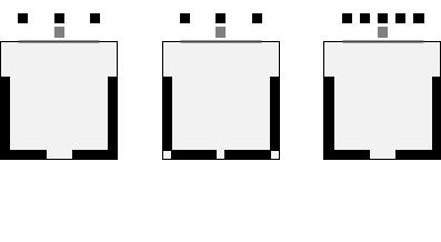
4.3Soundfield Configurations
The standard soundfield configurations (or speaker configurations) as defined by SMPTE are shown in the diagram below. Note there are two defined 7.1 configurations. One (7.1DS) has rear surround speakers, while the other (7.1SDDS) extends the side surround speakers to the rear wall and adds left center and right center speakers.
9

The JSD 100 is configured for the particular speaker configuration in the auditorium. Each format is then configured as to how the speakers in that auditorium are driven. For example, when an auditorium is configured for 7.1DS, which includes rear surround speakers, and 5.1 content is played, the rear surround speakers can be driven by the surround channels, or a mix of the surround channels.
4.4Processing Channels
The JSD 100 has 14 “processing channels.” Each of these receives audio from a variety of sources. The “processing channel” includes the main fader control, equalization, synchronization or input delay, surround delay (on the surround channels), and, as an option, crossovers on the screen channels. Outputs on the rear panel are identified by the channel usage (i.e., L for left). The table below describes the processing channels, their inputs, and how their outputs are identified on the rear panel. Two channel inputs (COAX1, COAX2, TOSLINK, NON/SYNC, and AUX) are identified as “stereo” inputs. If the USL DI 84 card is installed (first suffix of the model number is D or M), stereo inputs can be decoded to several other channels. Without the DI 84 card, stereo inputs can drive left and right directly or left, center, and right with the center being derived from left and right or can drive screen and surround speakers using a “simple matrix.” These are identified as “decoded stereo” in the table below. The rear surround channels may be driven by several AES sources plus a rear surround derived from the side surround signals. When derived from side surrounds, the input is identified as “decoded 5.1.”
Inputs |
|
Processing Channel |
|
Output Panel Identifier |
AES 1, Analog 1, Stereo, Mic |
Left |
|
L |
|
AES 2, Analog 2, Stereo, Mic |
Right |
|
R |
|
AES 3, Analog 3, Decoded Stereo, Mic |
Center |
|
C |
|
AES 4, Analog 4, Stereo, Mic |
Low Frequency Effects |
|
LFE |
|
AES 7, Analog 7, Derived (L and C) |
Left center |
|
Lc |
|
AES 8, Analog 8, Derived (R and C) |
Right center |
|
Rc |
|
AES 5, Analog 5, Decoded Stereo, Mic |
Left surround |
|
Ls |
|
AES 6, Analog 6, Decoded Stereo, Mic |
Right surround |
|
Rs |
|
Ls, AES 7, AES 11, Decoded 5.1 |
Left rear surround |
|
Lrs |
|
Rs, AES 8, AES 12, Decoded 5.1 |
Right rear surround |
|
Rrs |
|
AES 9 |
|
Unassigned |
|
CH9 |
AES 10 |
|
Unassigned |
|
CH10 |
AES 13 |
|
Unassigned |
|
CH13 |
AES 14 |
|
Unassigned |
|
CH14 |
5. |
Specifications |
|
|
|
Features
A processor specially designed for Digital Cinema applications. Low noise and low distortion processing ensures superb presentations. In addition to eight standard formats, the JSD 100 offers two fully configurable optional formats to address such details as audio level changes and 3 or 5 stage channels. Built in bypass audio circuitry ensures that the presentation goes on.
Audio Inputs
PA Microphone – XLR 0.7mV sensitivity.
Calibration Microphone – 3.5mm stereo jack 0.7mV sensitivity with 10V power.
Non Sync analog input – RCA 75mV to 4.775V.
Auxiliary analog input – RCA 300mV.
Eight Channel analog input – DB25F 300mV.
COAX1 – RCA PCM and optional Dolby Digital® decoding.
COAX2 – RCA PCM and optional Dolby Digital® decoding.
TOSLINK – Optical PCM and optional Dolby Digital® decoding.
AES EBU 8 Channel 48 96KHz sample rates (16 channel with DI 80 optional card).
10
Analog Audio Outputs – Accessibility
Hearing Impaired – User selectable input channel or LCR mix. 300mV mono balanced.
Visual Narration – User selectable input channel (8 or 16). 300 mV mono balanced.
Eight Channel Analog Audio Output (JSD 100x)
Eight Channels Balanced 300mV adjustable (L, C, R, Ls, Rs, LFE, Lc/Lrs, Rc/Rrs).
Sixteen Channel Analog Audio Output (JSD 100xA)
Sixteen Channels Balanced 300mV adjustable. Configurable as 5.1, 7.1 broadband, biamp three or five screen channels, triamp three screen channels or 13.1
Thirty two Channel AES Output (JSD 100xD)
Thirty two audio channels on 16 AES pairs. Configurable as 5.1, 7.1, or 13.1 broadband, biamp or triamp five screen channels.
Communication Ports
DB25F pulse automation.
Serial control – RS 232.
USB for laptop setup.
Ethernet 10/100 RJ45.
Front Panel Interface
Eleven buttons: COAX1, COAX2, TOSLINK, DIGITAL 16 CH, USER 1, USER 2, ANALOG 8 CH, NON/SYNC, AUX, MIC, and MUTE.
Main Fader – 0 10 used for main audio and bypass audio.
Front panel displays fader level and selected format. Bar graphs display output levels.
USB connector.
Power switch and power supply status LEDs. Turning power off activates bypass mode.
Format Selection
Digital (COAX1, COAX2, TOSLINK, 8 to 16 Channel AES EBU).
Analog (8 channel, Non Sync, Auxiliary, Microphone).
User 1, User 2 (Configurable in software, e.g., digital 16 channel at lower level, 7.1, 13.1, etc.).
Rear Panel Connectors – Main Chassis
PA Microphone – XLR / ¼” phone jack.
Calibration Microphone – 3.5mm stereo jack.
Eight Channel Analog – DB25F.
Non/Sync – two RCA jacks.
AUX – two RCA jacks.
Hearing Impaired and Visual Narration – pluggable Phoenix connector.
COAX1 and COAX2 – RCA Jacks with transformer input
TOSLINK – Optical.
16 Channel Digital AES EBU – DB25 and Dual RJ45.
Removable Memory Card – SD compatible.
Serial Control – RS 232 on DE9F.
Pulse Automation – DB25F.
10/100M Ethernet – RJ45.
DC 12V Power Connector – 5mm with 2.5mm pin.
AC Power – IEC socket. 100 240VAC, 50/60Hz, 18W typical, 7.5W sleep.
11
Rear Panel Interface Module
All rear panel interface modules include an RJ style connector for “USL Link.” This IEEE 485 bus is used for remote volume controls and other control functions. The analog rear panel modules use an RJ25 connector for USL Link. The AES module uses an RJ45 for USL Link and other signals.
JSD 100x (no second suffix letter) – Eight channel analog, one DB25M and one Phoenix connector (20 pins).
JSD 100xA – 16 channel analog output module – Two DB25M and two Phoenix connectors. Outputs configurable as crossover outputs or additional channels.
JSD 100xD – AES/EBU digital output module 32 output channels on 16 AES pairs (4 RJ45 connectors).
Processing
96 kHz processing.
One third octave equalization on all channels except LFE, HI, and VI N.
Parametric equalizers on LFE.
Synchronization delays for all inputs.
Surround delays for all surround channels.
Internal crossovers on systems with 16 or more outputs. Crossovers support biamp and triamp of up to five screen channels plus individual parametric equalization on one to three LFE outputs. Crossover includes a speaker library and allows for user defined speaker systems.
Sleep Mode
With an Ethernet command or preset timeout, the unit can go into a sleep mode. Another Ethernet command, “button press,” or automation pulse will wake up the unit.
Bypass Mode
In an emergency situation, the JSD 100 can be switched off, automatically enabling the bypass circuitry. Front panel buttons, LEDs and fader will still function, allowing the operation of the unit in various analog and digital formats. Final output is a monophonic signal feed to the left and right channels. The AES output module provides a single balanced analog audio output for bypass. Note: The 12 VDC bypass supply must be connected for this functionality.
Dynamic Range: Typically 105dB.
Power Requirements: 100 240VAC, 50/60Hz, 30 watts maximum (18 watts typical, 7.5 watts sleep). Dimensions: Standard 2U rack mount chassis.
Agency Approvals: UL, cUL, CE and FCC.
6.Installation
6.1Initial Power Up
A quick power up test of the JSD 100 is suggested before mounting it in the equipment rack and wiring it up. This test can quickly detect shipping or other damage.
Turn the AC power switch to the off position.
Using the supplied AC line cord or one appropriate for the installation location (the power supply is a universal input supply 100 240 VAC, 50/60 Hz), connect the JSD 100 to the AC line.
Connect the supplied 12 VDC bypass power supply to the bypass power input on the rear panel of the JSD 100 and plug it in to the AC line. The front panel “Bypass Mode” LED should flash, the bypass power LED should light, and one of the format buttons should light.
Press each of the format buttons and the mute button, one after another. The appropriate button should light.
Turn on the AC power switch. The display should immediately light, but be blank. All the green power LEDs on the bottom right of the front panel should light. The “Bypass Mode” LED should stop flashing.
12
After approximately 25 seconds, the format buttons will flash and then a single format LED will light. The display should show the fader level and the selected format.
Press each of the format buttons, verifying that the corresponding LED lights and that the display changes accordingly. Note that the format button LEDs for digital formats will flash when no digital input is provided.
Press the mute button verifying that its LED toggles each time the button is pressed.
Rotate the fader in each direction verifying that the fader numbers on the display change.
6.2System Hardware Mounting, Grounding and Ventilation
The JSD 100 is designed to mount in a standard 19 inch (482.6mm) rack and is two rack units high (3.5 inches, 137.8mm). The JSD 100 should be mounted at “eye level” in the equipment rack for optimum display contrast and visibility. We recommend vented panels (USL part number VP 1) above and below the JSD 100 whenever space permits. Mounting the unit immediately above a major heat producing component, such as a power amplifier, is not recommended. Equipment mounted immediately above the JSD 100 should not be more than 9 inches (225mm) deep to insure adequate airflow through the rear ventilation slots on the JSD 100. The JSD 100 includes a three prong grounding plug and a three wire power cord to accommodate a safe ground path from the chassis to the electrical system ground. Defeating this ground by removing the ground prong is not recommended.
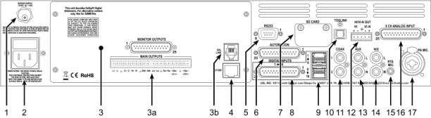
6.3Eight Channel Analog Output Rear Panel Connections
A set of clip on ferrite “beads” is supplied with the JSD 100. To insure the JSD 100 continues to meet FCC and CE radio emissions requirements, one of these beads should be clipped around each cable connected to the rear panel of the JSD 100 except for the TOSLINK, AC Power, and Bypass Power connection.
1.Bypass Power Supply – 12VDC at 1.25A.
2.Power entry Module – Accepts IEC type line cord from 100 240VAC power source. Also contains a 500mA Slo Blo 5x20mm fuse.
3.Eight Channel Analog Output Module – Other modules include 16 channel analog and 32 channel AES.
a.8 Channel Analog Module provides six fixed outputs (L, C, R, LFE, Ls, Rs) and two that can be set up as either Lc/Rc or Lrs/Rrs. Balanced line Phoenix and DB25M connectors are provided. The Phoenix connector normally drives auditorium amplifiers and the DB25M connector normally drives a booth monitor.
b.USL Link An RJ25 connector that provides an RS 485 interface for remote volume control and other functions.
4.Ethernet – Network communications with GUI, web browsers, automation, etc.
5.RS 232 on a DE9F connector for communications with GUI or automation.
6.Automation DB25F Connector – A bidirectional port for receiving and sending automation pulses between the JSD 100 and other system components. 12 Control lines, 11 Status lines and +5V are provided. Standard pulse to ground system.
7.SD Card – Stores a backup copy of unit configuration. Can also be used to transfer settings to another unit.
8.AES connector (DB25F) – Channels 1 8 are standard. Channels 9 16 require the optional DI 80 module.
9.AES connectors (Dual RJ45s) – parallel connections to the DB25F above.
13
10.TOSLINK Port – Optical Fiber input for SPDIF (PCM) or optional Dolby Digital® 2 decoding.
11.COAX 1, COAX 2 RCA type connectors for SPDIF (PCM) or optional Dolby Digital® decoding.
12.Hearing Impaired/Visual Narration Outputs.
13.AUX connectors – L and R analog inputs, 300mV sensitivity.
14.Non Sync (N/S) connectors – L and R analog inputs.
15.RTA microphone – 3.5mm stereo jack with +10V on the ring, designed for use with a powered electret microphone.
16.8 Channel Analog Input on DB25F – Balanced line inputs. Six channels are fixed (L, C, R, LFE, Ls, Rs) and two can be set up as either Lc/Rc or Lrs/Rrs.
17.Public Address Microphone – Dual connector with XLR and ¼” phone jack in the center.
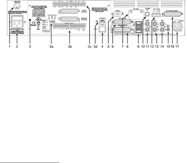
6.4Sixteen Channel Analog Output Rear Panel Connections (JSD 100xA)
A set of clip on ferrite “beads” is supplied with the JSD 100. To insure the JSD 100 continues to meet FCC and CE radio emissions requirements, one of these beads should be clipped around each cable connected to the rear panel of the JSD 100 except for the TOSLINK, AC Power, and Bypass Power connection.
1.Bypass Power Supply – 12VDC at 1.25A.
2.Power entry Module – Accepts IEC type line cord from 100 240VAC power source. Also contains a 500mA Slo Blo 5x20mm fuse.
3.Sixteen Channel Analog Output Module – Other modules include 8 channel analog and 32 channel AES.
a.Bypass crossover adjustments.
b.Main outputs cover the first 8 output channels. The Phoenix connectors normally drive the power amplifiers, and the DB25M connectors drive the booth monitor.
c.Extra outputs cover the second 8 output channels.
d.USL Link An RJ25 connector that provides an RS 485 interface for remote volume control and other functions.
4.Ethernet – Network communications with GUI, web browsers, automation, etc.
5.RS 232 on a DE9F connector for communications with GUI or automation.
6.Automation DB25F Connector – A bidirectional port for receiving and sending automation pulses between the JSD 100 and other system components. 12 Control lines, 11 Status lines and +5V are provided. Standard pulse to ground system.
7.SD Card Stores a backup copy of unit configuration. Can also be used to transfer settings to another.
8.AES connector (DB25F) – Channels 1 8 are standard. Channels 9 16 require the optional DI 80 module.
9.AES connectors (Dual RJ45s) – parallel connections to the DB25F above.
10.TOSLINK Port – Optical Fiber input for SPDIF (PCM) or optional Dolby Digital® 3 decoding.
11.COAX 1, COAX 2 RCA type connectors for SPDIF (PCM) or optional Dolby Digital® decoding.
12.Hearing Impaired/Visual Narration Outputs.
2Manufactured under license from Dolby Laboratories. Dolby and the double D symbol are trademarks of Dolby Laboratories.
3Manufactured under license from Dolby Laboratories. Dolby and the double D symbol are trademarks of Dolby Laboratories.
14

13.AUX connectors – L and R analog inputs, 300mV sensitivity.
14.Non Sync (N/S) connectors – L and R analog inputs.
15.RTA microphone – 3.5mm stereo jack with +10V on the ring, designed for use with a powered electret microphone.
16.8 Channel Analog Input on DB25F – Balanced line inputs. Six channels are fixed (L, C, R, LFE, Ls, Rs) and two can be set up as either Lc/Rc or Lrs/Rrs.
17.Public Address Microphone – Dual connector with XLR and ¼” phone jack in the center.
6.5Thirty two Channel AES Output Rear Panel Connections (JSD 100xD)
A set of clip on ferrite “beads” is supplied with the JSD 100. To insure the JSD 100 continues to meet FCC and CE radio emissions requirements, one of these beads should be clipped around each cable connected to the rear panel of the JSD 100 except for the TOSLINK, AC Power, and Bypass Power connection.
1.Bypass Power Supply – 12VDC at 1.25A.
2.Power entry Module – Accepts IEC type line cord from 100 240VAC power source. Also contains a 500mA Slo Blo 5x20mm fuse.
3.Thirty two Channel AES Output Module – Other modules include 8 and 16 channel analog.
a.Control/Monitor Connector – USL Link for remote volume and other functions plus amplifier monitor return and remote AES input. Monitor return is a future feature.
b.Output channels 1 through 8 on four AES pairs.
c.Output channels 9 through 16 on four AES pairs.
d.Output channels 17 through 24 on four AES pairs.
e.Output channels 25 through 32 on four AES pairs.
f.Monitor and Bypass analog outputs. Monitor output not yet supported.
4.Ethernet – Network communications with GUI, web browsers, automation, etc.
5.RS 232 on DE9F connector for communications with GUI or automation.
6.Automation DB25F Connector – A bidirectional port for receiving and sending automation pulses between the JSD 100 and other system components. 12 Control lines, 11 Status lines and +5V are provided. Standard pulse to ground system.
7.SD Card stores the settings of the unit. Can also be used to transfer settings to another unit.
8.AES connector (DB25F) – Channels 1 8 are standard. Channels 9 16 require the optional DI 80 module.
9.AES connectors (Dual RJ45s) – parallel connections to the DB25 above.
10.TOSLINK Port – Optical Fiber input for SPDIF (PCM) or optional Dolby Digital® 4 decoding.
11.COAX 1, COAX 2 RCA type connectors for SPDIF (PCM) or optional Dolby Digital® decoding. COAX2 input is not supported with the 32 channel JSDR 110 board. Instead, the COAX2 input becomes an AES input on the Control/Monitor connector (3a, above).
12.Hearing Impaired/Visual Narration Outputs.
13.AUX connectors – L and R analog inputs, 300mV sensitivity.
4 Manufactured under license from Dolby Laboratories. Dolby and the double D symbol are trademarks of Dolby Laboratories.
15
 Loading...