


6041HF
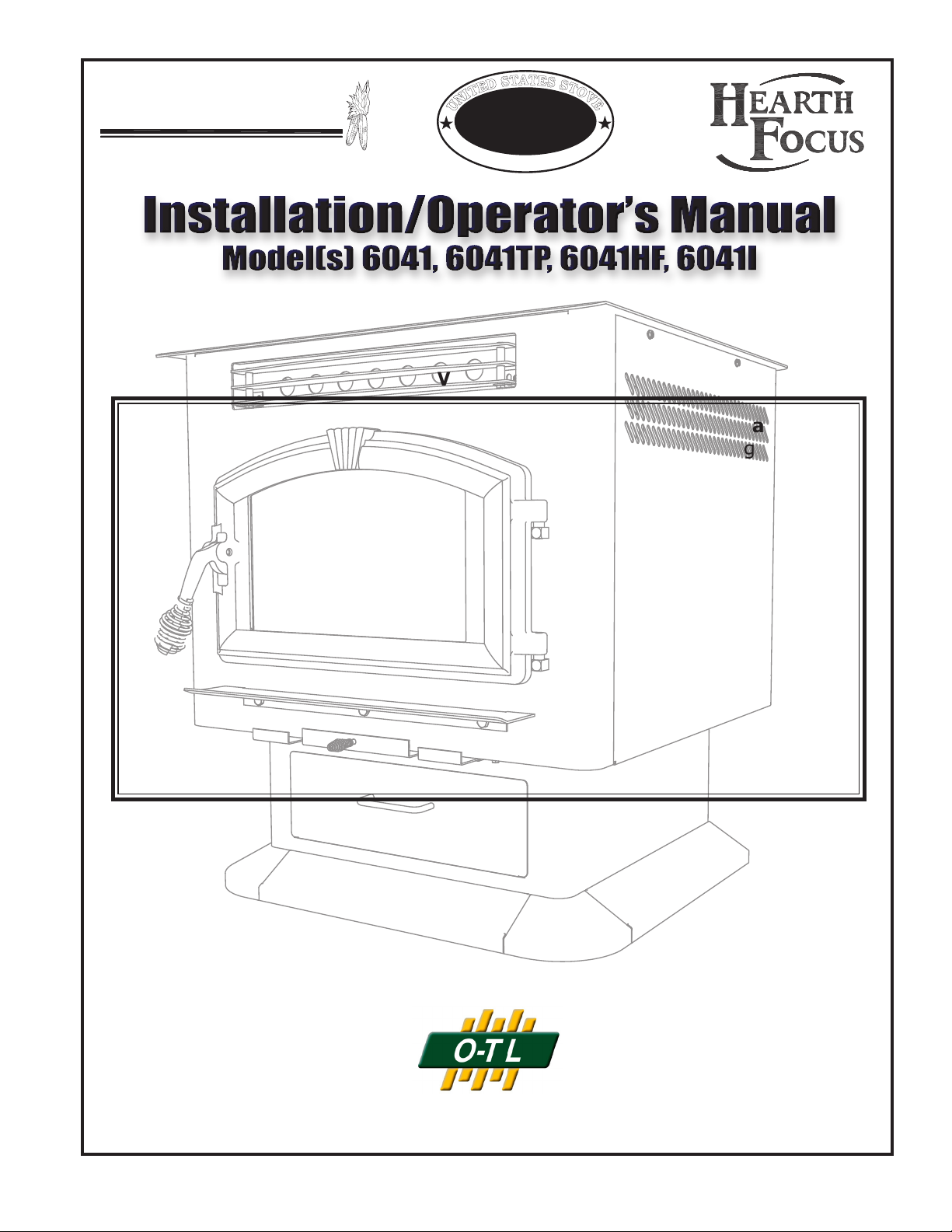
USSC 1
851772 rev A
C
S
S
U
C
O
M
P
A
N
Y
U
N
I
T
E
D
S
T
A
T
E
S
S
T
O
V
E
United States Stove Company • 227 Industrial Park Road, P.O. Box 151 • South Pittsburg, TN 37380 • www.usstove.com
Safety Tested to ASTM-E 1509, (UM) 84-HUD
American Harvest
Safety Notice: If this heater is not properly installed, a house re may result.
For your safety, follow the installation directions. Contact local building or re of-
cials about restrictions and installation requirements peculiar to your area. Do
Not Plug this appliance into an electrical outlet before reading and understanding
all operations and always unplug the unit before attempting any work or main-
tenance. Do not connect this heater to any chimney ue already serving another
appliance. Carefully observe and maintain all clearances to combustibles.
A note about fuel: Use only dried shelled corn with a moisture content of 14%
or less (11 to 12% provides the best results); any pellet fuel used should
have an ash content of 1% or less. If not, efciency will suffer. This heater has
successfully burned pellets with a 2-1/2% ash content, though less ash is preferred
and more efcient.
Your American Harvest Multi-Fuel Heater operates on a negative pressure. There-
fore, all venting connections (elbows, T-pipe) must be sealed and airtight.
i
Use Hi-Temp silicone at each joint or connection.
READ THIS ENTIRE MANUAL, THOROUGHLY, BEFORE ATTEMPTING TO INSTALL AND/
OR BURN YOUR NEW AMERICAN HARVEST *MULTI-FUEL HEATER. FAILURE TO FOLLOW
THESE INSTRUCTIONS MAY RESULT IN PROPERTY DAMAGE, BODILY INJURIES OR
EVEN DEATH.
*This heater is capable of burning wood, biomass pellets and a wide variety of grains,
including corn, soybeans, cherry and olive pits, and all larger seeds.
SAVE THESE INSTRUCTIONS
UNITED STATES STOVE COMPANY GRANTS NO WARRANTY, IMPLIED OR STATED,
FOR THE INSTALLATION OR MAINTENANCE OF THE HEATER AND ASSUMES NO
RESPONSIBILITY FOR ANY CONSEQUENTIAL DAMAGE(S).
Tested &
Listed By
Portland
Oregon USA
Omni-Test Laboratories, Inc.
US
2 USSC
NOTE: YOUR UNIT MUST BE INSTALLED BY A
QUALIFIED INSTALLER, such as an NFI (National
Fireplace Institute) Certied Specialist
You’ve purchased one of America’s Finest Multi-fuel Burning Heaters. By heating
with fuels such as corn and pellets, you’re helping CONSERVE AMERICA’S ENERGY!
We strongly suggest installing smoke detectors in your home if not already installed.
Initial burn off may cause slight smoke and odor the rst few hours of operation.
Perform initial burn outside if possible
SPECIFICATIONS
United States Stove Company reserves the right to alter products, specications and price without
notice.
Safety Tested & Listed to ASTM- E 1509, (UM) 84-HUD, by OMNI Test Laboratories, Inc., Portland,
Oregon USA
BTU output will vary, depending on the brand, type and quality of fuel and the moisture content. Consult your
dealer for best results.
Based on post 1982 home construction, requiring 35 BTU/Hr per Sq. Ft.
Remember, this heater should not be used as the only source of heat in the house.
Power outages and neglect of periodic maintenance will result in a total loss of heat.
Heat Input (as tested) 45,000 BTU/HR
Heat Output
(as tested) 35,100 BTU/HR
Heating Capacity 1,000-2,000 Sq. Ft
Fuel Storage Capacity 60 Lbs.
Width 29 in./737mm
Height 6041TP/6041HF
31 in./787mm
6041I
24 in./610mm
Depth 28 in./711mm
USSC 3
1
2
Assembly
1. Unpack unit and make sure all components are included; (4) Legs,
and all hardware for installation.
2. Fold the corner padding from the carton and lay it on the oor behind
the unit. This is used to hold the heater up off the oor to install the
legs. Gently tilt the heater on its back, door opening up.
3. Assemble the legs as shown using the eight(8) 1/4-20 bolts supplied.
4. After all bolts and screws have been tightened properly, carefully
set the heater back up on the legs.
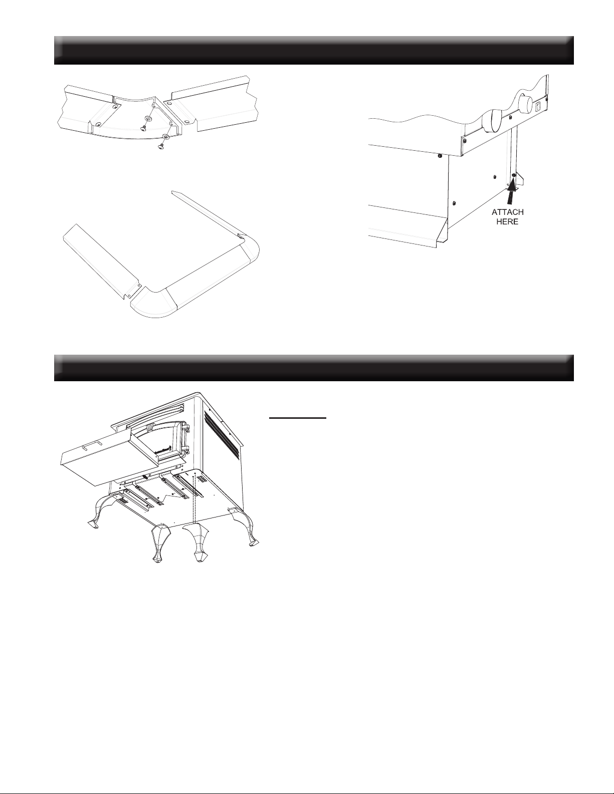
6041HF ASSEMBLY
6041TP PEDESTAL TRIM ASSEMBLY
Assemble trim pieces as shown with the screws
provided in the parts bag.
After trim assembly, attach to the pedestal base at the
location shown using the screws provided.
4 USSC
(a)
(a)
(c)
(h)
(f)
(g)
(b)
(e)
6041I ASSEMBLY
(i)
(j)
For the following assemblies, we suggest locating the unit
near it’s desired location. Depending on installation, you
may want to connect the exhaust venting before installing
the facade parts.
Assembly - Facade (Surround)
Remove contents from packaging and make sure you have
all components:
(2) Top Facade (a)
(1) Left Side Facade (b)
(1) Right Side Facade (c)
(4 pieces)Facade Trim Kit (d)
(1) Feed Door Spring Handle (e)
(1) Damper Spring Handle (f)
(1) Ash Pan “U” shaped Handle (g)
(1) Access Door Knob (h)
(1) PCB Cover (i)
(1) Panel Cover (j)
(1) Auger (in ash pan)
(1) Power Cord
(1) Burnpot Poker (k)
Mounting Hardware
Start by mounting either the left or right side facade pieces to
the unit using four(4) of the supplied #10 x 1/2 screws. Then
put the two(2) top facade pieces together with two(2) of the
#10 x 1/2 screws provided. Attach the top facade assembly
to the unit with eight(8) of the same screws.
Control Board (PCB) Re-location
Remove the left side front panel from the unit. While holding
the PCB with one hand, remove the two(2) hex head screws
holding the board in place. It is not necessary to unplug the
PCB cable. Route the board and cable through the opening
and mount it to the Left Facade using two of the #10 x 1/2
phillips head screws provided. Then attach the PCB cover
to the back of the facade covering the board. Next, use the
two hex head screws removed earlier and mount the cover
panel over the opening where the PCB was located. See il-
lustration to the left.
Facade Trim
Remove trim from shipping tube. There should be one(1)
left side, one(1) right side, two(2) top pieces, and mounting
hardware. Using one blank corner key and one corner key
with set screws, assemble the left trim and one of the top
pieces together. As illustrated, place the blank key behind
the key with the set screws. Adjust corners and tighten set
screws. Repeat this for the right side
Before removing tape, place trim assembly against facade
to get an idea of how it is to be mounted. Remove the strip
from the adhesive and carefully secure the trim in place by
rmly pressing it to the facade.
Burnpot Poker
The burnpot poker may be used several ways. It is used
primarily as a fuel-loading assistant to help push the fuel to
the rear of the hopper for maximum fueling. It may also be
used for cleaning of ashes or removal of clinkers.
DISCONNECT THE POWER CORD BEFORE SERVICING THIS Heater
2
3
4
B B
REV DESCRIPTION DATE BY
(k)
(d)
USSC 5
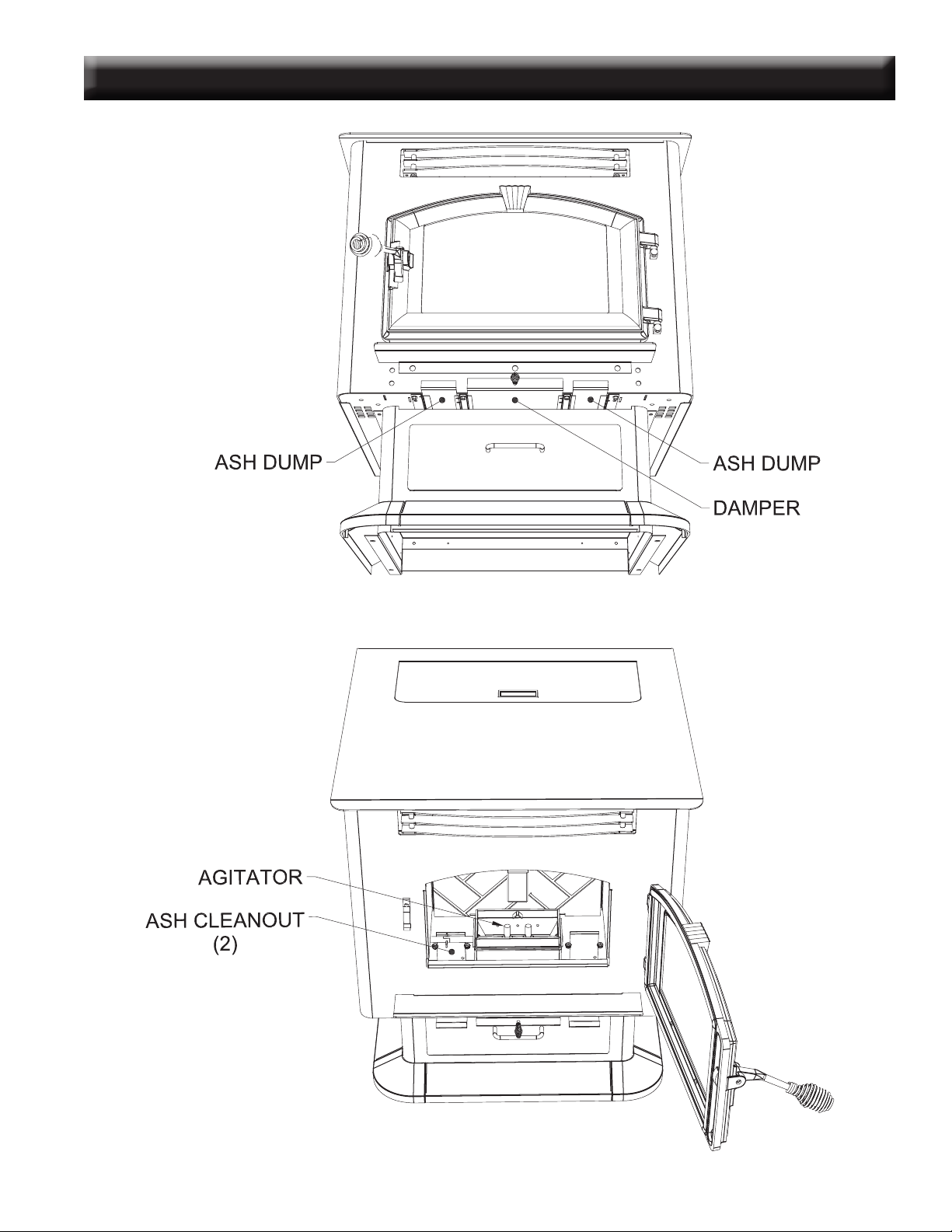
COMPONENT LOCATION

6 USSC
Ashes will have to be removed from the heater for proper operation. See cleaning procedure.
Your Multi-fuel heater, due to the nature of solid fuels, will require brief periodic attention. Please do not expect to light
your heater and walk away from it. A few moments of adjustment and cleaning is an important part of burning solid
fuels, due to the vast differences in fuel, humidity and outside temperature.
The Multi-fuel heater has been designed to burn dry shelled corn, wood pellets and other pelletized fuels that meet As-
sociation of Pellet Fuel Industries standards.
SAFETY STEPS
IMPORTANT: Proper installation of this heater is necessary for safe and efcient operation. In-
stalling this product improperly may result in a house re and personal injury. All applicable building
codes for your location must be followed. In areas where building codes require additional steps to
the installation of this product not included in this manual, the building codes will take precedent
and must be followed. Contact your local building inspector to obtain any necessary permits or
inspection guidelines before installing the product.
• The American Harvest heater is designed to burn dry shelled corn, cherry pits, or pelletized fuel such as
wood and biomass pellets. The burning of other solid fuels such as cord wood or wood chips in this heater
is not permitted.
• This product requires simple periodic maintenance for proper operation and long life of the heater. Read
and follow the maintenance schedule closely.
• DISCONNECT THE POWER CORD BEFORE SERVICING THIS HEATER!
• A power surge protector is required. The unit must be plugged into a grounded 110-volt power
source. Circuit Boards are very expensive - protect yours!
• Always route the power cord away from the unit. Do not route cord in foot trafc areas. Do not pinch cord
under furniture. Do not route the cord across the exhaust pipe.
• A working smoke detector must be installed in the same room as this product.
• Flammable or explosive liquids such as gasoline, naphtha, alcohol, lighter uid, or engine oil must NEVER
be used in or around this heater. These liquids must be stored well away from this heater as the open
ame in the burner chamber could ignite the fumes of such liquids. Do not burn garbage in this unit.
• The moving parts of this heater are propelled by high torque electric motors. The Auger and Fuel Agitator
can cause severe injury to body parts that may get near them. Keep all body parts away from the Auger
and Fuel Agitator while the heater is plugged into an electrical outlet. These moving parts may begin to
move at any time while the heater is plugged in.
• According to HUD requirements, when installed in a mobile home, this heater must be grounded directly
to the steel chassis of the mobile home and bolted to the oor. Direct air access must be provided - Use
69FAK Fresh Air Kit
• This heater is not intended for use in commercial installations.
• Do not connect this heater to “B” vent. Use UL Listed Pell Vent ONLY!
• Do not elevate the re by use of grate or any other means other than the supplied burnpot.
BURNING SOLID FUELS

USSC 7
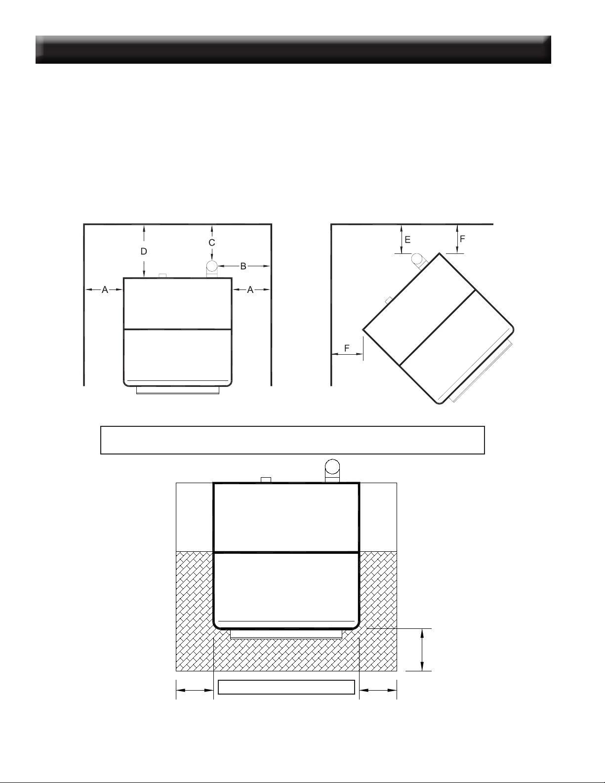
FLOOR PROTECTION
The Multifuel Heater may be installed on a combustible oor, with proper oor protection, or on a masonry hearth.
The hearth or noncombustible oor protector must extend a minimum of (6) inches (152mm)in front and (6) inches
(152mm) from each side of the unit.
INSTALLATION REQUIREMENTS
SHELLED CORN (Dry, preferably corn with 11- 12% moisture content)
• Corn must contain less than 14% moisture content. Wet corn will rapidly deteriorate heater components,
reduce efciency and void all warranties. Purchase a moisture tester if in doubt.
• Corn must be clean and free from debris. Never burn corn right from the eld. Damage caused by dirty corn is not
covered by the product warranty. Ask for clean ltered bagged corn only. Stalk parts, excessive nes and cob rem-
nants will clog the auger. Check your corn for foreign objects.
• NEVER BURN SEED CORN IN YOUR Heater. Seed corn is treated with chemical pesticides that are harmful or
fatal if swallowed, therefore, seed corn is dangerous to have in the house, especially where children can reach it.
• Never burn “Deer Corn.” It frequently contains molasses, sugars and salts.
• Store your corn supply in a dry place and keep bags or container sealed to prevent your corn from absorbing excess
moisture. Test the moisture content periodically to ensure the proper dryness.
• There are many varieties of corn grown around the world. Each variety has unique characteristics including the shape
and size of the kernel. Your heater will burn more consistently with a small to midsize kernel corn. If the kernel size
of the corn varies greatly or if you switch sources frequently, you will get a less consistent burn. Therefore, purchas-
ing corn from the same source will help achieve a more consistent burn. DO NOT USE CORN WITH A HIGH WAX
CONTENT!
WOOD and BIOMASS PELLETS
• As with corn, be consistent in your pellet supplier. Pellets will vary in content and burn characteristics from supplier
to supplier. A consistent supply of pellets will result in a more consistent and efcient burn.
• Check your pellets for foreign objects. Your heater warranty will not cover damage done to your heater due to foreign
objects in the fuel supply.
• Store your pellets in a dry place to prevent them from absorbing added moisture.
• To decrease sawdust buildup, the hopper and auger tube will need to be vacuumed out after every 6-8 bags of pellets
or more often if the pellets are poor quality. The hopper should be empty of fuel when this is performed. You may
have to screen each bag of pellets if sawdust becomes a problem.
• Wood Pellets vary in size and ash content from less than 1% to 3% or more. Your heater will burn more efciently
with small to midsize pellets (Preferred pellet size is 1/4” diameter x 1” length). Low ash content pellets will allow
you to burn the heater longer between cleanings. Only wood pellets manufactured to the Pellet Fuel Institute (P.F.I)
standard for residential pellets fuels are recommended. Performance will suffer if nonstandard pellets are used. Consult
your local American Harvest dealer for more information on approved wood pellet fuel.
CAUTION:
DO NOT PLACE SUCH FUELS WITHIN THE SPACE HEATER’S
INSTALLATION CLEARANCES OR WITHIN THE SPACE REQUIRED FOR FUELING AND
ASH REMOVAL.
BURNING SOLID FUELS continued...
8 USSC
CLEARANCES TO COMBUSTIBLES 6041(TP)(HF)
The heater must be installed with the following minimum clearances to side and back wall combustible materials.
NOTE: These are minimum clearances to combustible walls established by the testing lab.
PARALLEL - A - Sidewall to Top Edge of Unit 8 in./203mm
B - Sidewall to Flue 13 in./330mm
C - Backwall to Flue 3 in./75mm
D - Backwall to Unit 9 in./228mm
CORNER - E - Adjacent Wall to Flue 3 in./75mm
F - Adjacent Wall to Unit 4 in./100mm
BACK WALL
SIDE WALL
SIDE WALL
Backwall / Sidewall
Parallel
BACK WALL
Corner Installation
NOTE:
Allow sufcient space to remove the left and right side panels for maintenance purposes.
6”
min.
HEARTH PROTECTION
These clearances must be maintained.
6”
min.
6”
min.
USSC 9
CLEARANCES TO COMBUSTIBLES 6041I
10 USSC
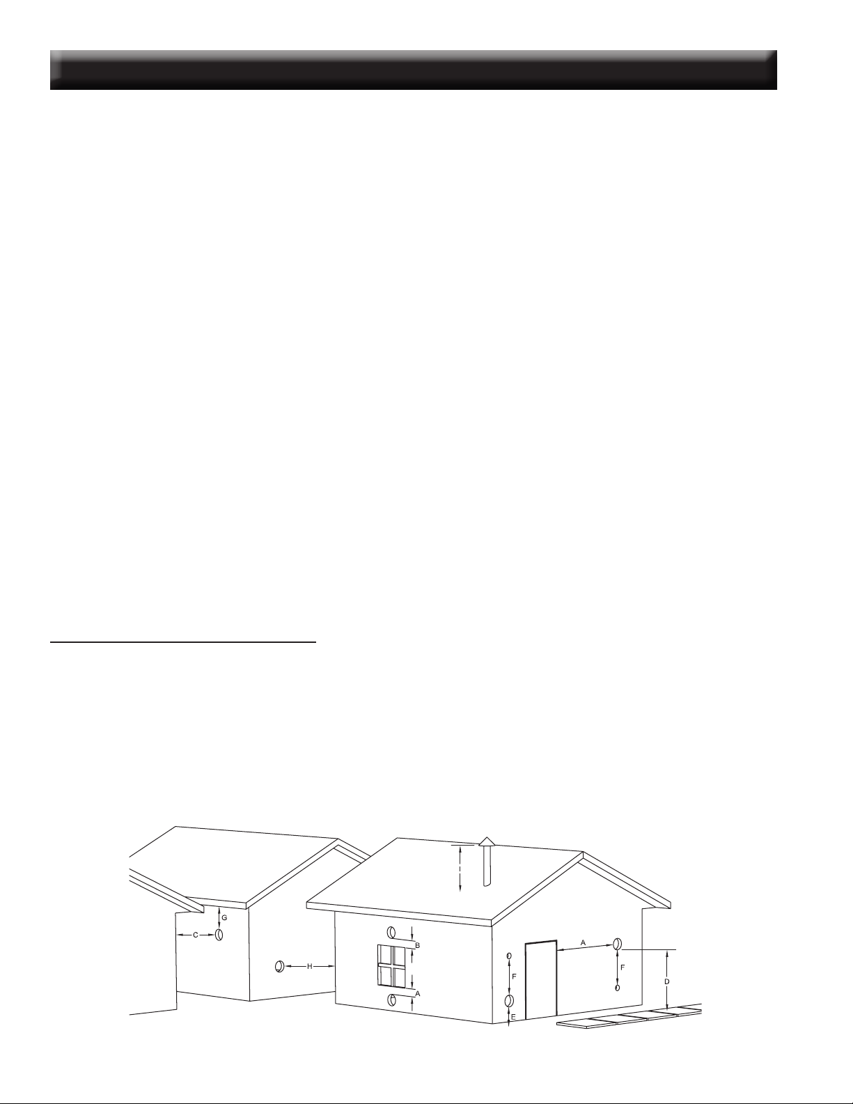
GUIDELINES FOR EXHAUST VENTING SYSTEMS DESIGN
It is recommended that only an authorized installer install your multi-fuel heater, preferably an NFI certied specialist.
The following installation guidelines must be followed to ensure conformity with both the safety listing of this heater and to local
building codes.
INSTALL VENT AT CLEARANCES SPECIFIED BY THE VENT MANUFACTURER.
• A UL listed 3” or 4” type “PL” pellet vent exhaust system must be used for installation and attached to the pipe connector provided
on the back of the heater. Use a 3” to 4” adapter for 4” pipe. A cap must be used at the termination of type “L” vent chimneys.
4” PL is required for elevations above 2,500 feet above sea level.
• Do not terminate vent in any enclosed or semi-enclosed area, such as; carports, garage, attic, crawl space, under a sundeck or porch,
narrow walkway or close area, or any location that can build up a concentration of fumes such as a stairwell, covered breezeway
etc.
• Vent surfaces can get hot enough to cause burns if touched by children. Noncombustible shielding or guards may be required.
• Do not install a ue damper in the exhaust vent of this unit.
• Termination must exhaust above air inlet elevation. Installation MUST include three (3) vertical feet of pellet vent pipe. This will
create some natural draft to prevent the possibility of smoke or odor during appliance shutdown and to keep exhaust from caus-
ing a nuisance or hazard from exposing people or shrubs to high temperatures. Do not connect this unit to a chimney ue
serving another appliance. Do not connect directly to a masonry chimney.
• The installation must include a cleanout tee to enable collection of y ash and to permit periodic cleaning of the exhaust system.
90
°
elbows accumulate y ash and soot thereby reducing exhaust ow and performance of the heater. Each elbow or tee reduces
draft potential by 30% to 50%. Use no more than 180 degrees of elbows (two 90-degree elbows, or two 45-degree and one
90-degree elbow, etc.) and one cleanout tee to maintain adequate draft. Cleanout tees and elbows should not be connected to
the rear of the unit unless a 3-inch adapter is used.
• Total length of horizontal vent must not exceed 48”(4ft.)/1,200mm. The maximum recommended vertical venting height is 12-feet
for 3-inch type “PL” vent. For venting higher than 12-feet, 4-inch “PL” vent must be used. All joints in the vent system must be
fastened by at least 3 screws, and all joints must be sealed with RTV silicone sealer to be airtight.
• The area where the vent pipe penetrates to the exterior of the home must be sealed with silicone or other means to maintain the
vapor barrier between the exterior and the interior of the home.
NOTE: These are guidelines only. Proper venting is accomplished by design and necessary requirements. In
most installations 3 inch diameter venting is adequate. If it does not vent properly you will have to change it to 4
inches. You should not exceed 4 inch diameter venting.
DO NOT CONNECT TO ANY AIR DISTRIBUTION DUCT OR SYSTEM
VENT TERMINATION CLEARANCES:
A) Min. 4-ft clearance below or beside any door or window that opens.
B) Min. 1-ft clearance above any door or window that opens.
C) Min. 3-ft clearance from any adjacent building.
D) Min. 7-ft clearance from any grade when adjacent to public walkways.
E) Min. 2-ft clearance above any grass, plants, or other combustible materials.
F) Min. 3-ft clearance from a forced air intake of any appliance.
G) Min. 2-ft clearance below eaves or overhang.
H) Min. 1-ft clearance horizontally from combustible wall.
I) Must be a minimum of 36-inches above the roof and 24-inches above the highest point or the roof within 10-feet.
 Loading...