


CS100UT1CS1
Finest Quality
From the library of: Superior Sewing Machine & Supply LLC
ADJUSTING INSTRUCTION I PARTS
MANUAL
CS1
00 SERIES, DIFFERENTIAL FEED,
HIGH SPEED CYLINDER
MANUAL
NO. PT9641
BED
FOR DEVICES
UT1CS1
UT2CS1
UT3CS1
UT4CS1
UT5CS1
Rev.2-23-98
MACHINES

for
From the library of: Superior Sewing Machine & Supply LLC
Devices
Adjusting Instructions/Parts
UTlCSl
..
UT2CS1, UT3CS1,
Manual
UT4CSL
PT9641
UT5CS1
Second
Rights Reserved In All
This
parts
manual
machines. It
style) & Operator•s
It
is
the
desire
designed specifically for your
This
manual
may
incorporate
has
can
be
Manual
of
Union Special
has
been
a slight
been
prepared
used
in
conjunction
OP9637.
comprised
modification
Edition
to
that
each
machine
on
the
Copyright
1997
Countries
by
Union
Printed
Special
in
U.S.A
PREFACE
assist
you in
locating
with Union Special Parts Manuals
machine
and
are
basis
of
configuration in illustrations
run
manufactured
of
available
NEW
at
its
optimum
information.
individual parts
with utmost precision
Corporation
February
PT9512
performance.
Changes
or
part
1998
or
or
PT9425
in design
numbers.
assemblies
Parts listed in this
to
assure long lasting seNice.
on
the
(depending
and/or
improvements
CS l 00
on
manual
Series
machine
are
2

CONTENTS
From the library of: Superior Sewing Machine & Supply LLC
•SAFETY
•
TENSION
•THREAD
•THREADING
•UNDERBED
•UNDERBED
•UNDERBED
•UNDERBED
•UPPER
•TENSION
•UNDERBED
•LOWER
•STOP
•GUIDE
•UNDERBED
•ELECTROPNEUMATIC
•SEITING
•ADJUSTING
. •SOLENOID/PNEUMATIC
•PNEUMATIC/ELECTRIC
•SETIING
•NEEDLE
•AIR
•THREAD
•UNDERBED
•ELECTRIC
•ELECTRIC
•
ELECTRIC
•ELECTRIC
•PNEUMATIC
•PNEUMATIC
•PNEUMATIC
•PRESSER
•NEEDLE
•PNEUMATIC
•NUMERICAL
•NUMERICAL
RULES
RELEASE
PULL-OFF
THREAD
KNIFE
SPRING
KNIFE
DISTANCE
DISTANCE
PROXIMITY
THREAD
THREAD
FLOW
..............................................................................................................................................................
TENSION
PRESSER
THREAD
DRIVE
SPREADER
FOOT
THREAD
......................................................................................................................................................... 4
(UNDERBED
.................................................................................................................................................. 6
DIAGRAM .......................................................................................................................................... 7
TRIMMER
THREAD
THREAD
THREAD
AND CLAMPING
THREAD
THREAD
THREAD
THREAD
CONTROL
DRIVE
THREAD
COVER
INDEX
INDEX
TRIMMER
TRIMMER
TRIMMER
..................................................................................................................................................
TRIMMER
FRONT
TO
....................................................................................................................................................
.................................................................................................................................................
TRIMMER
DRIVE
SWITCH
WIPER
CATCH
BLOWER
.................................................................................................................................................
TRIMMER
FOOT
WIPER
DOUBLE
THREAD
DOUBLE
WIPER
LIFTER
...........................................................................................................................................
BLOWER
THREAD
OF
OF
THREAD
(ELECTRIC)
ASSEMBLY
ASSEMBLY
ASSEMBLY
SPRING
ASSEMBLY
BACK
...........................................................................................................................
.............................................................................................................................
...............................................................................................................................
................................................................................................................................
.................................................................................................................................
THREAD
COVER
........................................................................................................................................
PARTS
PARTS
THREAD
KNIFE
STROKE
ASSEMBLY
ASSEMBLY
LIFTER
ASSEMBLY
ASSEMBLY
ACTION
TRIMMER
ACTION
ASSEMBLY
ASSEMBLY
TRIMMER
.............................................................................................................................
.............................................................................................................................
TRIMMER)
........................................................................................................... 8
............................................................................................................ 9
..........................................................................................................
..........................................................................................................
..............................................................................................................
..........................................................................................................
WIPER
............................................................................................................
TRIMMER
............................................................................................................
.................................................................................................................
..........................................................................................................
.......................................................................................................
..................................................................................................................
ASSEMBLY
ASSEMBLY
ASSEMBLY
.............................................................................................................
.................................................................................................................
ASSEMBLY
............................................................................................. 5
...........................................................................................
...................................................................................................
..........................................................................................
..............................................................................................
..........................................................................................
10
11
11
11
12
12
12
12
13
13
14
15
16
17
18
19
19
21
23
25
27
29
31
33
35
37
39
41
43
50
51
3
1 .
From the library of: Superior Sewing Machine & Supply LLC
Before
starting
operators.
putting
of
each
the
machines
machine
described
is
only
in this
permitted
SAFETY
manual
after
RULES
into
taking
service,
notice
carefully
of
the
read
instructions
the
instructions. The
and
by
qualified
IMPORTANT!
2.
Observe
3. The
4.
5.
6.
7.
sewing
until
conformed
Each
described
the
description,
All
safety
of
the
Wear
In
case
and
The
warning
the
it
has
been
machine
in
devices
machine
safety
of
machine
changes
Before
the
motor
national
machines
ascertained
with
the
is
only
paragraph
is
not
must
without
glasses.
are
made
hints in
putting
safety
EC
allowed
conversions
the
the
supplier.
rules
described
that
Council
"STYLES
as
foreseen.
be
in
position
the
appertaining
at
your
instructions
to
machine
valid
in
this
the
Directives
be
OF MACHINES"
and
own
into
for
instruction
sewing
used
when
changes
risk.
are
marked
your
units
(89/392/EEC,
as
foreseen.
the
safety
service,
country.
manual
which
of
this
machine
devices
all
valid
with
also
read
are
these
sewing
Annex
The
foreseen
instruction
is
ready
is
prohibited.
safety
one
of
these
the
safety
prohibited
machines
II
B).
use
manual.
for
work
rules
must
two
rules
from
of
the
Another
or
in
be
considered.
symbols:
and
instructions
being
operation.
put
will
be
built
particular
use,
going
from
into
service
into,
have
machine
beyond
Operation
Conversions
is
8.
When
the
main
8.1
8.2
8.3
8.4
8.5
9.
Maintenance,
special
10.
Any
supervision
11. Work
described
12.
Before
disconnected
necting
removed
doing
switch
When
When
dog,
When
When
When
skilled
work
on
doing
from
the
threading
replacing
needle
leaving
doing
using
repair
personnel
on
the
of
special
parts
and
in
the
maintenance
from
compressed
by
bleeding.
following
or
by
pulling
needle(s),
any
guard,
the
workplace
maintenance
clutch
applicable
motors
and
electrical
skilled
equipment
the
compressed
the
machine
out
the
parts
such
folder.
conversion
under
air
fabric
work.
without
consideration
equipment
personnel.
under
sections
and
repair
supply
main
looper,
as
and
work
electrical
of
air
(i.e.
has
to
be
plug:
spreader
needle(s),
guide
when
actuation
work
etc.
the
(see
of
must
standard
on
supply.
pneumatic
disconnected
etc.
presser
workplace
lock,
wait
item
8)
must
the
instructions.
be
done
power
the
In
is
sheet
pneumatic
case
equipment
from
foot
throat
is
unattended.
until
the
be
done
by
an
electrician
not
permitted.
DIN VDE 0105.
equipment
of
existing
with
residual
air
the
plate,
motor
only
tank),
power
supply
looper,
is
stopped
by
trained
or
under
Permissible
the
machine
air
pressure
the
pressure has
by
turning
spreader,
totally.
technicians
direction
exceptions
has
after
discon-
feed
and
are
to
to
off
or
be
be
4
TENSION
From the library of: Superior Sewing Machine & Supply LLC
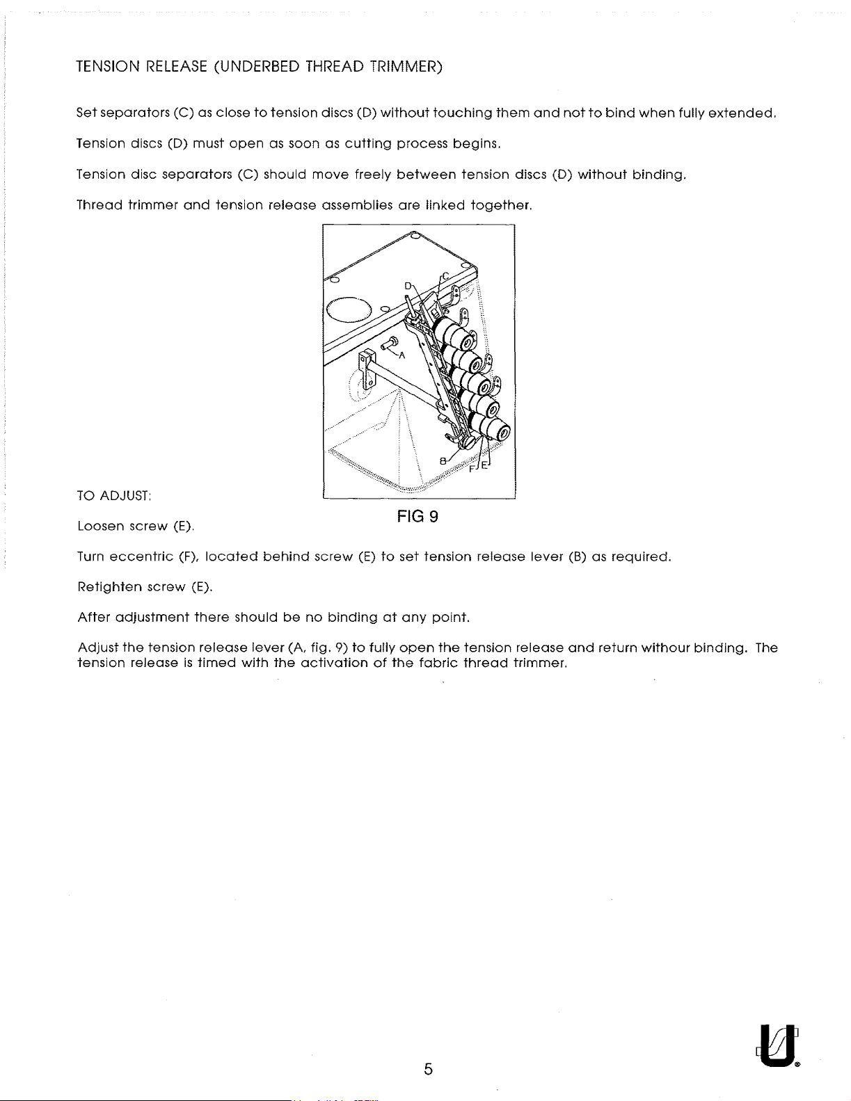
Set
separators
RELEASE
(C)
as
(UNDERBED
close
to
tension
THREAD
discs
(D)
TRIMMER)
without
touching
them
and
not
to
bind
when
fully
extended.
Tension discs
Tension
Thread
TO
Loosen
disc
trimmer
ADJUST:
screw
(D)
must
separators
and
tension
(E).
open
(C)
as soon as
should
release
move
assemblies
cutting
freely
process
between
are
linked
FIG9
begins.
tension
together.
discs
(D)
without
binding.
Turn
eccentric
Retighten
After
adjustment
Adjust
tension
the
screw
tension
release
(F),
(E).
there
release
is
timed
located
should
with
behind
lever
the
screw
be
no
(A,
fig.
activation
(E)
binding
9)
to
to
at
fully
of
set
any
open
the
tension
point.
the
fabric
release
tension
thread
lever
release
trimmer.
(B) as
and
return
required.
withour
binding.
The
5
THREAD
From the library of: Superior Sewing Machine & Supply LLC
PULL-OFF
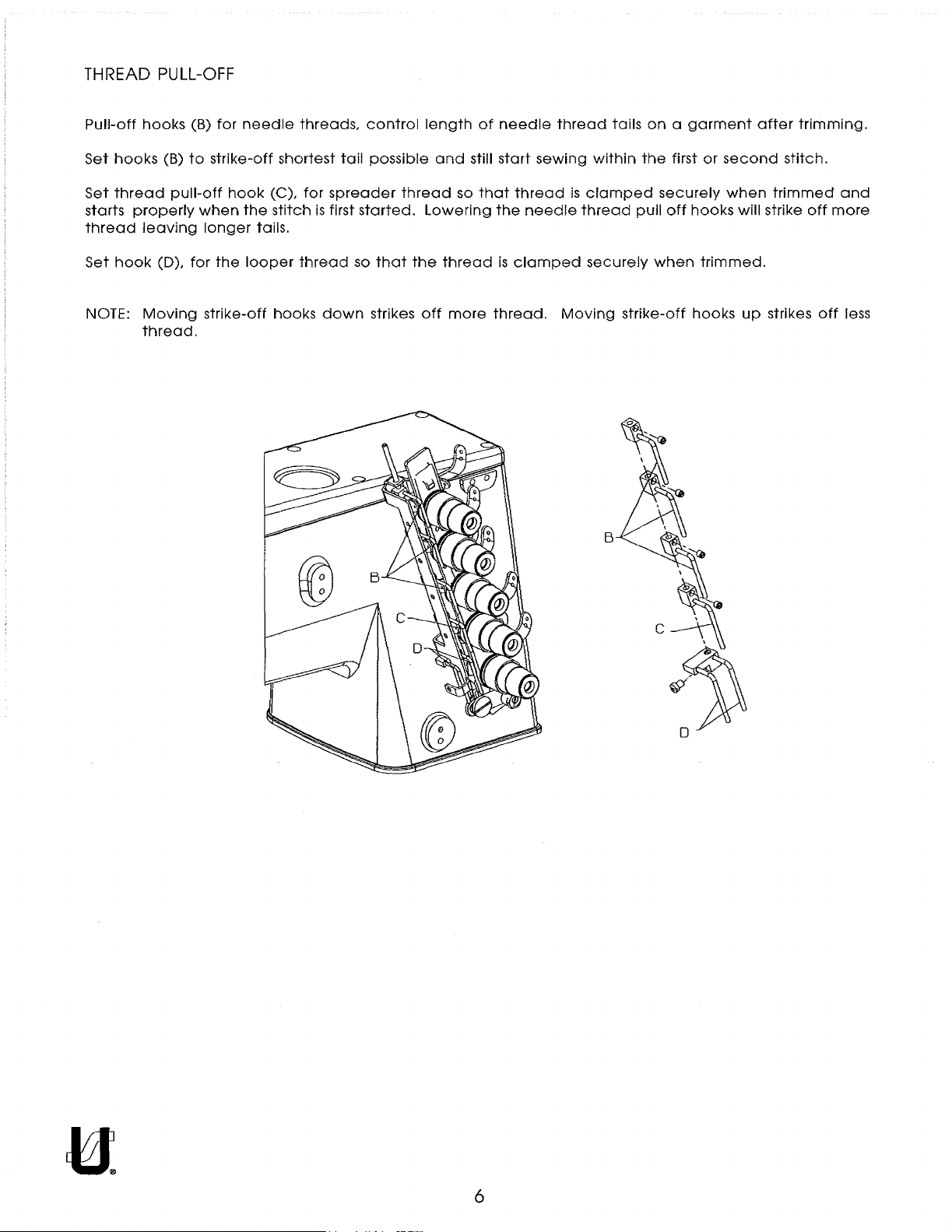
Pull-off
Set
hooks
Set
thread
starts
thread
Set
hook
NOTE:
hooks
(B)
pull-off
properly
leaving
(D),
Moving
thread.
(B)
for
to
strike-off
hook
when
longer
for
the
strike-off
needle
shortest
(C),
the
stitch
tails.
looper
hooks
threads,
tail
for
spreader
is
first
thread
down
control
possible
started.
so
that
strikes
length
and
thread
lowering
the
off
of
still
so
that
thread
more
needle
start
thread
the
needle
is
clamped
thread.
thread
sewing
is
Moving
tails
within
clamped
thread
securely
strike-off
B
on a garment
the
first
or
securely
pull
off
hooks
when
trimmed.
hooks
after
second
when
will strike
up
trimming.
stitch.
trimmed
off
strikes
off
and
more
less
6
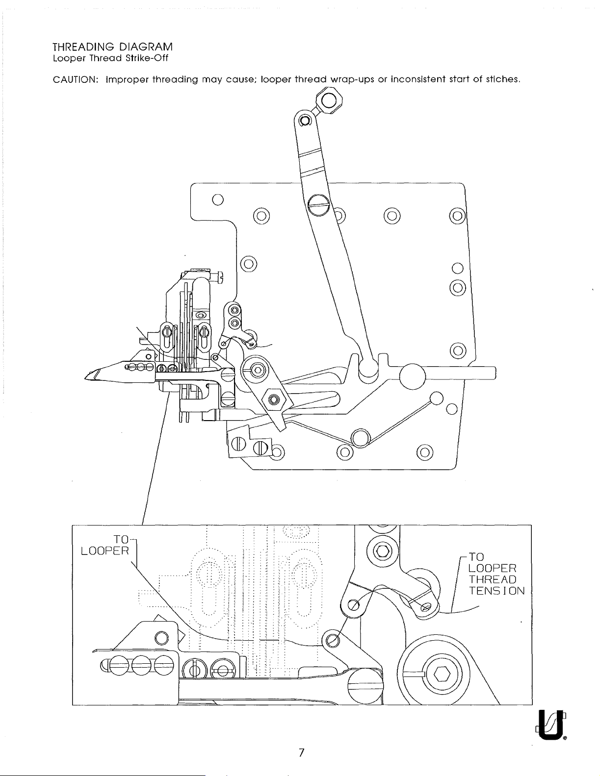
THREADING
From the library of: Superior Sewing Machine & Supply LLC
Looper
Thread
DIAGRAM
Strike-Off
CAUTION:
Improper
threading
may
0
cause;
@
looper
@
thread
wrap-ups
or
inconsistent
@
start
@
0
@
of
stiches.
TO
LOOPER
:"
/::·--:::. - .
..
~
. . .:-~ .
@
-·
TO
LOOPER
THREAD
TENSION
7
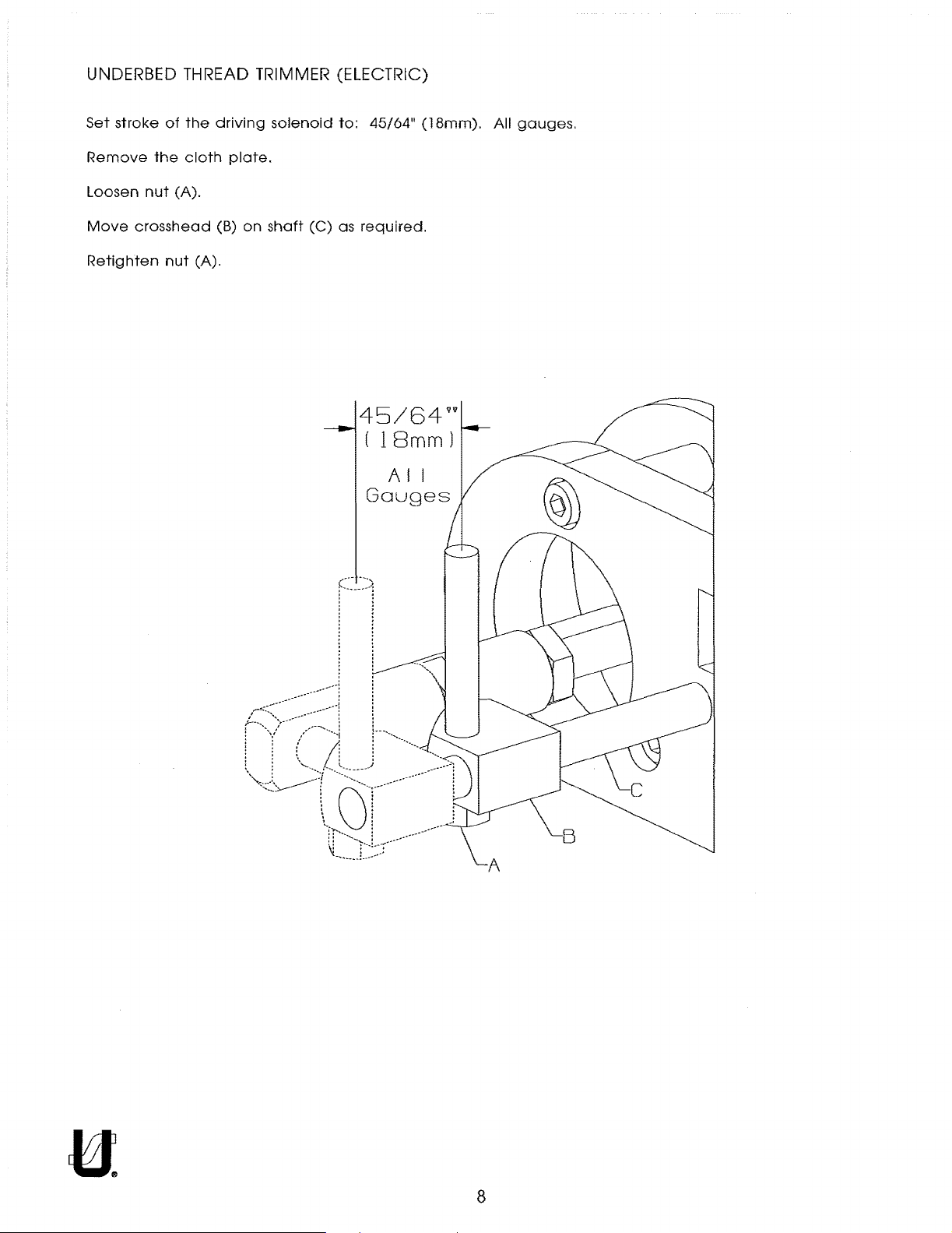
UNDERBED THREAD TRIMMER (ELECTRIC)
From the library of: Superior Sewing Machine & Supply LLC
Set
stroke
Remove
Loosen
Move
Retighten
crosshead
the
nut
of
(A).
nut
the
cloth
(A).
driving
plate.
(B)
on
solenoid
shaft
(C)
to:
45/64
as
required.
45/64vv
(
18mm)
AI
Gouges
11
(18mm).
I
All
gauges.
8
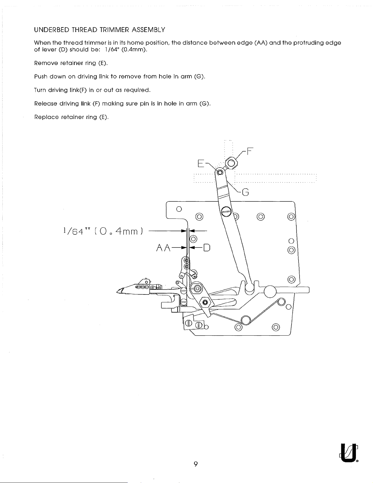
UNDERBED
From the library of: Superior Sewing Machine & Supply LLC
THREAD
TRIMMER
ASSEMBLY
When
of
Remove
Push
Turn
Release
Replace
the
lever
down
driving
thread
(D)
should
retainer
on
link(F) in
driving
retainer
trimmer
be:
ring (E).
driving
link (F)
ring (E).
1/64
link
or
out
making
is
to
in its
as
home
11
(0.4mm).
remove
required.
sure
position,
from
pin
is
hole
in
hole
the
in
in
0
distance
arm
(G).
arm
E
@
between
(G).
edge
(AA)
and
the
protruding
edge
l/64v'l
(0o4mm)
0
@
@
9
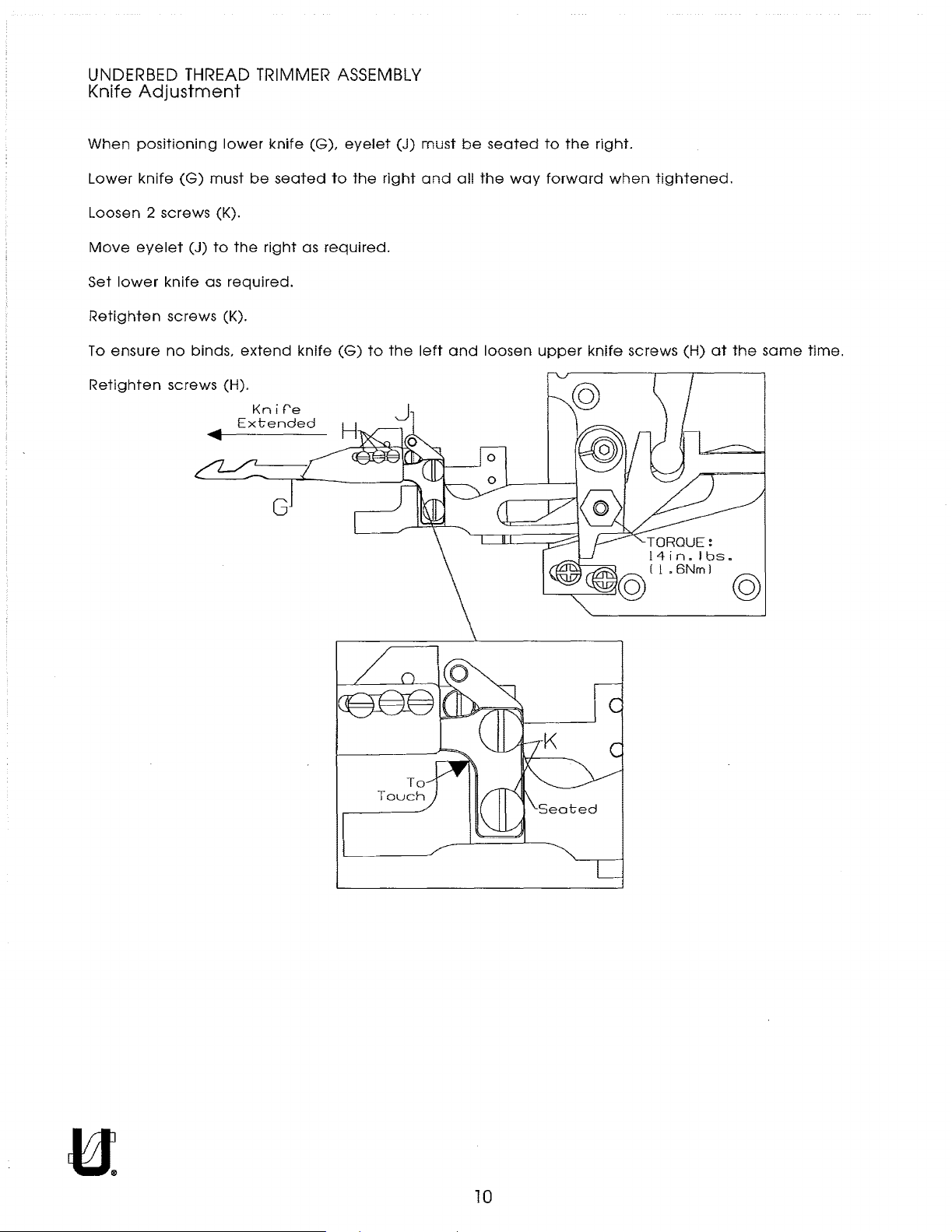
UNDERBED
From the library of: Superior Sewing Machine & Supply LLC
Knife
Adjustment
THREAD
TRIMMER
ASSEMBLY
When
Lower
Loosen 2 screws (K).
Move
Set
Retighten
To
Retighten
positioning
knife
eyelet
lower
ensure
lower
(G)
must
(J)
to
knife
as
required.
screws (K).
no
binds,
screws (H).
knife
be
seated
the
right
extend
Knif'e
Extended
(G),
as
required.
knife
eyelet
to
the
(G)
to
(J)
right
the
must
and
left
be
all
and
seated
the
way
loosen
to
the
right.
forward
upper
when
knife
tightened.
screws
(H)
at
TORQUE:
14
in. I bs
._______,.,.--------.:=..1@
I l • 6Nm I @
the
•
same
time.
10
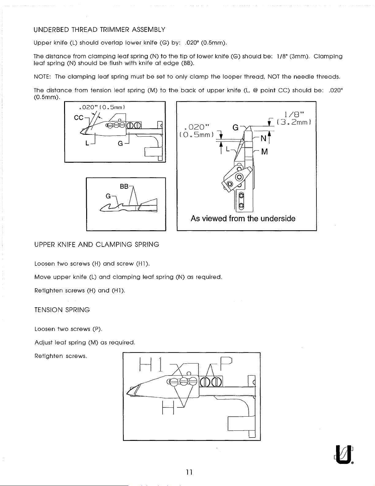
UNDERBED THREAD TRIMMER ASSEMBLY
From the library of: Superior Sewing Machine & Supply LLC
Upper
The
leaf
knife
distance
spring (N)
(L)
from
should
clamping
should
overlap
be
flush
leaf
with
lower
spring
knife
knife
(N)
at
(G)
to
by:
the
edge
.020
tip
(BB).
of
11
lower
(0.5mm).
knife
(G)
should
be:
l/8"
(3mm).
Clamping
NOTE:
The
The
distance
(O.Smm).
UPPER
clamping
KNIFE
leaf
from
tension
o020"10o5mml
AND
CLAMPING
spring
leaf
must
spring
SPRING
be
(M)
set
to
to
only
the
back
o02Qn
(0o5mm)
clamp
of
the
upper
looper
knife
thread,
(L
@
point
NOT
the
CC)
} /Bvv
~-_I_
(3a2mm)
As viewed from the underside
needle
should
threads.
be:
.020
11
Loosen
Move
Retighten
two
upper
screws (H)
screws
knife (L)
TENSION SPRING
Loosen
Adjust
Retighten
two
leaf
screws.
screws (P).
spring
(H)
(M)
and
and
and
as
screw
clamping
(H
l ).
required.
(H
1 ).
leaf
spring
(N)
as
required.
ll
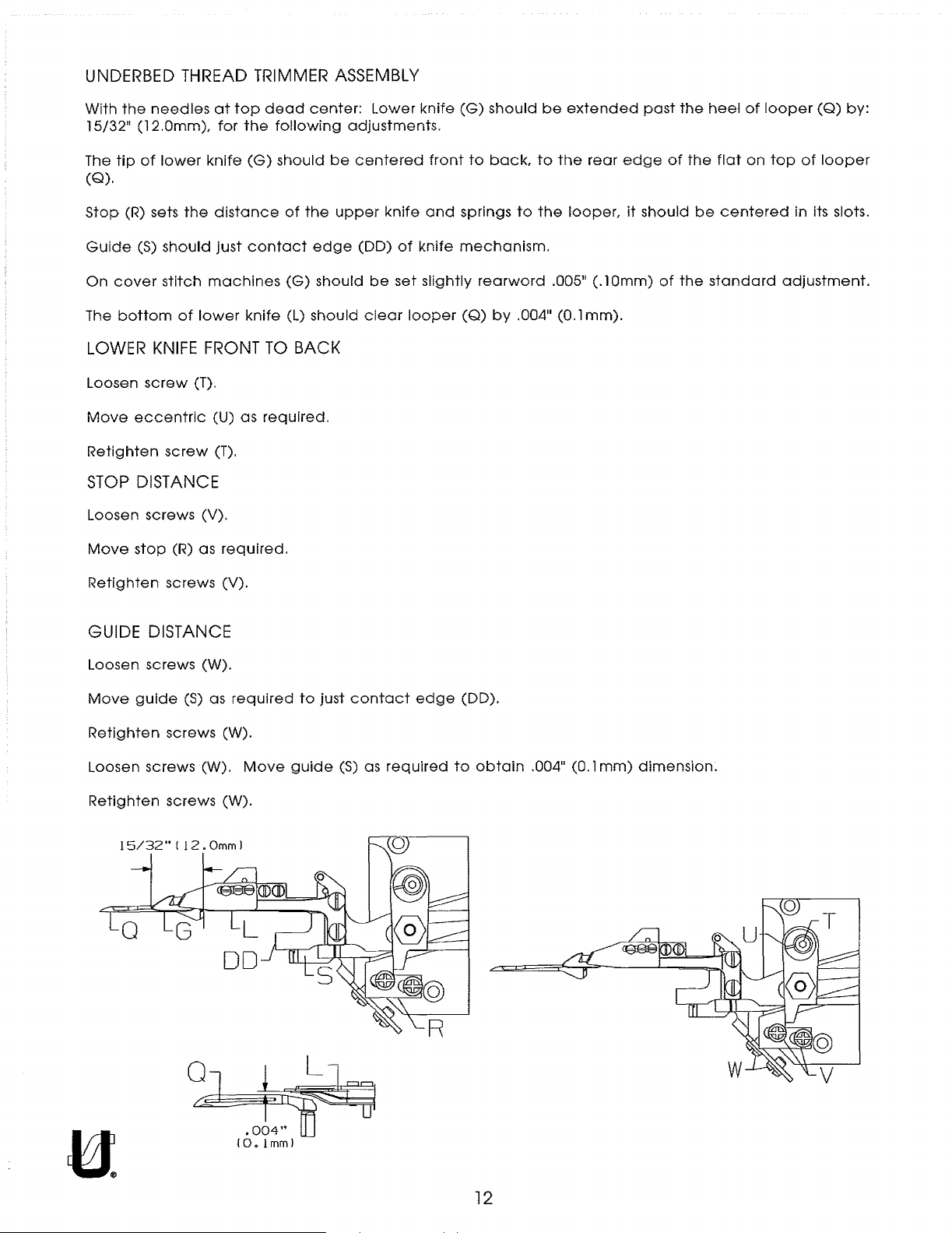
UNDERBED
From the library of: Superior Sewing Machine & Supply LLC
With
the
needles
11
15/32
The
(Q).
Stop
(12.0mm),
tip
of
(R) sets
lower
THREAD
at
top
for
knife
the
distance
TRIMMER
dead
the
following
(G)
should
of
ASSEMBLY
center:
adjustments.
be
the
upper
Lower
centered
knife
knife
front
and
(G)
should
to
back,
springs
to
be
extended
to
the
the
rear
looper,
past
edge
it
should
of
the
the
heel
flat
be
centered
of
on
looper
top
of
in its slots.
(Q)
by:
looper
Guide
On
The
LOWER
Loosen
Move
Retighten
STOP
Loosen screws (V).
Move
Retighten
(S)
should
cover
stitch
bottom
KNIFE
screw
eccentric
screw
DISTANCE
stop
screws
of
(T).
(R)
just
machines
lower
FRONT
(U)
(T).
as
GUIDE DISTANCE
Loosen screws (W).
Move
guide
(S)
as
contact
knife
TO
as
required.
required.
(V).
required
edge
(G)
(L)
should
BACK
to
should
just
contact
(DO)
be
clear
of
set
looper
edge
knife
slightly
mechanism.
rearward
(Q)
by
.004
(DO).
.005
11
(0.1
11
(.lOmm)
mm).
of
the
standard
adjustment.
Retighten
Loosen screws (W).
Retighten
screws
screws
15/32" ( 12.
Omm
0 i
~
(W).
Move
(W).
l
10.1mml
guide
(S)
as
required
q~
to
obtain
.004
11
(0.1
mm)
dimension.
12
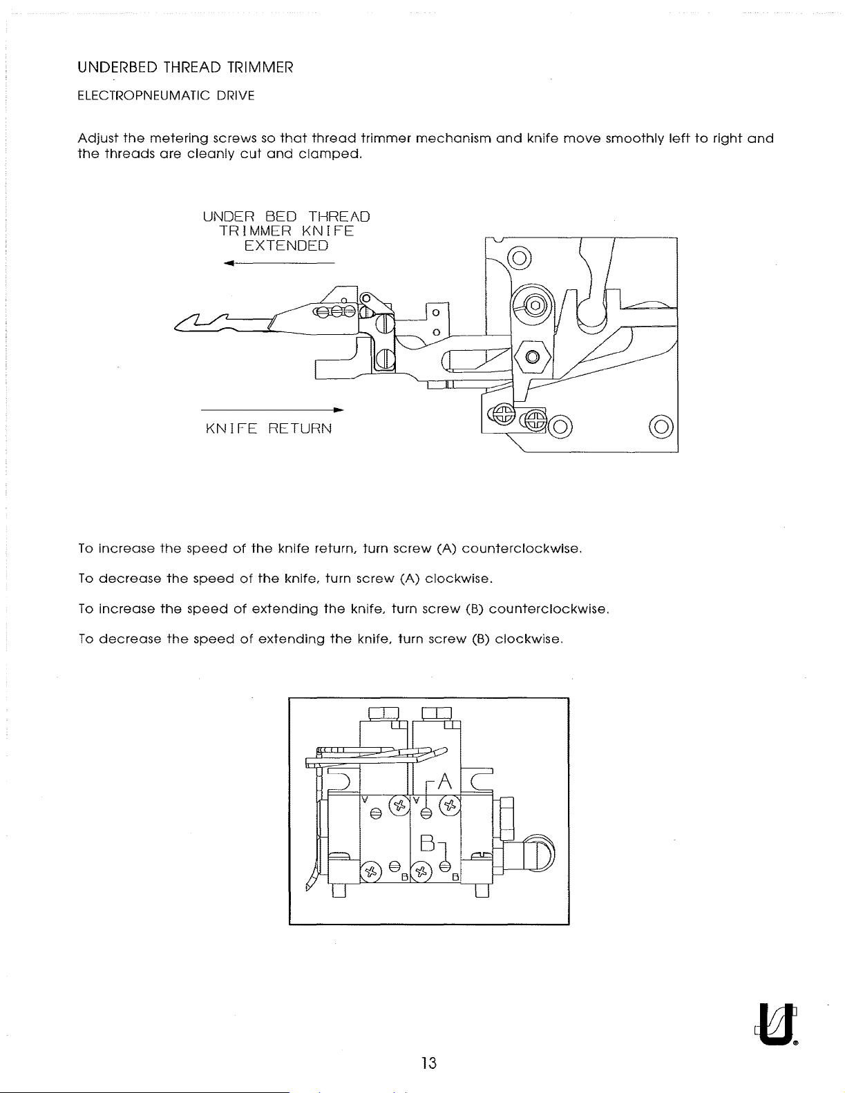
UNDERBED
From the library of: Superior Sewing Machine & Supply LLC
ELECTROPNEUMATIC DRIVE
THREAD
TRIMMER
Adjust
the
threads
the
metering
are
cleanly
screws so
cut
UNDER
TRIMMER
EXTENDED
KNIFE
that
thread
and
clamped.
BED
THREAD
KNIFE
RETURN
trimmer
mechanism
and
knife
move
smoothly
@
left
to
right
and
To
increase
To
decrease
To
increase
To
decrease
the
the
the
the
speed
speed
speed
speed
of
the
of
the
of
extending
of
extending
knife
knife,
return,
turn
the
the
turn
screw
knife,
knife,
screw
(A)
turn
turn
(A)
counterclockwise.
clockwise.
screw
screw
(B)
(B)
counterclockwise.
clockwise.
13
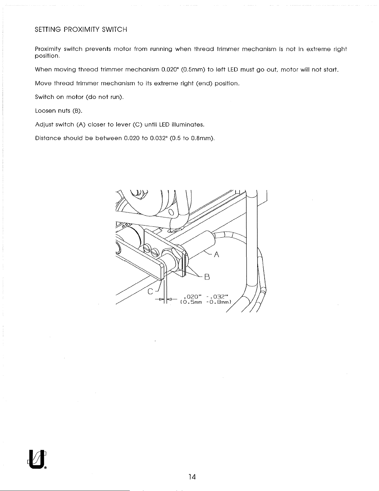
SETTING
From the library of: Superior Sewing Machine & Supply LLC
PROXIMITY
SWITCH
Proximity
switch
position.
When
Move
Switch
moving
thread
on
motor
thread
trimmer
Loosen nuts (B).
Adjust
Distance
switch
should
(A)
prevents
trimmer
mechanism
(do
not
closer
be
between
motor
run).
to
lever
from
running
mechanism
to
its
(C)
until
0.020
to
0.032
0.020
extreme
LED
illuminates.
11
(0.5
when
11
(0.5mm)
right
to
thread
to
(end)
0.8mm)
trimmer
left
LED
position.
.
mechanism
must
go
out
is
not
motor
in
extreme
will
not
right
start.
.
020"
(0.5mm
14
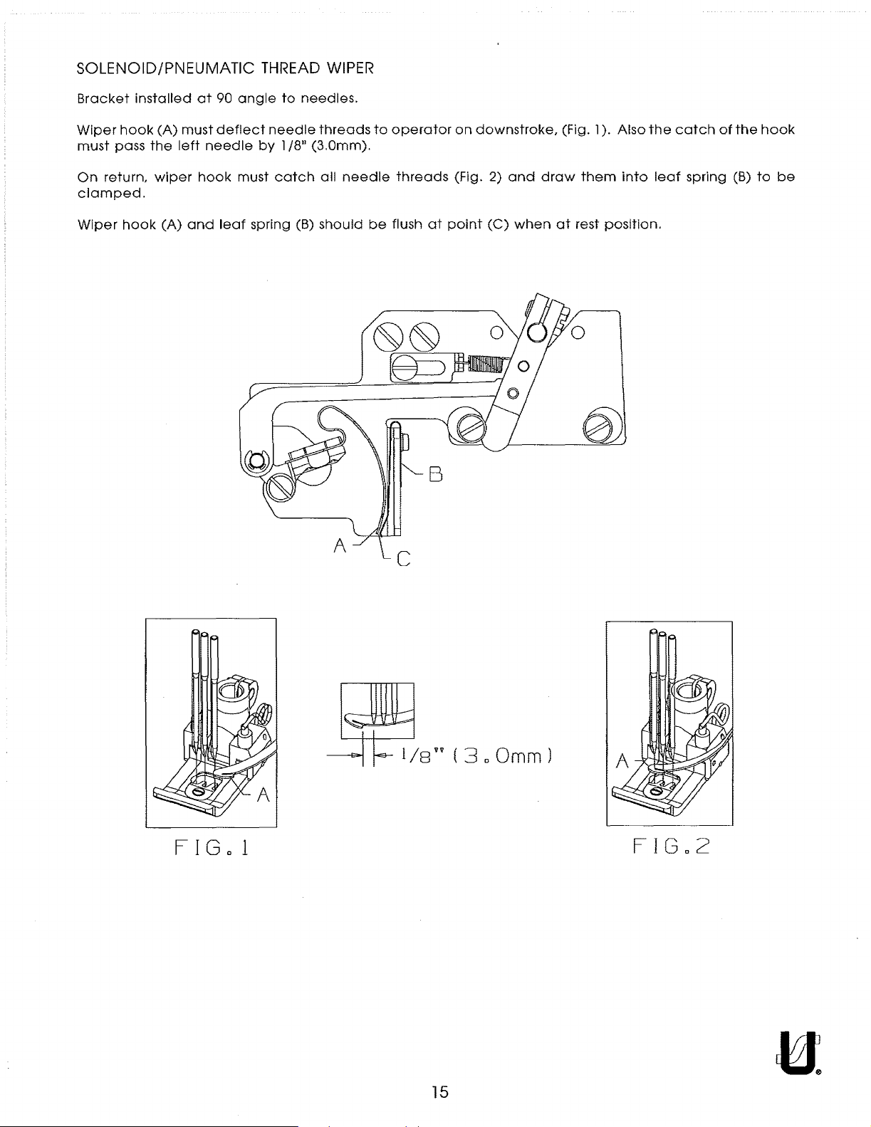
SOLENOID/PNEUMATIC
From the library of: Superior Sewing Machine & Supply LLC
THREAD WIPER
Bracket
Wiper
hook
must
pass
On
return,
clamped.
Wiper
hook
installed
(A)
must
the
left
wiper
(A)
at
needle
hook
and
90
angle
deflect
must
leaf
spring (B)
to
needle
by l /8
catch
needles.
threads
11
(3.0mm).
all
needle
should
to
be
operator
threads
flush
at
B
on
downstroke,
(Fig. 2)
point
(C)
and
when
(Fig. l ). Also
draw
them
at
rest
the
into
position.
catch
leaf
of
the
spring (B)
hook
to
be
FIG
Jf,t
o 1
..
(
3.0mm)
15
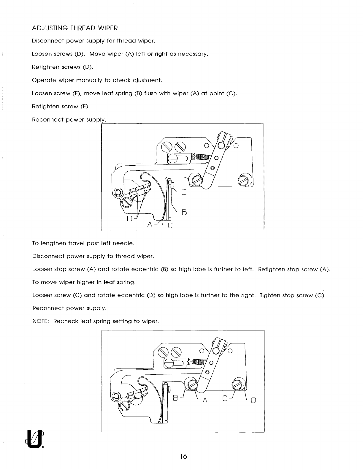
ADJUSTING THREAD WIPER
From the library of: Superior Sewing Machine & Supply LLC
Disconnect
Loosen screws (D).
Retighten
Operate
Loosen
Retighten
Reconnect
power
screws (D).
wiper
screw
(E),
screw
power
manually
(E).
supply
move
supply.
for
thread
Move
wiper
to
check
leaf
spring
r-----------------------------------------~
wiper.
(A)
left
ajustment.
(B) flush
or
right
with
as
necessary.
wiper
(A)
at
point
(C).
To
lengthen
Disconnect
Loosen
To
Loosen
Reconnect
NOTE:
stop
move
screw
Recheck
travel
power
screw
wiper
power
higher
(C)
leaf
past
supply
(A)
in
and
supply.
spring
left
to
and
leaf
rotate
needle.
thread
rotate
spring.
eccentric
setting
wiper.
eccentric
(D)
to
wiper.
(B) so
so
high
high
lobe
lobe
is
further
is
further
to
to
the
left.
right.
0
Retighten
Tighten
stop
stop
screw
screw
(A).
(C).
16
 Loading...