


Color profile: Disabled
Composite Default screen
®
MC535
VHF Marine Radio
Operating Guide
C:\MANUALS7\mc535\Mc535.vp
Tue Sep 08 10:53:55 1998

Color profile: Disabled
Composite Default screen
Maritime Radio Services Operation
You are required to comply with the Rules and Regulations set forth by the Federal Communications Commission. A complete set of FCC Marine Radio Rules may be purchased from the US Government Printing Office by requesting “Volume IV of the FCC Rules.” Some of the important rules follow:
∙You must obtain a Ship’s Station License by making application to the FCC on FCC Form 506. A copy of this form is included with your radio. An Interim Ship’s Station License may be obtained by personal appearance at your local FCC Field Office. The Ship’s Station License must be posted at the station location.
∙A Restricted Radiotelephone Operator Permit (or higher grade license) must also be obtained from the FCC in order to legally operate your transmitter in international waters. Application is to be made on FCC Form 753. An interim permit is automatically granted upon submission of your application.
∙You must keep a current copy of the appropriate FCC Rules.
∙You must maintain a log book in which you record all calls and full transmitter maintenance records.
∙Your transmitter must be verified to be in compliance with current FCC requirements by an appropriately licensed technician. This has been done at the factory for your MC535. A signed Certificate of Compliance Card is included with your radio and should be kept with your log book.
∙You may not make transmitter tuning adjustments unless you are the holder of a valid first or second class commercial license issued by the FCC. Please request the assistance of your Uniden Marine Dealer and your nearest FCC Field Office if you need other than a Ship’s Station License.
C:\MANUALS7\mc535\Mc535.vp
Tue Sep 08 10:53:57 1998
Color profile: Disabled
Composite Default screen
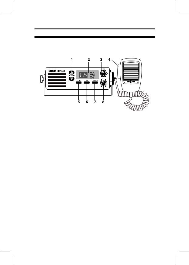
Controls and Indicators
Controls
1.UP/DWN Channel Selectors − These controls are used to select the desired communication channel.
2.LED Panel − Indicators for Channel Number, 16, INT, 1W and TX.
3.SQ (Squelch) − Eliminates the background noise when no signal is being received.
4.Push-to-Talk (PTT) Switch − Press to transmit and release to receive.
5.CH16 − Controls access to instant Channel 16 communications.
6.INT (USA/International) − Switches operation between US and International Channels.
7.1W/25W(TX Output) − Controls transmitter’s output power.
8.VOL (On/Off/Volume) − Turns the MC535 power on or off and adjusts the volume.
C:\MANUALS7\mc535\Mc535.vp
Tue Sep 08 10:53:58 1998
Color profile: Disabled
Composite Default screen
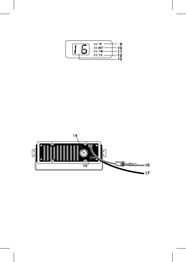
Indicators
9.16 − Indicates that Channel 16 is selected.
10.INT − Indicates International Channel Mode.
11.1W − Indicates transmitted output is 1 Watt.
12.TX (Transmit) − Indicates PTT switch is pressed and radio is transmitting.
13.LED Numerical Channel Display − Indicates Channel Number in use. Weather Channels are displayed as single digits (Example: 0, 1, 2, 3, etc.). Communication Channels are displayed as two digits (Example: 01, 02, 03, etc.).
Rear Panel Connectors
14.Antenna Connector − Connect the antenna here using a PL259 type connector.
15.Remote Speaker Connector − An external 4 ohm, 4 watt speaker may be connected to this jack. The connecting wire must use the included 3.5mm miniature plug.
16.DC Power Cord with In-line Fuse Holder − Connect red power lead to positive power source.
17.DC Ground Cord − Connect black power lead to negative power source.
C:\MANUALS7\mc535\Mc535.vp
Tue Sep 08 10:53:55 1998

Color profile: Disabled
Composite Default screen
Table of Contents
Controls and Indicators . . . . . . . . . . . . . . . . . Front Cover Foldout
Introduction . . . . . . . . . . . . . . . . . . . . . . . . . . . . . . . . . . . . . . . . . 2
Features. . . . . . . . . . . . . . . . . . . . . . . . . . . . . . . . . . . . . . . . . . 2
Included with your MC535 . . . . . . . . . . . . . . . . . . . . . . . . . . . . . . 3
Installation . . . . . . . . . . . . . . . . . . . . . . . . . . . . . . . . . . . . . . . . . . 4
Selecting a Location . . . . . . . . . . . . . . . . . . . . . . . . . . . . . . . . 4
Antenna Considerations . . . . . . . . . . . . . . . . . . . . . . . . . . . . . 4
Engine Noise Suppression . . . . . . . . . . . . . . . . . . . . . . . . . . . 5
Installing the MC535 . . . . . . . . . . . . . . . . . . . . . . . . . . . . . . . . 5
Operation . . . . . . . . . . . . . . . . . . . . . . . . . . . . . . . . . . . . . . . . . . . 6
Setting the Squelch . . . . . . . . . . . . . . . . . . . . . . . . . . . . . . . . . 6
Selecting a Channel. . . . . . . . . . . . . . . . . . . . . . . . . . . . . . . . . 7
Channel Auto Repeat . . . . . . . . . . . . . . . . . . . . . . . . . . . . . . . 7
Instant Channel 16 Communications. . . . . . . . . . . . . . . . . . . . 8
USA/INT Channels . . . . . . . . . . . . . . . . . . . . . . . . . . . . . . . . . 8
Transmitting . . . . . . . . . . . . . . . . . . . . . . . . . . . . . . . . . . . . . . . 9
Troubleshooting . . . . . . . . . . . . . . . . . . . . . . . . . . . . . . . . . . . . . 11
Care and Maintenance . . . . . . . . . . . . . . . . . . . . . . . . . . . . . . . . 12
Replacement Parts . . . . . . . . . . . . . . . . . . . . . . . . . . . . . . . . . . . 13
Service. . . . . . . . . . . . . . . . . . . . . . . . . . . . . . . . . . . . . . . . . . . . . 14
Specifications . . . . . . . . . . . . . . . . . . . . . . . . . . . . . . . . . . . . . . . 15
USA/INT Frequency Lists . . . . . . . . . . . . . . . . Rear Cover Foldout
1
C:\MANUALS7\mc535\Mc535.vp
Tue Sep 08 10:53:44 1998

Color profile: Disabled
Composite Default screen
Introduction
The Uniden MC535 VHF marine radio transceiver is designed to provide you with years of trouble-free service. It’s rugged components and materials are easily capable of withstanding the harsh marine environment. The transceiver has a splashproof housing to protect the electronics, and the unit may be mounted in several convenient locations on-board your vessel using the universal mounting bracket.
You can be confident in your choice of radio equipment because the MC535 offers Instant Channel 16 access, automatic transmitter time-out, and complete coverage of the marine frequency band. It will meet your communication needs by providing you with state-of-the-art radio electronics that are easy to operate.
We are certain that you will enjoy your MC535. To ensure that you get the most from its features, please read this operating guide carefully before using the unit.
Features
∙ Receives 90 Marine Channels |
∙ Receives 10 Weather Channels |
∙ 1W/25W Transmitter |
∙ Transmits 55 Marine Channels |
∙ Instant Channel 16 Button |
∙ External Speaker Jack |
∙ 5 Minute Transmitter Time-Out |
∙ Splash Proof Chassis |
∙ USA/INT Frequency Capable |
∙ Channel Auto Repeat |
Specifications, Features, and availability of Optional Accessories are all subject to change without prior notice.
2
C:\MANUALS7\mc535\Mc535.vp
Tue Sep 08 10:53:44 1998

Color profile: Disabled
Composite Default screen
Included with your MC535
MC535 Owners Manual |
|
Microphone Hanger and |
OMMC535 |
|
Screws |
|
|
MH635 |
|
|
|
|
|
|
Other Printed Material
Mounting Bracket and |
3.5mm Mini Plug |
Knobs |
ESP635 |
MB635 |
and Spare Fuse |
3
C:\MANUALS7\mc535\Mc535.vp
Tue Sep 08 10:53:46 1998
 Loading...