


Maritime Radio Services Operation
Warning!
This transmitter will operate on channels/frequencies that have restricted use in the United States. The channel assignments include frequencies assigned for exclusive use of the U.S.
Coast Guard, use in Canada, and use in international waters. Operation in these frequencies without proper authorization is strictly forbidden. For frequencies/channels that are currently for use in the U.S. without an individual license, please contact the FCC Call Center at 1-888-CALL-FCC.
For individuals requiring a license, such as commercial users, you should obtain a license application from your nearest FCC field office.
Uniden works to reduce lead content in our PVC coated cords in our products and accessories.
WARNING: The cords on this product and/or accessories contain lead, a chemical known to the State of California to cause birth defects or other reproductive harm. Wash hands after handling.

Contents |
|
Uniden SOLARA DSC ............................................................................ |
2 |
Included with your SOLARA DSC .......................................................... |
3 |
Controls and Indicators........................................................................... |
4 |
Installation............................................................................................... |
7 |
Choosing a Location.......................................................................... |
7 |
Engine Noise Suppression ................................................................ |
8 |
Antenna Considerations .................................................................... |
8 |
Antenna Selection and Installation .................................................... |
8 |
Installing the SOLARA DSC .............................................................. |
9 |
Operation .............................................................................................. |
10 |
Power On/Off................................................................................... |
10 |
Last Channel Memory ..................................................................... |
10 |
Squelch ............................................................................................ |
11 |
Coast Guard Channel 16/Channel 9 Communications ................... |
12 |
Selecting a Channel ........................................................................ |
12 |
Weather Channels .......................................................................... |
12 |
All Channel Scan............................................................................. |
13 |
Weather Alert................................................................................... |
13 |
Setting the Transmit (TX) Power ..................................................... |
14 |
Recommended Emergency Broadcast Instructions ........................ |
15 |
Distress............................................................................................ |
16 |
Digital Selective Calling (DSC)........................................................ |
17 |
Individual .................................................................................... |
17 |
All Ships ..................................................................................... |
18 |
User MMSI....................................................................................... |
20 |
NMEA Technical Setup ......................................................................... |
21 |
Optional Accessories ............................................................................ |
21 |
VHF FM Marine Radio Telephone |
|
Channel and Functions (USA Channels) ........................................ |
22 |
Channel and Functions (International Channels) ........................... |
23 |
Channel and Functions (Canadian Channels)................................ |
24 |
Specification ......................................................................................... |
25 |
Troubleshooting .................................................................................... |
26 |
Care and Maintenance ......................................................................... |
27 |
Three Years Limited Warranty .............................................................. |
29 |

Uniden SOLARA DSC
The Uniden SOLARA DSC VHF marine radio has been designed to give you a rugged, reliable instrument that will provide you with years of trouble-free service.
With proper care and maintenance, your marine radio could outlast your present vessel and serve you well on-board. The full features and flexibility designed into this quality transceiver will prevent it from becoming obsolete regardless of changes in craft or geographic locations.
The technical excellence of this marine radio is demonstrated by the multiplicity of uses for which it has been found acceptable by the U.S. Federal Communications Commission. It is acceptable for compulsory use on "party boats", for use on vessels subject to the Great Lakes Radio Agreement or bridge-to-bridge requirements, for general pleasure and commercial vessels, and certain land stations in marine service.
The SOLARA DSC is of all solid-state design with conservatively rated, rugged components and materials compatible with the marine environment. The transceiver utilizes a number of gaskets, sealing rings, waterproof membranes, and other sealants to effect a waterproof housing for protection of the electronics. It meets the most stringent JIS7 waterproof specification. The unit may be mounted in any number of convenient locations on your vessel by utilizing the optional flash mount bracket (White - FMB322W, Black - FMB322B).
You are encouraged to thoroughly read the rest of this Operating Guide to acquaint yourself with the characteristics and operation of your transceiver so that you can contribute to the longevity of your investment.
Keep your receipt as proof-of-purchase in case warranty service is required.
Features, specifications, and availability of optional accessories are all subject to change without notice.
Note: SOLARA DSC meets JIS7 requirements.
The color of your SOLARA DSC may vary.
2
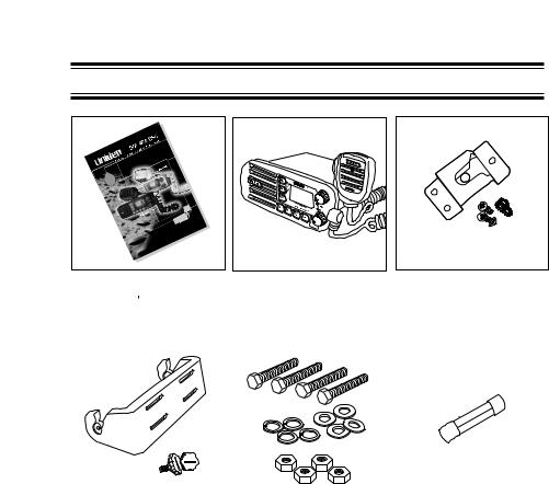
Included with your SOLARA DSC
SOLARA DSC |
SOLARA DSC Radio |
|
Microphone Hanger |
|
Owner s Manual |
|
|
and Screws |
|
|
|
|
|
|
|
|
|
|
|
Mounting Bracket |
Mounting Hardware |
Spare Fuse |
and Knobs |
|
250V 6A |
3
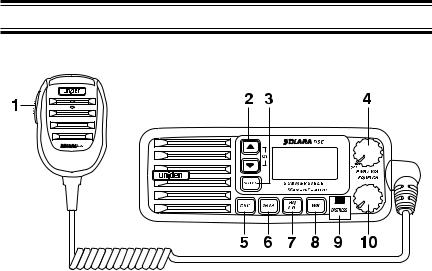
Controls and Indicators
Front panel/Microphone
1.PTT Switch - Press to transmit and release to receive.
2.CHANNEL/▲/▼- These keys are used to change the channel number up/down. These buttons are also used to move the cursor in DSC Menu mode.
3.SELECT - In the DSC Menu mode this is used to select the DSC menu options.
4.PWR/VOL (On/Off/Volume) - Turns the unit On or Off and adjusts the speaker volume.
5.DSC - Press this key to activate DSC Menu mode.
6.16/9 - Press this key instantly change to Channel 16, Channel 9 or current channel.
7.HI/LO/SCAN/UIC - Press this key to change the transmit power to either High or Low. Press and hold this key for 2 seconds to place the radio into the Scan mode. Press both HI/LO/SCAN/UIC and WX/ALERT/UIC at the same time to change channel modes from USA to INTERNATIONAL to CANADIAN.
8.WX/ALERT/UIC - Press this key to listen to active NOAA Weather channels. Press and hold this key for 2 seconds to place the radio into the Weather Alert mode. Press both HI/LO/SCAN/UIC and WX/ALERT/UIC at the same time to change channel modes from USA to INTERNATIONAL to CANADIAN.
9.DISTRESS - Press this key to send a signal of distress in case of emergency.
10.SQUELCH - Rotate this knob eliminate background noise when a signal is not being received.
4
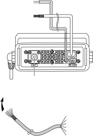
Rear Panel Connectors
1 |
1. |
DC Cord |
|
2. |
ACC Cable |
2 |
3. |
Antenna Connector |
|
|
3
ACC Cable
Thick Black : DC GND
Orange |
: External Speaker (+) |
Black |
: External Speaker (—) GND |
Green |
: GPS DATA IN |
Brown |
: GPS GND |
Yellow |
: NC |
5
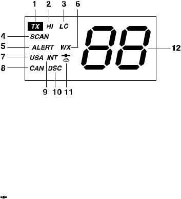
1.TX (Transmit) - Indicates transmitting.
2.HI (High) - Indicates transmit output is 25 Watts.
3.LO (Low) - Indicates transmit output is 1 Watt.
4.SCAN - Indicates Scan Mode has been activated.
5.ALERT - Indicates Weather Alert Mode has been activated.
6.WX - Indicate Weather Channel Mode has been activated.
7.USA - Indicates US Channel Mode.
8.CAN - Indicates Canada Channel Mode.
9.INT - Indicates International Channel Mode.
10.DSC - Indicators the radio is in the DSC mode.
11. (GPS Icon) - It appears while GPS module is receiving the data.
12.Channel Display - Indicates Channel Number in use.
6

Installation
Caution: The SOLARA DSC will only operate with a nominal 13.8 volt negative ground battery system.
It is important to carefully determine the most suitable location for your radio on your vessel. Electrical, mechanical, and environmental considerations must all be taken into account. You should select the optimum relationship among these considerations.
Keep in mind the flexibility designed into the SOLARA DSC so that you can most conveniently use it. Features which should be considered are:
1.The universal mounting bracket may be installed on either the top or bottom of a shelf, on a bulkhead, or for overhead mounting.
2.The REMOTE speaker wires can be used with an auxiliary speaker.
3.Front fire internal speaker allows convenient in-dash mounting using the optional bracket.
Choosing a Location
Some important factors to consider in selecting the location for your
SOLARA DSC.
1.Select a location that is free from spray and splash.
2.Keep the battery leads as short as possible. Direct connection to the battery is most desirable. If direct connection can not be made with the supplied power lead, any extension should be made with #10 AWG wire. Long extensions should use larger gauge wire.
3.Keep the antenna lead as short as possible. Long antenna leads can cause substantial loss of performance for both receiving and transmitting.
4.Locate your antenna as high as possible and clear from metal objects. The reliable range of coverage is a direct function of the antenna height.
5.Select a location that allows free air flow around the heat sink on the rear of the radio.
6.Select a location well away from the ship’s compass. Auxiliary speakers also should be located away from the compass.
7
Engine Noise Suppression
Interference from the noise generated by the electrical systems of engines is sometimes a problem with radios. The SOLARA DSC has been designed to be essentially impervious to ignition noise and alternator noise. However, in some installations it may be necessary to take measures to further reduce the effect of noise interference. All DC battery wires, antenna lead, and accessory cables should be routed away from the engine and engine compartment, and from power cabling carrying high currents.
In severe cases of noise interference, it may be necessary to install a noise suppression kit. Contact your Uniden Dealer for more information.
Antenna Considerations
A variety of antennas are available from a number of quality suppliers. It is recommended you draw upon the advice of your Uniden dealer in determining a suitable antenna for your vessel and range requirements.
In general, communication range is increased by using a high-gain antenna placed as high as possible above the water line. Antennas should be located away from metal objects. Antennas should not have excessively long coaxial feed cables.
Antenna Selection and Installation
SOLARA DSC has been designed to accomodate all of the popular marine VHF antennas. However, the selection and the installation of the antenna is the responsibility of the user or installer.
The FCC has determined that excessive radiation poses a health risk to people near radio transmitting antennas. Therefore, the antenna used with this radio should be installed using the following guidelines to insure a suitable distance between the antenna and persons close by.
Small whip antennas (3 dB) or smaller should be installed keeping at least three feet separation distance between the radiating element and people.
Larger antennas (6 dB or 9 dB) should be installed keeping at least a six feet separation distance.
No person should touch the antenna or come into the separation distance when the radio is transmitting.
8
 Loading...