


HIGH CURRENT POWER
AMPLIFIERS
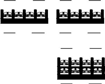
UHC5
1 X 150 + 4 X 60W RMS
5 CHANNEL AMPLIFIER
UHC4
4 X 60W RMS
4 CHANNEL AMPLIFIER
UHC2
2 X 60W RMS
2 CHANNEL AMPLIFIER
ULTIMATE®
138 University Parkway
Pomona, CA 91768
Toll Free: 888-909-9988
Telephone: 909-594-2604
Fax: 909-594-0191
INTRODUCTION
I. Description
This device is a high power, audio amplifier. Use it responsibly. Very loud music can cause permanent hearing loss. This amplifier is intended for installation in vehicles with a 12-Volt, negative ground electrical system. Attempting to connect or operate the amplifier in another type of electrical system may cause damage to the amplifier or the electrical system.
II. About This Manual
Read the Instructions-
Be sure that you have read all operating instructions and understand all safety precautions before installing and operating the amplifier. We recommend that you have your UHC amplifier installed by a specialist.
Follow the Instructions-
The instructions are intended to help you safely obtain the best performance from the amplifier. Carefully follow all installation and operating instructions.
Save the Operating Manual-
Keep the manual in a safe place after installing the amplifier. You may have questions later.
Text Conventions used in this ManualBold-
Headings and important information.
Bold, Underlined-
Very important information.
"Bold"-
As labeled on the amplifier, or quoted from elsewhere in this manual.
III. Safety and Operating Precautions-
Caution!
This symbol warns the user of a potential risk or hazard if instructions are not followed.
ÞThis arrow symbol points to a specific instruction for avoiding a potential hazard.
ii

1. Installation
1.1InstallationMounting the Amplifier
Step 1- Disconnect the negative (-) battery cable before mounting the amplifier or making any connections. Check the battery and alternator ground (-) connections. Make sure they are properly connected and free of corrosion
Step 2- Choose a mounting location for your amplifier. Find a location on a flat surface away from heat and moisture. Be sure the mounting location and the drilling of pilot holes for mounting will not present a hazard to any wires, control cables, fuel lines, fuel tanks, hydraulic lines, or other vehicle systems or components. Common mounting locations are under the front passenger seat, or in the trunk area. Choose a location with unimpaired air circulation. The amplifier will dissipate heat more efficiently if mounted vertically.
Step 3- Use the supplied screws and rubber bushings. Press the rubber bushings into the mounting holes at each end of the amplifier. Place the amplifier in the mounting location, and mark the positions of the holes with a marker, pen or pencil. Carefully drill the mounting holes in the marked positions.
Caution!
Þ Check carefully before drilling any pilot holes.
Step 4- Use the supplied mounting screws to securely fasten the amplifier to the mounting surface.
1
Step 5- Use the supplied Allen head screws to mount the end caps to the ends of the main heat sink.
Step 6- Use the supplied screws to attach the end caps to the mounting surface.
Caution!
ÞMake sure to mount the amplifier using the supplied screws and rubber bushings. Do not mount the amplifier by the end caps alone.
1.2InstallationPower Connections
Step 1- Run a power cable from the battery to the amplifier mounting location. Use rubber grommets to protect the cable anywhere it has to go through metal.
UHC5, UHC4 - Use #4 AWG or larger power and ground cable. UHC2 - Use #8 AWG or larger power and ground cable.
Step 2- Connect one end of an in-line fuse holder to the power cable. Connect the other end of the fuse holder to the positive battery post with 20 cm (or less) of the same cable. This fuse location will protect the system and the vehicle against the possibility of a short circuit in the power cable. Be sure to use a fuse and fuse holder adequate for the application. Do not place a fuse in the holder at this time. The fuse rating is depending on the powerand ground cable size. The maximum fuse rating for each amplifier in the UHC series is:
UHC5 - 80 Amp |
UHC4 - 80 Amp |
UHC2 - 40 Amp |
Caution!
ÞBridging fuses or replacing a fuse with one of a higher rating may cause damage to the amplifier and the vehicle's electrical system.
Step 3- Run a remote turn on cable from the switched +12V source you will be using to turn on the system components. This may be a toggle switch, a relay, or your source unit’s remote trigger wire, or power antenna trigger wire. Run this lead to the amplifier mounting location. Use #18 AWG wire or larger.
Step 4- Locate a secure grounding connection as close to the amplifier as possible. Make sure the location is clean and provides a direct electrical connection to the frame of the vehicle. Connect one end of a short piece of the same size cable as the power cable to the grounding point. Run the other end of the cable to the amplifier mounting location.
Step 5- connect the ground cable to the screw terminal labeled
“POWER, (GND)”.
Step 6- Connect the power cable to the amplifier at the screw terminal labeled “POWER, +12V”.
2
Step 7- Connect the remote turn on cable to the screw terminal labeled
“POWER, (REM)”.
1.3InstallationSpeaker Connections
Step 1- Run #16 AWG or larger connecting wire from your speakers to the amplifier mounting location. Keep speaker wires away from power cables and amplifier input cables. Use grommets anywhere the wires have to pass through holes in the metal frame or sheet metal. Connect to the speakers according to the type of terminals on each speaker.
Step 2- Strip 3/8" of insulation from the end of each wire and twist the wire strands together tightly. Make sure there are no stray strands that might touch other wires or terminals and cause a short circuit.
Step 3- Crimp spade lugs over the wire ends or tin the ends with solder to provide a secure termination.
Step 4- Connect the wire ends to your amplifier as follows:
UHC5, UHC4- "FRONT" and "REAR" SPEAKER
TERMINALS
FRONT |
UHC4 |
|
REAR |
SPEAKER |
|
|
SPEAKER |
(L+) (L-) (R+) |
(R-) |
(L+) |
(L-) (R+) (R-) |
( + ) |
( - ) |
( + ) |
( - ) |
BRIDGE |
|
|
BRIDGE |
Follow the left, (L+) (L-), and right, (R+) (R-), channel and polarity markings, making sure they match the channel and polarity of the connections at the speakers.
UHC5
SPEAKER
(L+) (L-) (R+) (R-)
FRONT |
REAR
BRIDGE
( + ) |
( - ) |
3
 Loading...