


INSTRUCTION MANUAL
DM383B
1-800-547-5740 • Fax: (503) 643-6322 www.ueitest.com • email: info@ueitest.com
Introduction
The DM383B is a handheld, battery powered digital multimeter that is designed to meet IEC 1010-1 (EN 61010-1), standards, the EMC directive, and other safety standards (see “Specifications”). It will measure up to 1000 volts DC and 750 Volts AC in a CAT II environment and up to 600 volts AC and DC in a CAT III environment.
Features include
•750 volts AC and 1000 Volts DC
•10 Amps AC and DC
•Resistance to 40 Megohms
•Diode check function
•Continuity
•3 3/4" digit, 4000 count display
•Max capture mode
•Data hold
•On-screen range and function indicators
•CE listed CAT III
Safety Notes
Before using this meter, read all safety information carefully. In this manual the word "WARNING" is used to indicate conditions or actions that may pose physical hazards to the user. The word "CAUTION" is used to indicate conditions or actions that may damage this instrument.
•Do not attempt to measure any voltage that exceeds the category based rating of this meter
•Do not attempt to use this meter if either the meter or the test leads have been damaged. Turn it in for repair at a qualified repair facility
•Ensure meter leads are fully seated by making a quick continuity check of the leads prior to making voltage measurements
•Keep your fingers away from the test lead’s metal probe
contacts when making measurements. Always grip the leads behind the finger guards molded into the probes
•Use a current clamp adapter when measuring current that may
exceed 10 amps. See the accessories in UEi’s full-line ca t a l o g
•Do not open the meter to replace batteries or fuses while the probes are connected
 WARNING!
Exceeding the specified limits of this meter is dangerous and can expose the user to serious or possibly fatal injury.
•Voltages above 60 volts DC or 25 volts AC may constitute a serious shock hazard
•Always turn off power to a circuit (or assembly) under test before cutting, unsoldering, or breaking the current path - Even small amounts of current can be dangerous
•Always disconnect the live test lead before disconnecting the common test lead from a circuit
•In the event of electrical shock, ALWAYS bring the victim to the emergency room for evaluation, regardless of the victim’s
apparent recovery - Electrical shock can cause an unstable heart rhythm that may need medical attention
•Higher voltages and currents require greater awareness of physical safety hazards - Before connecting the test leads; turn off power to the circuit under test; set the meter to the desired function and range; connect the test leads to the meter first, then to the circuit under test. Reapply power
•If any of the following indications occur during testing, turn
off the power source to the circuit under test:
•Arcing
•Flame
•Smoke
•Extreme Heat
•Smell of Burning Materials
•Discoloration or Melting of Components
 CAUTION!
Do not attempt to re m ove the meter leads from the circuit under test. The leads, the meter, or the circuit under test may have degraded to the point that they no longer provide protection from the voltage and c u r rent applied. If any of these erroneous readings are observed,
disconnect power immediately and recheck all settings and connections.
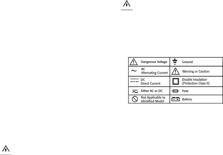
International Symbols
Controls and Indicators
1.Digital Display: Readings are displayed on a digital, 4000 count display, which includes the appropriate polarity
indication, the range and function icons, and shows the decimal point position for the selected range. (See Display Icons).
2.Power Push-button: Used to turn the power to the meter on or off.
3.MAX Push-button: Causes the meter to record and display the
maximum value of any function selected. The word “MAX” appears in the upper right of the LCD. This feature resets only when the push-button is pressed a second time, not when the selector is moved.
4.Hold Push-button: Freezes the reading presently on the digital display, and displays the words “DATA HOL D ” on the left side of the LCD. To cancel data hold, press the “DATA HOL D ” b u t t o n again. This feature resets only when the push-button is pressed a second time, not when the selector is moved.
5.Rotary Switch: A l l ows you to switch between any of the functions or values indicated by the numbers, icons, and group outlines printed around the rotating dial.
DM383B-MAN |
P. 1 |
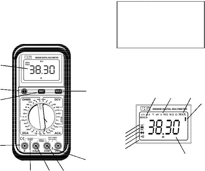
6.10 Amp, Fused, Meter Lead Terminal: Use this input terminal (port) when measuring amps greater than 400 mA, but less than 10 Amps AC or DC. Use caution when selecting a m p e rage measurements on the rotary dial. Remember
a m p e rage measurements are made in series with your circuit.
7.This Symbol Reminds the User to Follow Provided Instructions: See “Caution” in the international symbol section of this manual.
8.Microamp/Milliamp Input Terminal: The red test lead is plugged into this terminal when measuring current (AC or DC) in the 400 mA and below ra n g e .
9.Common Terminal: The black test lead is plugged into this terminal, and supplies the ground or “low” reference for all m e a s u r e m e n t s .
10."Flash" Symbol: Warns operators that potentially dangerous voltages may be present. Use caution when making high-voltage measurements.
11.Multifunctional Terminal Information: I n d i cates the
m aximum input values and category ratings established by IEC 1010 - 1.
12.Multifunctional (Volts, Ohms, and Diode Test) Input Terminal: Use the red test lead in this terminal for any of these test functions.
1
2
4
3
 5
5
 11
11
6 |
|
12 |
|
10
7 |
8 |
9 |
LCD Display Functional Description
1.Indicates that the audible continuity mode has been selected.
2.Indicates that diode testing has been selected.
3.Indicates the meter is reading DC voltage or current.
4.Indicates a negative polarity measurement. (Applicable to DC functions).
5.Indicates the meter is reading AC voltage or current.
6.Indicates that HOLD has been selected and the display is no longer updating numerical data.
7.Indicates MAX push-button is pressed and the meter is displaying the maximum numerical value recorded in any mode from the time the button was pressed.
8.The following symbols represent the type and value of measurement being made.
|
Symbol |
Function or Value |
|
|
V |
Volts |
|
|
A |
Amps |
|
|
! |
Ohms (Resistance Value) |
|
|
M |
1 |
Meg = 1,000,000 |
|
K |
1 |
Kilo = 1,000 |
|
m |
1 |
Milli = 0.001 |
µ |
1 |
Micro = 0.000001 |
|
9.I n d i cates the battery is low and must be changed immediately
10.Indicates measured numerical values
NOTE: When OL is displayed on the LCD, it indicates the value measured exceeds the limits of the selected range, or exceeds the over-all limits of the meter.
6 |
8 |
7 |
9
5
4
3
2
1
10
DM383B-MAN |
P. 2 |
 Loading...