


 Loading...
VAF4 TRANSMIG
Wire feeder
Art # A-11251_AB
Operating Manual
Revision: AC |
Issue Date: December 3, 2012 |
Manual No.: 0-5231 |
|||||||||||||
Operating Features: |
|
|
|
|
|
|
|
|
|
|
|
|
|
|
|
|
|
|
|
|
|
|
|
|
|
|
|
|
|
|
|
|
|
|
|
|
|
|
|
|
|
|
|
|
|
|
|
|
|
|
|
42/115 |
|
50Hz |
|
|
|
. |
|
|
|
|
|
|
|
|
|
|
|
60 |
|
|
|
|
|
I |
|
|
|
|
|
|
|
|
|
|
|
|
|
|
|
|
|
|
|

WE APPRECIATE YOUR BUSINESS!
Congratulations on your new Cigweld product. We are proud to have you as our customer and will strive to provide you with the best service and reliability in the industry. This product is backed by our extensive warranty and world-wide service network. To locate your nearest distributor or accredited service provider call +1300 654 674, or visit us on the web at www.cigweld.com.au
This Operating Manual has been designed to instruct you on the correct use and operation of your CIGWELD product. Your satisfaction with this product and its safe operation is our ultimate concern. Therefore please take the time to read the entire manual, especially the Safety Precautions. They will help you to avoid potential hazards that may exist when working with this product.
We have made every effort to provide you with accurate instructions, drawings, and photographs of the product(s) while writing this manual. However errors do occur and we apologize if there are any contained in this manual.
Due to our constant effort to bring you the best products, we may make an improvement that does not get reflected in the manual. If you are ever in doubt about what you see or read in this manual with the product you received, then check for a newer version of the manual on our website or contact our customer support for assistance.
YOU ARE IN GOOD COMPANY!
The Brand of Choice for Contractors and Fabricators Worldwide.
CIGWELD is the Market Leading Brand of Arc Welding Products for Victor Technologies International, Inc. We are a mainline supplier to major welding industry sectors in the Asia Pacific and emerging global markets including; Manufacturing, Construction, Mining, Automotive, Engineering, Rural and DIY.
We distinguish ourselves from our competition through market-leading, dependable products that have stood the test of time. We pride ourselves on technical innovation, competitive prices, excellent delivery, superior customer service and technical support, together with excellence in sales and marketing expertise.
Above all, we are committed to develop technologically advanced products to achieve a safer working environment for industry operators.

!WARNINGS
Read and understand this entire Manual and your employer’s safety practices before installing, operating, or servicing the equipment.
While the information contained in this Manual represents the Manufacturer’s best judgement, the Manufacturer assumes no liability for its use.
Operating Manual Number 0-5231 for: |
|
Cigweld Transmig VAF4 Wirefeeder |
Part Number W3000700 |
Published by: CIGWELD Pty. Ltd 71 Gower Street
Preston, Victoria, Australia, 3072 +61 3 9474 7400, +61 3 9474 7391
www.cigweld.com.au
Copyright 2012 by
Victor Technologies International, Inc.
All rights reserved.
Reproduction of this work, in whole or in part, without written permission of the publisher is prohibited.
The publisher does not assume and hereby disclaims any liability to any party for any loss or damage caused by any error or omission in this Manual, whether such error results from negligence, accident, or any other cause.
Publication Date: October 8, 2012
Revision Date: December 3, 2012
Record the following information for Warranty purposes:
Where Purchased: |
_____________________________________ |
Purchase Date: |
_____________________________________ |
Equipment Serial #: |
_____________________________________ |
TABLE OF CONTENTS
SECTION 1: GEneral Information.................................................................... |
1-1 |
|
1.01 |
Arc Welding Hazards....................................................................................... |
1-1 |
1.02 |
Principal Safety Standards.............................................................................. |
1-5 |
1.03 |
Symbol Chart................................................................................................... |
1-6 |
1.04 |
Declaration of Conformity................................................................................ |
1-7 |
SECTION 2: INTRODUCTION............................................................................... |
2-1 |
|
2.01 |
How to Use This Manual.................................................................................. |
2-1 |
2.02 |
Equipment Identification.................................................................................. |
2-1 |
2.03 |
Receipt of Equipment...................................................................................... |
2-1 |
2.04 |
Description...................................................................................................... |
2-2 |
2.05 |
User Responsibility......................................................................................... |
2-2 |
2.06 |
Transportation Methods.................................................................................. |
2-2 |
2.07 |
Packaged Items............................................................................................... |
2-2 |
2.08 |
Specifications.................................................................................................. |
2-3 |
2.09 |
Optional Accessories....................................................................................... |
2-3 |
SECTION 3: INSTALLATION, Operation AND SETUP................................................. |
3-1 |
|
3.01 |
Environment.................................................................................................... |
3-1 |
3.02 |
Location.......................................................................................................... |
3-1 |
3.03 |
Ventilation....................................................................................................... |
3-1 |
3.04 |
Mains Supply Voltage Requirements............................................................... |
3-1 |
3.05 |
Electromagnetic Compatibility......................................................................... |
3-1 |
3.06 |
Front Panel Controls, Indicators and Features................................................. |
3-3 |
3.07 |
Rear Panel Controls and Features.................................................................... |
3-8 |
3.08 |
Advanced Features Mode................................................................................ |
3-9 |
3.09 |
Wirefeeder Configuration for Different Power Sources.................................. |
3-14 |
3.10 |
Attaching the MIG Torch (Euro)..................................................................... |
3-15 |
3.11 |
Installing Handle Assembly........................................................................... |
3-15 |
3.12 |
Installing Lifting Eye Kit (Optional)................................................................ |
3-17 |
3.13 |
Installing Tweco No. 4 Adaptor (Optional)..................................................... |
3-18 |
3.14 |
Installing Wire Spool Cover (optional)........................................................... |
3-27 |
3.15 |
Installing Welding Wire Spool....................................................................... |
3-30 |
3.16 |
Wire Reel Brake............................................................................................. |
3-31 |
3.17 |
Inserting Wire into Feed Mechanism ............................................................ |
3-31 |
3.18 |
Feed Roll Pressure Adjustment..................................................................... |
3-32 |
3.19 |
Installing and Changing the Feed Roll / Removing Inlet Guide & Euro Adaptor..... |
|
|
3-33 |
|
3.20 |
Shielding Gas Regulator Operating Instructions............................................ |
3-34 |
3.21 |
Wire Feeder Set Up MIG (GMAW) Welding with Gas Shielded MIG Wire...... |
3-36 |
3.22 |
Wire Feeder Set Up MIG (GMAW) Welding with Gasless MIG Wire............... |
3-38 |
3.23 |
Prewelding Procedure................................................................................... |
3-41 |
3.24 |
Arc Signal Override (SIL_1 #2)...................................................................... |
3-41 |
3.25 |
Welding2T Operation.................................................................................. |
3-42 |
3.26 |
Spot Operation.............................................................................................. |
3-42 |
3.27 |
Welding4T Operation.................................................................................. |
3-43 |
3.28 |
Stitch Operation............................................................................................. |
3-44 |
3.29 |
PTC Protection of Power Source Contactor Control Output........................... |
3-45 |
3.30 |
Ground Fault Operation................................................................................. |
3-45 |
3.31 |
Electronic Motor Protection........................................................................... |
3-45 |
TABLE OF CONTENTS
SECTION 4: service....................................................................................... |
4-1 |
|
4.01 |
Cleaning The Unit............................................................................................ |
4-1 |
4.02 |
Cleaning The Feed Rolls.................................................................................. |
4-1 |
4.03 |
System Maintenance....................................................................................... |
4-1 |
4.04 |
Troubleshooting Guide.................................................................................... |
4-1 |
4.05 |
Error Codes and Remedies.............................................................................. |
4-2 |
4.06 |
MIG (GMAW/FCAW) Basic Welding Technique................................................ |
4-4 |
4.07 |
MIG (GMAW/FCAW) Welding Troubleshooting................................................ |
4-7 |
4.08 |
Troubleshooting............................................................................................ |
4-10 |
SECTION 5: Parts List................................................................................... |
5-1 |
|
5.01 |
Equipment Identification.................................................................................. |
5-1 |
5.02 |
How To Use This Parts List............................................................................. |
5-1 |
5.03 |
Replacement Parts (without wirefeed plate).................................................... |
5-2 |
5.04 |
Replacement PartsWirefeed Plate................................................................. |
5-3 |
Appendix 1: connection diagram................................................................... |
A-1 |
|
CIGWELD LIMITED WARRANTY......................................................................... |
RC-1 |
|
TERMS OF WARRANTY – APRIL 2012................................................................. |
RC-2 |
|
WARRANTY SCHEDULE – APRIL 2012................................................................. |
RC-3 |
|
GLOBAL CUSTOMER SERVICE CONTACT INFORMATION............................................ |
RC-5 |
|
TRANSMIG VAF4
SECTION 1: GEneral Information
!WARNING
PROTECT YOURSELF AND OTHERS FROM POSSIBLE SERIOUS INJURY OR DEATH. KEEP CHILDREN AWAY. PACEMAKER WEARERS KEEP AWAY UNTIL CONSULTING YOUR DOCTOR. DO NOT LOSE THESE INSTRUCTIONS. READ OPERATING/INSTRUCTION MANUAL BEFORE INSTALLING, OPERATING OR SERVICING THIS EQUIPMENT.
Welding products and welding processes can cause serious injury or death, or damage to other equipment or property, if the operator does not strictly observe all safety rules and take precautionary actions.
Safe practices have developed from past experience in the use of welding and cutting. These practices must be learned through study and training before using this equipment. Some of these practices apply to equipment connected to power lines; other practices apply to engine driven equipment. Anyone not having extensive training in welding and cutting practices should not attempt to weld.
Safe practices are outlined in the Australian Standard AS1674.2-2007 entitled: Safety in Welding and Allied Processes Part 2: Electrical. This publication and other guides to what you should learn before operating this equipment are listed at the end of these safety precautions. HAVE ALL INSTALLATION,
OPERATION, MAINTENANCE, AND REPAIR WORK PERFORMED ONLY BY QUALIFIED PEOPLE.
1.01 Arc Welding Hazards
WARNING
ELECTRIC SHOCK can kill.
Touching live electrical parts can cause fatal shocks or severe burns. The electrode and work circuit is electrically live whenever the output is on. The input power circuit and machine internal circuits are also live when power is on. In semiautomatic or automatic wire welding, the wire, wire reel, drive roll housing, and all metal parts touching the welding wire are electrically live. Incorrectly installed or improperly grounded equipment is a hazard.
1.Do not touch live electrical parts.
2.Wear dry, hole-free insulating gloves and body protection.
3.Insulate yourself from work and ground using dry insulating mats or covers.
4.Disconnect input power or stop engine before installing or servicing this equipment. Lock input power disconnect switch open, or remove line fuses so power cannot be turned on accidentally.
5.Properly install and ground this equipment according to its Owner’s Manual and national, state, and local codes.
6.Turn off all equipment when not in use. Disconnect power to equipment if it will be left unattended or out of service.
7.Use fully insulated electrode holders. Never dip holder in water to cool it or lay it down on the ground or the work surface. Do not touch holders connected to two welding machines at the same time or touch other people with the holder or electrode.
8.Do not use worn, damaged, undersized, or poorly spliced cables.
9.Do not wrap cables around your body.
10.Ground the workpiece to a good electrical (earth) ground.
11.Do not touch electrode while in contact with the work (ground) circuit.
12.Use only well-maintained equipment. Repair or replace damaged parts at once.
13.In confined spaces or damp locations, do not use a welder with AC output unless it is equipped with a voltage reducer. Use equipment with DC output.
14.Wear a safety harness to prevent falling if working above floor level.
15.Keep all panels and covers securely in place.
Manual 0-5231 |
1-1 |
GENERAL INFORMATION |

TRANSMIG VAF4
WARNING
ARC RAYS can burn eyes and skin; NOISE can damage hearing.
Arc rays from the welding process produce intense heat and strong ultraviolet rays that can burn eyes and skin. Noise from some processes can damage hearing.
1.Use a Welding Helmet or Welding Faceshield fitted with a proper shade of filter (see ANSI Z49.1 and AS 1674 listed in Safety Standards) to protect your face and eyes when welding or watching.
2.Wear approved safety glasses. Side shields recommended.
3.Use protective screens or barriers to protect others from flash and glare; warn others not to watch the arc.
4.Wear protective clothing made from durable, flameresistant material (wool and leather) and foot protection.
5.Use approved ear plugs or ear muffs if noise level is high.
6.Never wear contact lenses while welding.
Recommended Protective Filters for Electric Welding
Description of Process |
Approximate Range of |
Minimum Shade Number of |
|
Welding Current in Amps |
Filter(s) |
||
|
|||
|
Less than or equal to 100 |
8 |
|
Manual Metal Arc Welding - covered |
100 to 200 |
10 |
|
200 to 300 |
11 |
||
electrodes (MMAW) |
|||
300 to 400 |
12 |
||
|
|||
|
Greater than 400 |
13 |
|
|
Less than or equal to 150 |
10 |
|
Gas Metal Arc Welding (GMAW) |
150 to 250 |
11 |
|
(MIG) other than Aluminium and |
250 to 300 |
12 |
|
Stainless Steel |
300 to 400 |
13 |
|
|
Greater than 400 |
14 |
|
Gas Metal Arc Welding (GMAW) |
Less than or equal to 250 |
12 |
|
(MIG) Aluminium and Stainless Steel |
250 to 350 |
13 |
|
|
Less than or equal to 100 |
10 |
|
Gas Tungsten Arc Welding (GTAW) |
100 to 200 |
11 |
|
200 to 250 |
12 |
||
(TIG) |
|||
250 to 350 |
13 |
||
|
|||
|
Greater than 350 |
14 |
|
|
Less than or equal to 300 |
11 |
|
Flux-cored Arc Welding (FCAW) -with |
300 to 400 |
12 |
|
or without shielding gas. |
400 to 500 |
13 |
|
|
Greater than 500 |
14 |
|
Air - Arc Gouging |
Less than or equal to 400 |
12 |
|
|
|
|
|
|
50 to 100 |
10 |
|
Plasma - Arc Cutting |
100 to 400 |
12 |
|
|
400 to 800 |
14 |
|
Plasma - Arc Spraying |
— |
15 |
|
|
|
|
|
|
Less than or equal to 20 |
8 |
|
Plasma - Arc Welding |
20 to 100 |
10 |
|
100 to 400 |
12 |
||
|
|||
|
400 to 800 |
14 |
|
Submerged - Arc Welding |
— |
2(5) |
|
Resistance Welding |
— |
Safety Spectacles or eye shield |
Refer to standard AS/NZS 1338.1:1992 for comprehensive information regarding the above table. Table 1-1 Protective Filters
GENERAL INFORMATION |
1-2 |
Manual 0-5231 |
TRANSMIG VAF4
WARNING
FUMES AND GASES can be hazardous to your health.
Welding produces fumes and gases. Breathing these fumes and gases can be hazardous to your health.
1.Keep your head out of the fumes. Do not breathe the fumes.
2.If inside, ventilate the area and/or use exhaust at the arc to remove welding fumes and gases.
3.If ventilation is poor, use an approved air-supplied respirator.
4.Read the Material Safety Data Sheets (MSDSs) and the manufacturer’s instruction for metals, consumables, coatings, and cleaners.
5.Work in a confined space only if it is well ventilated, or while wearing an air-supplied respirator. Shielding gases used for welding can displace air causing injury or death. Be sure the breathing air is safe.
6.Do not weld in locations near degreasing, cleaning, or spraying operations. The heat and rays of the arc can react with vapours to form highly toxic and irritating gases.
7.Do not weld on coated metals, such as galvanized, lead, or cadmium plated steel, unless the coating is removed from the weld area, the area is well ventilated, and if necessary, while wearing an air-supplied respirator. The coatings and any metals containing these elements can give off toxic fumes if welded.
WARNING
WELDING can cause fire or explosion.
Sparks and spatter fly off from the welding arc. The flying sparks and hot metal, weld spatter, hot workpiece, and hot equipment can cause fires and burns. Accidental contact of electrode or welding wire to metal ob- jects can cause sparks, overheating, or fire.
1.Protect yourself and others from flying sparks and hot metal.
2.Do not weld where flying sparks can strike flammable material.
3.Remove all flammables within 10M of the welding arc. If this is not possible, tightly cover them with approved covers.
4.Be alert that welding sparks and hot materials from welding can easily go through small cracks and openings to adjacent areas.
5.Watch for fire, and keep a fire extinguisher nearby.
6.Be aware that welding on a ceiling, floor, bulkhead, or partition can cause fire on the hidden side.
7.Do not weld on closed containers such as tanks or drums.
8.Connect work cable to the work as close to the welding area as practical to prevent welding current from travelling long, possibly unknown paths and causing electric shock and fire hazards.
9.Do not use welder to thaw frozen pipes.
10.Remove stick electrode from holder or cut off welding wire at contact tip when not in use.
WARNING
FLYING SPARKS AND HOT METAL can cause injury.
Chipping and grinding cause flying metal. As welds cool, they can throw off slag.
1.Wear approved face shield or safety goggles. Side shields recommended.
2.Wear proper body protection to protect skin.
WARNING
CYLINDERS can explode if damaged.
Shielding gas cylinders contain gas under high pressure. If damaged, a cylinder can explode. Since gas cylinders are normally part of the welding process, be sure to treat them carefully.
1.Protect compressed gas cylinders from excessive heat, mechanical shocks, and arcs.
2.Install and secure cylinders in an upright position by chaining them to a stationary support or equipment cylinder rack to prevent falling or tipping.
3.Keep cylinders away from any welding or other electrical circuits.
4.Never allow a welding electrode to touch any cylinder.
5.Use only correct shielding gas cylinders, regulators, hoses, and fittings designed for the specific application; maintain them and associated parts in good condition.
6.Turn face away from valve outlet when opening cylinder valve.
Manual 0-5231 |
1-3 |
GENERAL INFORMATION |
TRANSMIG VAF4
7.Keep protective cap in place over valve except when cylinder is in use or connected for use.
8.Read and follow instructions on compressed gas cylinders, associated equipment, and CGA publication P-1 listed in Safety Standards.
WARNING
MOVING PARTS can cause injury.
Moving parts, such as fans, rotors, and belts can cut fingers and hands and catch loose clothing.
1.Keep all doors, panels, covers, and guards closed and securely in place.
2.Stop engine before installing or connecting unit.
3.Have only qualified people remove guards or covers for maintenance and troubleshooting as necessary.
4.To prevent accidental starting during servicing, disconnect negative (-) battery cable from battery.
5.Keep hands, hair, loose clothing, and tools away from moving parts.
6.Reinstall panels or guards and close doors when servicing is finished and before starting engine.
!WARNING
This product, when used for welding or cutting, produces fumes or gases which contain chemicals know to the State of California to cause birth defects and, in some cases, cancer. (California Health & Safety code Sec. 25249.5 et seq.)
NOTE
Considerations About Welding And The Effects of Low Frequency Electric and Magnetic Fields
The following is a quotation from the General Conclusions Section of the U.S. Congress, Office of Technology Assessment, Biological Effects of Power Frequency Electric & Magnetic Fields - Background Paper, OTA-BP-E-63 (Washington, DC: U.S. Government Printing Office, May 1989): “...there is now a very large volume of scientific findings based on experiments at the cellular level and from studies with animals and people which clearly establish that low frequency magnetic fields and interact with, and produce changes in, biological systems. While most of this work is of very high quality, the results are complex. Current scientific understanding does not yet allow us to interpret the evidence in a single coherent framework. Even more frustrating, it does not yet allow us to draw definite conclusions about questions of possible risk or to offer clear science-based advice on strategies to minimize or avoid potential risks.”
To reduce magnetic fields in the workplace, use the following procedures.
1.Keep cables close together by twisting or taping them.
2.Arrange cables to one side and away from the operator.
3.Do not coil or drape cable around the body.
4.Keep welding power source and cables as far away from body as practical.
ABOUT PACEMAKERS:
The above procedures are among those also normally recommended for pacemaker wearers. Consult your doctor for complete information.
GENERAL INFORMATION |
1-4 |
Manual 0-5231 |
TRANSMIG VAF4
1.02 Principal Safety Standards
Safety in Welding and Cutting, ANSI Standard Z49.1, from American Welding Society, 550 N.W. LeJeune Rd., Miami, FL 33126.
Safety and Health Standards, OSHA 29 CFR 1910, from Superintendent of Documents, U.S. Government Printing Office, Washington, D.C. 20402.
Recommended Safe Practices for the Preparation for Welding and Cutting of Containers That Have Held Hazardous Substances, American Welding Society Standard AWS F4.1, from American Welding Society, 550 N.W. LeJeune Rd., Miami, FL 33126.
National Electrical Code, NFPA Standard 70, from National Fire Protection Association, Batterymarch Park, Quincy, MA 02269.
Safe Handling of Compressed Gases in Cylinders, CGA Pamphlet P-1, from Compressed Gas Association, 1235 Jefferson Davis Highway, Suite 501, Arlington, VA 22202.
Code for Safety in Welding and Cutting, CSA Standard W117.2, from Canadian Standards Association, Standards Sales, 178 Rexdale Boulevard, Rexdale, Ontario, Canada M9W 1R3.
Safe Practices for Occupation and Educational Eye and Face Protection, ANSI Standard Z87.1, from American National Standards Institute, 1430 Broadway, New York, NY 10018.
Cutting and Welding Processes, NFPA Standard 51B, from National Fire Protection Association, Batterymarch Park, Quincy, MA 02269.
Safety in Welding and Allied Processes Part 1: Fire Precautions, AS 1674.1-1997 from SAI Global Limited, www. saiglobal.com.
Safety in Welding and Allied Processes Part 2: Electrical, AS 1674.2-2007 from SAI Global Limited, www.saiglobal. com.
Filters for Eye Protectors - Filters for protection against radiation generated in welding and allied operations AS/ NZS 1338.1:1992 from SAI Global Limited, www.saiglobal.com.
Manual 0-5231 |
1-5 |
GENERAL INFORMATION |
TRANSMIG VAF4
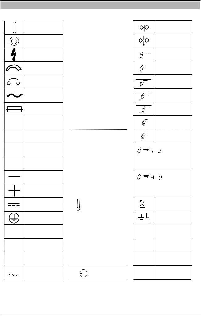
1.03 Symbol Chart
Note that only some of these symbols will appear on your model.
On
Off
Dangerous Voltage
Increase/Decrease
Circuit Breaker
AC Auxiliary Power
Fuse
Amperage
Voltage
Hertz (cycles/sec)
Frequency
Negative
Positive
Direct Current (DC)
Protective Earth (Ground)
Line
Line Connection
Auxiliary Power
115V 15A Receptacle Rating-
Auxiliary Power
|
|
|
|
|
Single Phase |
|
|
|
|
|
|
|
|
|
|
|
Three Phase |
|
|
|
|
|
|
|
|
|
|
|
Three Phase Static |
|
|
|
|
|
Frequency Converter- |
|
|
|
|
|
Transformer-Rectifier |
|
|
|
|
|
|
|
|
|
|
|
Remote |
|
|
|
|
|
|
|
X |
|
Duty Cycle |
||
|
|
|
|
|
|
% |
Percentage |
||||
|
|
|
|
|
|
|
|
|
|
|
Panel/Local |
|
|
|
|
|
|
|
|
|
|
|
Manual Metal |
|
|
|
|
|
Arc Welding (MMAW) |
|
|
|
|
|
Gas Metal Arc |
|
|
|
|
|
Welding (GMAW) |
|
|
|
|
|
|
|
|
|
|
|
Gas Tungsten Arc |
|
|
|
|
|
Welding (GTAW) |
|
|
|
|
|
|
|
|
|
|
|
Air Carbon Arc |
|
|
|
|
|
Cutting (CAC-A) |
|
|
|
|
|
|
|
|
|
|
|
Constant Current |
|
|
|
|
|
|
|
|
|
|
|
Constant Voltage |
|
|
|
|
|
Or Constant Potential |
|
|
|
|
|
|
|
|
|
|
|
High Temperature |
|
|
|
|
|
|
|
|
|
|
|
|
|
|
|
|
|
|
|
|
|
|
|
Fault Indication |
|
|
|
|
|
|
|
|
|
|
|
Arc Force |
|
|
|
|
|
|
|
|
|
|
|
Touch Start (GTAW) |
|
|
|
|
|
|
|
|
|
|
|
Variable Inductance |
|
|
|
|
|
|
|
|
|
|
V |
Voltage Input |
|
|
|
|
||
|
|
|
|
|
|
|
|
|
|
|
|
Wire Feed Function
Wire Feed Towards
Workpiece With
Output Voltage Off.
Welding Torch
|
|
|
Purging Of Gas |
|
|
|
Continuous Weld |
|
|
|
Mode |
|
|
|
Spot Weld Mode |
|
|
t |
Spot Time |
|
|
|
|
t1 |
|
|
Preflow Time |
|
t2 |
|
Postflow Time |
|
|
|
|
|
|
|
2 Step Trigger |
|
|
|
Operation |
Press to initiate wirefeed and welding, release to stop.
4 Step Trigger
Operation
Press and hold for preflow, release to start arc. Press to stop arc, and hold for preflow.
t |
Burnback Time |
Disturbance In
Ground System
IPM Inches Per Minute
MPM Metres Per Minute
Art # A-10344_AB
Figure 1-1 Symbol Chart
GENERAL INFORMATION |
1-6 |
Manual 0-5231 |

TRANSMIG VAF4
1.04 Declaration of Conformity
Manufacturer: |
CIGWELD |
Address: |
71 Gower St, Preston |
|
Victoria 3072 |
|
Australia |
Description of equipment: CIGWELD Transmig VAF4 wire feeder and associated accessories.
Serial numbers are unique with each individual piece of equipment and details description, parts used to manufacture a unit and date of manufacture.
The equipment conforms to all applicable aspects and regulations of the ‘Low Voltage Directive’ (Directive 73/23/ EU, as recently changed in Directive 93/68/EU and to the National legislation for the enforcement of the Directive.
National Standard and Technical Specifications
The product is designed and manufactured to a number of standards and technical requirements among them are:
•IEC 60974-10 applicable to Industrial Equipment - generic emissions and regulations.
•AS 1674 Safety in welding and allied processes.
•IEC 60974-5 Arc welding equipment, Wirefeeders.
•(IEC) AS 60974.1 Arc welding equipment, Welding power sources.
Extensive product design verification is conducted at the manufacturing facility as part of the routine design and manufacturing process, to ensure the product is safe and performs as specified. Rigorous testing is incorporated into the manufacturing process to ensure the manufactured product meets or exceeds all design specifications.
CIGWELD has been manufacturing and merchandising an extensive equipment range with superior performance, ultra safe operation and world class quality for more than 30 years and will continue to achieve excellence.
Manual 0-5231 |
1-7 |
GENERAL INFORMATION |

TRANSMIG VAF4
This page intentionally blank
GENERAL INFORMATION |
1-8 |
Manual 0-5231 |

TRANSMIG VAF4
SECTION 2: INTRODUCTION
2.01 How to Use This Manual
To ensure safe operation, read the entire manual, including the chapter on safety instructions and warnings. Throughout this manual, the word WARNING, CAUTION and NOTE may appear. Pay particular attention to the information provided under these headings. These special annotations are easily recognized as follows:
!WARNING
Gives information regarding possible personal injury. Warnings will be enclosed in a box such as this.
 CAUTION
Refers to possible equipment damage. Cautions will be shown in bold type.
NOTE
Offers helpful information concerning certain operating procedures. Notes will be shown in italics
Additional copies of this manual may be purchased by contacting Cigweld at the address and phone number for your location listed in the inside back cover of this manual. Include the Owner’s Manual number and equipment identification numbers.
2.02 Equipment Identification
The unit’s identification number (specification or part number), model, and serial number usually appear on a nameplate attached to the machine. Equipment which does not have a nameplate attached to the machine is identified only by the specification or part number printed on the shipping container. Record these numbers for future reference.
2.03 Receipt of Equipment
When you receive the equipment, check it against the invoice to make sure it is complete and inspect the equipment for possible damage due to shipping. If there is any damage, notify the carrier immediately to file a claim. Furnish complete information concerning damage claims or shipping errors to the location in your area listed in the inside back cover of this manual.
Include all equipment identification numbers as described above along with a full description of the parts in error.
Move the equipment to the installation site before un-crating the unit. Use care to avoid damaging the equipment when using bars, hammers, etc., to un-crate the unit.
Manual 0-5231 |
2-1 |
INTRODUCTION |
TRANSMIG VAF4
2.04 Description
The Transmig VAF4 offers both load and line voltage compensation helping to maintain a constant wire feed speed, even with changes in the input voltage and/or load.
The Transmig VAF4’s sheet metal box totally encloses the solid state control circuitry. A hinged, latched feedhead cover allows quick and easy access to the feedhead featuring quick change feed rolls, and tool-less knobs and clamps for changeover of guides and guns.
The Transmig VAF4 comes with an abundance of standard features including:
•an on/off rocker switch
•2 circuit breakers for total system protection
•a wire feed speed control
•a power source voltage control
•an inch switch
•a gas purge switch
•a 2T/ 4T/ Spot selector switch
•PC board adjustments for enhanced run in control
•a solid state electronic brake for dynamic braking
•two quick change, gear-driven feed rolls
•a gas valve solenoid
•an isolated gun trigger for operator safety
•a variety of add-on options to configure the unit for any wire-welding situation.
The Transmig VAF4 has been designed to comply with CSA NRTL/C, NEMA EW 3, and IEC 60974-1 standards.
The instructions in the next section detail how to correctly and safely set up the machine and give guidelines on gaining the best efficiency and quality from the Power Source. Please read these instructions thoroughly before using the unit.
2.05 User Responsibility
This equipment will perform as per the information contained herein when installed, operated, maintained and repaired in accordance with the instructions provided. This equipment must be checked periodically. Defective equipment (including welding leads) should not be used. Parts that are broken, missing, plainly worn, distorted or contaminated, should be replaced immediately. Should such repairs or replacements become necessary, it is recommended that such repairs be carried out by appropriately qualified persons approved by CIGWELD. Advice in this regard can be obtained by contacting an Accredited CIGWELD Distributor.
This equipment or any of its parts should not be altered from standard specification without prior written approval of CIGWELD. The user of this equipment shall have the sole responsibility for any malfunction which results from improper use or unauthorized modification from standard specification, faulty maintenance, damage or improper repair by anyone other than appropriately qualified persons approved by CIGWELD.
2.06 Transportation Methods
! |
WARNING |
ELECTRIC SHOCK can kill. DO NOT TOUCH live electrical parts. Disconnect wire feeder from Power Source before moving the wire feeder.
!WARNING
FALLING EQUIPMENT can cause serious personal injury and equipment damage.
Lift unit with integrated handle at the top of the unit. Use handcart or similar device of adequate capacity.
If using a fork lift vehicle, place and secure unit on a proper skid before transporting.
2.07 Packaged Items
Transmig VAF4 Wirefeeder (Part No.: W3000700)
•Transmig VAF4 Wirefeeder
•Operating Manual
•Drive Roll 0.9-1.2mm, V- groove fitted
•Handle Assembly
INTRODUCTION |
2-2 |
Manual 0-5231 |

|
|
|
|
TRANSMIG VAF4 |
||
|
|
|
|
|
|
|
|
|
|
|
|
|
|
2.08 Specifications |
|
|
|
|
|
|
|
|
|
|
|
|
|
|
Description |
|
Transmig VAF4 Wirefeeder |
|
||
|
Wirefeeder Part Number |
|
|
W3000700 |
|
|
|
Wirefeeder Dimensions |
H 345mm x W 275mm x D 610mm |
|
|||
|
Wirefeeder Mass |
|
|
19kg |
|
|
|
Input Voltage |
|
42VAC or 115VAC, 350VA |
|
||
|
Input Voltage Tolerance |
|
±15% |
|
|
|
|
Input Frequency |
|
|
50/60 Hz |
|
|
|
Gas Solenoid Voltage |
|
|
24vdc |
|
|
|
Maximum Gas Pressure |
|
|
0.7 Mpa (7 bar) |
|
|
|
MIG Welding Output, 40°C, 10 |
|
|
450A at 60% |
|
|
|
min |
|
|
350A at 100% |
|
|
|
Minimum Wire Feed Speed |
1.2 - 1.5 MPM (47 - 59 IPM) |
|
|
||
|
Maximum Wire Feed Speed |
22.1 - 22.5 MPM (870 - 886 IPM) |
|
|
||
|
Operating Temperature Range |
|
|
0°C - 40°C |
|
|
|
Interconnection Plug |
|
|
19pin |
|
|
|
|
Solid |
|
0.8mm (0.030”) to 1.6mm (1/16”) |
|
|
|
Wire Sizes |
Aluminium |
|
0.9mm (0.035”) to 1.6mm (1/16”) |
|
|
|
|
Flux Cored |
|
0.8mm (0.030”) to 2.0mm (5/64”) |
|
|
|
Maximum Wire Spool Weight |
|
|
60 lb./ 27kg |
|
|
|
|
|
|
|
|
|
Table 2-1 Transmig VAF4 Specification
NOTE
Due to variations that can occur in manufactured products, claimed performance, voltages, ratings, all capacities, measurements, dimensions and weights quoted are approximate only. Achievable capacities and ratings in use and operation will depend upon correct installation, use, applications, maintenance and service.
In the interest of continuous improvement, CIGWELD Pty. Ltd. reserves the right to change the specifications or design of any of its products without prior notice.
2.09 Optional Accessories
Feed Rolls
Wire Size |
Wire Type |
|
Part Number |
0.6mm/ 0.8mm |
Hard |
|
7977729 |
0.9mm/ 1.2mm* |
Hard |
|
7977703 |
1.2mm/ 1.6mm |
Hard |
|
7977346 |
0.8mm/ 0.9mm |
Soft |
|
7977733 |
|
|
|
|
1.0mm/ 1.2mm |
Soft |
|
7977730 |
|
|
|
|
1.2mm/ 1.6mm |
Soft |
|
7977348 |
0.8mm/ 0.9mm |
Cored |
|
7977734 |
1.2mm/ 1.6mm |
Cored |
|
7977347 |
1.6mm/ 2.0mm |
Cored |
|
7977372 |
Table 2-2 Feed Rolls |
|
||
note
Two feed rolls are required for each wire size.
note
* indicates fitted as standard.
Manual 0-5231 |
2-3 |
INTRODUCTION |

TRANSMIG VAF4
Other Accessories
Accessories |
Part Number |
Description |
|
TWECO No 4 MIG TORCH |
OTWX412/3545 |
Euro connection type, length is 3.6 metres, 400 |
|
3.6M EURO |
Amps @ 60%, contact tip OTW14/45 (1.2mm) |
||
|
|||
|
|
|
|
TWECO No 4 MIG TORCH |
OTWX415/3545 |
Euro connection type, length is 4.5 metres, 400 |
|
4.5M EURO |
Amps @ 60%, contact tip OTW14/45 (1.2mm) |
||
|
|||
|
|
|
|
TWECO SUPRA XT MIG |
SE400X4M16 |
Euro connection type, length is 4.0 metres, 450 |
|
TORCH 4.0M EURO |
Amps @ 60%, contact tip OTW15H/116 (1.6mm) |
||
|
|||
|
|
|
|
TWECO No 4 MIG TORCH |
717201 |
Tweco connection type, length is 3.6 metres, 400 |
|
3.6M Tweco 4 |
Amps @ 60%, contact tip OTW14/45 (1.2mm) |
||
|
|||
|
|
|
|
TWECO No 4 MIG TORCH |
717335 |
Tweco 4 connection type, length is 4.5 metres, 400 |
|
4.5M Tweco 4 |
Amps @ 60%, contact tip OTW14/45 (1.2mm) |
||
|
|||
|
|
|
|
TWECO SUPRA XT MIG |
SE4004M16 |
Tweco connection type, length is 4.0 metres, 450 |
|
TORCH 4.0M Tweco 4 |
Amps @ 60%, contact tip OTW15H/116 (1.6mm) |
||
|
|||
|
|
|
|
Interconnect Assy,19P- |
W4015900 |
19 pin to 19 pin, 2 metres in length, suitable for |
|
19P,2M |
Transmig 350i, 450i & 550i |
||
|
|||
|
|
|
|
Interconnect Assy,19P- |
W4015901 |
19 pin to 19 pin, 8 metres in length, suitable for |
|
19P,8M |
Transmig 350i, 450i & 550i |
||
|
|||
|
|
|
|
Interconnect Assy,19P- |
W4015902 |
19 pin to 19 pin, 15 metres in length,suitable for |
|
19P,15M |
Transmig 350i, 450i & 550i |
||
|
|||
|
|
|
|
Interconnect Assy,19P- |
W4016000 |
19 pin to 14 pin, 8 metres in length,suitable for |
|
14P,8M |
Transmig 400i, MPM8/255H, MPM8/270K |
||
|
|||
|
|
|
|
Adaptor Cable,19P-14P, |
W4016001 |
19 pin to 14 pin, 0.3 metres in length, required for |
|
0.3M |
MPM12/400K & MPM20/500P |
||
|
|||
|
|
|
|
|
|
Suitable for spools up to 300mm diameter. |
|
Spool Cover Assembly |
W4016300 |
Contains plastic spool cover and all necessary |
|
|
|
mounting hardware |
|
|
|
|
|
TWECO No 4 Adaptor |
|
Tweco No 4 connection, designed for Supra XT |
|
W4016400 |
MIG torch SE4004M16, Tweco No 4 MIG torch |
||
Assembly |
|||
|
717201 & 717335. Rated at 450A @ 60% |
||
|
|
||
|
|
|
|
Lifting Eye Kit |
W4016700 |
Electrically insulated. |
|
|
|
|
|
Heavy Duty 4 Wheel |
W4000001 |
Heavy duty, large castor wheel trolley for moving |
|
Trolley |
the Wirefeeder around the work area. |
||
|
|||
|
|
|
|
|
|
Specifically designed for MIG welding applications. |
|
Mig Pliers |
WSPLIER |
Manufactured from drop forged carbon steel. |
|
Spring loaded handle. Excellent for trimming MIG |
|||
|
|
||
|
|
wire or holding tips and nozzles. |
|
|
|
|
|
|
|
Measures leg length, root gap, plate |
|
Naka Measurement Gauge |
646265 |
thickness,convexity, wire and rod diameter and |
|
|
|
height of welds. |
|
|
|
|
|
Nozzle Dip |
702389 |
Supplied in 450g tin. Helps to prevent the adhesion |
|
of spatter to tips and nozzles. |
|||
|
|
||
|
Table 2-3 Options and Accessories |
||
INTRODUCTION |
2-4 |
Manual 0-5231 |
TRANSMIG VAF4
SECTION 3: INSTALLATION, Operation AND SETUP
3.01 Environment |
3.03 Ventilation |
These units are designed for use in environments with increased hazard of electric shock as outlined in IEC 60974.5.
A. Examples of environments with increased hazard of electric shock are:
1.In locations in which freedom of movement is restricted, so that the operator is forced to perform the work in a cramped (kneeling, sitting or lying) position with physical contact with conductive parts.
2.In locations which are fully or partially limited by conductive elements, and in which there is a high risk of unavoidable or accidental contact by the operator.
3.In wet or damp hot locations where humidity or perspiration considerably reduces the skin resistance of the human body and the insulation properties of accessories.
B. Environments with increased hazard of electric shock do not include places where electrically conductive parts in the near vicinity of the operator, which can cause increased hazard, have been insulated.
3.02 Location
Be sure to locate the wirefeeder according to the following guidelines:
A.In areas, free from moisture and dust.
B.Ambient temperature between 0° C to 40° C.
C.In areas, free from oil, steam and corrosive gases.
D.In areas, not subjected to abnormal vibration or shock.
E.In areas, not exposed to direct sunlight or rain.
F.The enclosure design of this Wire Feeder meets the requirements of IP23S as outlined in AS 60529. This provides adequate protection against solid objects (greater than 12mm), and direct protection from vertical drops. Under no circumstances should the unit be operated or connected in a micro environment that will exceed the stated conditions. For further information please refer to AS 60529.
G.Precautions must be taken against the Wire Feeder toppling over. The Wire Feeder must be located on a suitable horizontal surface in the upright position when in use.
!
WARNING
Since the inhalation of welding fumes can be harmful, ensure that the welding area is effectively ventilated.
3.04Mains Supply Voltage Requirements
CAUTION
This wirefeeder cannot be connected directly to the mains supply. It must be connected to a suitable wirefeeder control socket on a power source.
3.05 Electromagnetic Compatibility
! |
WARNING |
Extra precautions for Electromagnetic Compatibility may be required when this Welding Power Source is used in a domestic situation.
A. Installation and Use - Users Responsibility
The user is responsible for installing and using the welding equipment according to the manufacturer’s instructions. If electromagnetic disturbances are detected then it shall be the responsibility of the user of the welding equipment to resolve the situation with the technical assistance of the manufacturer. In some cases this remedial action may be as simple as earthing the welding circuit, see NOTE below. In other cases it could involve constructing an electromagnetic screen enclosing the Welding Power Source and the work, complete with associated input filters. In all cases, electromagnetic disturbances shall be reduced to the point where they are no longer Trouble-some.
NOTE
The welding circuit may or may not be earthed for safety reasons. Changing the earthing arrangements should only be authorised by a person who is competent to assess whether the changes will increase the risk of injury, e.g. by allowing parallel welding current return paths which may damage the earth circuits of other equipment. Further guidance is given in IEC 60974-13 Arc Welding Equipment - Installation and use (under preparation).
Manual 0-5231 |
3-1 |
INSTALLATION, OPERATION AND SETUP |

TRANSMIG VAF4
B. Assessment of Area
Before installing welding equipment, the user shall make an assessment of potential electromagnetic problems in the surrounding area. The following shall be taken into account.
1.Other supply cables, control cables, signalling and telephone cables; above, below and adjacent to the welding equipment.
2.Radio and television transmitters and receivers.
3.Computer and other control equipment.
4.Safety critical equipment, e.g. guarding of industrial equipment.
5.The health of people around, e.g. the use of pacemakers and hearing aids.
6.Equipment used for calibration and measurement.
7.The time of day that welding or other activities are to be carried out.
8.The immunity of other equipment in the environment: the user shall ensure that other equipment being used in the environment is compatible: this may require additional protection measures.
The size of the surrounding area to be considered will depend on the structure of the building and other activities that are taking place. The surrounding area may extend beyond the boundaries of the premises.
C. Methods of Reducing Electromagnetic Emissions
1.Mains Supply
Welding equipment should be connected to the mains supply according to the manufacturer’s recommendations. If interference occurs, it may be necessary to take additional precautions such as filtering of the mains supply. Consideration should be given to shielding the supply cable of permanently installed welding equipment in metallic conduit or equivalent. Shielding should be electrically continuous throughout its length. The shielding should be connected to the Welding Power Source so that good electrical contact is maintained between the conduit and the Welding Power Source enclosure.
2.Maintenance of Welding Equipment
The welding equipment should be routinely maintained according to the manufacturer’s recommendations. All access and service doors and covers should be closed and properly fastened when the welding equipment is in operation. The welding equipment should not be modified in any way except for those changes and adjustments covered in the manufacturer’s instructions.
3.Welding Cables
The welding cables should be kept as short as possible and should be positioned close together but never coiled and running at or close to the floor level.
4.Equipotential Bonding
Bonding of all metallic components in the welding installation and adjacent to it should be considered. However, metallic components bonded to the work piece will increase the risk that the operator could receive a shock by touching the metallic components and the electrode at the same time. The operator should be insulated from all such bonded metallic components.
5.Earthing/grounding of the Work Piece
Where the work piece is not bonded to earth for electrical safety, nor connected to earth because of its size and position, e.g. ship’s hull or building steelwork, a connection bonding the work piece to earth may reduce emissions in some, but not all instances. Care should be taken to prevent the earthing of the work piece increasing the risk of injury to users, or damage to other electrical equipment. Where necessary, the connection of the work piece to earth should be made by direct connection to the work piece, but in some countries where direct connection is not permitted, the bonding should be achieved by suitable capacitance, selected according to national regulations.
6.Screening and Shielding
Selective screening and shielding of other cables and equipment in the surrounding area may alleviate problems of interference. Screening the entire welding installation may be considered for special applications.
INSTALLATION, OPERATION AND SETUP |
3-2 |
Manual 0-5231 |
TRANSMIG VAF4
3.06 Front Panel Controls, Indicators and Features
6
14
8 |
3 |
4 |
5 |
1 |
2 |
9 |
|
|
|
|
|
|
10 |
|
|
|
|
|
|
11 |
|
|
|
|
|
|
12 |
|
|
|
|
|
|
13 |
|
|
|
|
|
|
7 |
|
|
|
|
|
|
15 |
Art # A-11255_AB
Figure 3-1 Front Panel View
 WARNING
DO NOT TOUCH the electrode wire while it is being fed through the system. The electrode wire will be at welding voltage potential.
1. POWER Indicator
The red power indicator will be illuminated when the Wirefeeder is turned ON and indicates the presence of power.
2. FAULT Indicator
The yellow fault indicator will be illuminated when any faults are detected. Should a fault condition occur refer to Subsections 3.30, 3.31, 4.05 or 4.08 for further information.
If the Fault indicator is flashing whilst welding refer to Subsection 3.31 as the motor overload protection is active.
3. AMPS Indicator
The red AMPS indicator will be illuminated when the Left Display displays the amperage.
4. IPM Indicator
The red IPM indicator will be illuminated when the Left Display displays WFS in Inches Per Minute (IPM).
5. MPM Indicator
The red MPM indicator will be illuminated when the Left Display displays WFS in Metres Per Minute (MPM).
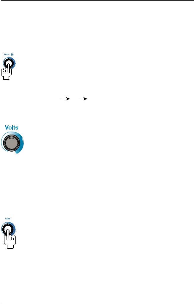
6. Left Knob
Amps / (Wirespeed)
Left Knob
The control knob adjusts Wire Feed Speed (WFS) (which in turn adjusts the output current by turning the amount of MIG wire delivered to the welding arc). The optimum WFS required is dependent on the type of welding application. The value may also be adjusted while a weld is in progress – if this occurs, the left display will briefly
Manual 0-5231 |
3-3 |
INSTALLATION, OPERATION AND SETUP |
TRANSMIG VAF4
plication. The value may also be adjusted while a weld is in progress – if this occurs, the left display will briefly switch to show the adjusted value as the knob is turned, and will automatically revert back to show the weld current measurements when the knob is not being turned. Turn the left knob either clockwise to increase WFS or counterclockwise to decrease WFS by increments of 0.1MPM. To increment in steps of 1 MPM whilst holding the left knob depressed turn it either clockwise to increase WFS or counterclockwise to decrease WFS.
The Left digital meter display option can be changed either via the Advanced Features Menu (refer to Subsection 3.08)
OR
By simply depressing the Left Amps control knob for 3 seconds whilst welding, then by releasing the knob and then holding it depressed for a further 3 seconds will increment to the next available display option that is shown on the left digital display. i.e. Amps WFS ---- (blank).
Press Left Knob (Amps) and Right Knob (Volts) for 1.2 seconds to enter or exit from the advanced programming mode. Please refer to Subsection 3.08 for Advanced Features Details.
7. Right Knob
Right Knob
The control knob adjusts the output voltage of the power source. The welding voltage is increased by turning the knob clockwise or decreased by turning the knob counter-clockwise. The value may also be adjusted while a weld is in progress – if this occurs, the right display will briefly switch to show the adjusted value as the knob is turned, and will automatically revert back to show the weld voltage measurements when the knob is not being turned. Turn the right knob either clockwise to increase voltage or counterclockwise to decrease voltage by increments of 0.1V. To increment in steps of 1V whilst holding the right knob depressed turn it either clockwise to increase WFS or counterclockwise to decrease WFS.
The Right digital meter display option can be changed either via the Advanced Features Menu (refer to Subsection 3.08)
OR
By simply depressing the Right Amps control knob for 3 seconds whilst welding, then by releasing the knob and then holding it depressed for a further 3 seconds will increment to the next available display option that is shown on the right digital display. i.e. VARC ---- (blank).
Press Left Knob (Amps) and Right Knob (Volts) for 1.2 seconds to enter or exit from the advanced programming mode. In advanced programming mode, turning the knob clockwise to increase and counter-clockwise to decrease the value on right display. Please refer to Subsection 3.08 for Advanced Features Details.
INSTALLATION, OPERATION AND SETUP |
3-4 |
Manual 0-5231 |

TRANSMIG VAF4
8. Left Digital Display
Left display is a 4- digit display.
In advanced programming mode, this display is used to display advanced features details or simply "----". Please refer to Subsection 3.08 for Advanced Features Details.
When welding, this digital meter will display WFS in Inches Per Minute (IPM) or Metres Per Minute (MPM) and actual welding amperage of the power source; it can also simply display "----" when the VAF4 is connected to a power source without a control signal on pin U of the 19 pin interconnection. The VAF4 uses this signal on pin U of the 19 pin interconnection to display welding amps, if this signal is not present from the power source, set the display to show "----". Press left knob and select the information on left display. At times of non-welding, the digital meter will display a pre-set (preview) WFS value. This value can be adjusted by turning the Left Knob (Control No. 6).
At the completion of welding, the digital meter will hold the last recorded value for a period of approximately 10 seconds. The meter will hold the value until: (1) any of the front panel controls are adjusted in which case the unit will revert to preview mode, (2) welding is recommenced, in which case actual welding amperage will be displayed, or (3) a period of 10 seconds elapses following the completion of welding in which case the unit will return to preview mode.
The display is also used for providing error messages to the user. Please refer to Subsection 4.05 for Error Codes and Remedies.
9. Right Digital Display
Right display is a 4- digit display.
This digital meter is used to display the pre-set (preview) Voltage in MIG mode and actual welding voltage of the power source or simply "----" when the VAF4 is connected to a power source without a control signal on pin C of the 19 pin interconnection. The VAF4 uses this signal on pin C of the 19 pin interconnection to display welding volts, if this signal is not present from the power source, set the display to show "----". Press right knob and select the information on right display. At times of non-welding, the digital meter will display a pre-set (preview) value of Voltage. This value can be adjusted by turning the Right Knob (Control No 7).
At the completion of welding, the digital meter will hold the last recorded voltage value for a period of approximately 10 seconds in all modes. The voltage meter will hold the value until: (1) any of the front panel controls are adjusted in which case the unit will revert to preview mode, (2) welding is recommenced, in which case actual welding voltage will be displayed, or (3) a period of 10 seconds elapses following the completion of welding in which case the unit will return to preview mode.
The display is also used for providing error messages to the user and showing other information. Please refer to Subsection 4.05 for Error Codes and Remedies.
10. 2T - 4TSPOT Trigger Mode Control Button
Press and release the button to change the selected operating mode of the trigger. The selected mode can be “2T”, “4T” or "Spot” operation. The red indicator next to the button will illuminate to identify which mode is selected. In the 4T mode once the weld has been started you can release the trigger and continue welding until the trigger is activated again or the welding arc is broken to stop the welding arc. Please refer to Subsection 3.25 - 3.28 for more details.
Manual 0-5231 |
3-5 |
INSTALLATION, OPERATION AND SETUP |
TRANSMIG VAF4
Note
In Advanced Features Mode Trigger Mode and SCH1-SCH2 can't be changed. In Spot Mode Stitch Mode is not available. Crater is only available in 4T Trigger Mode.
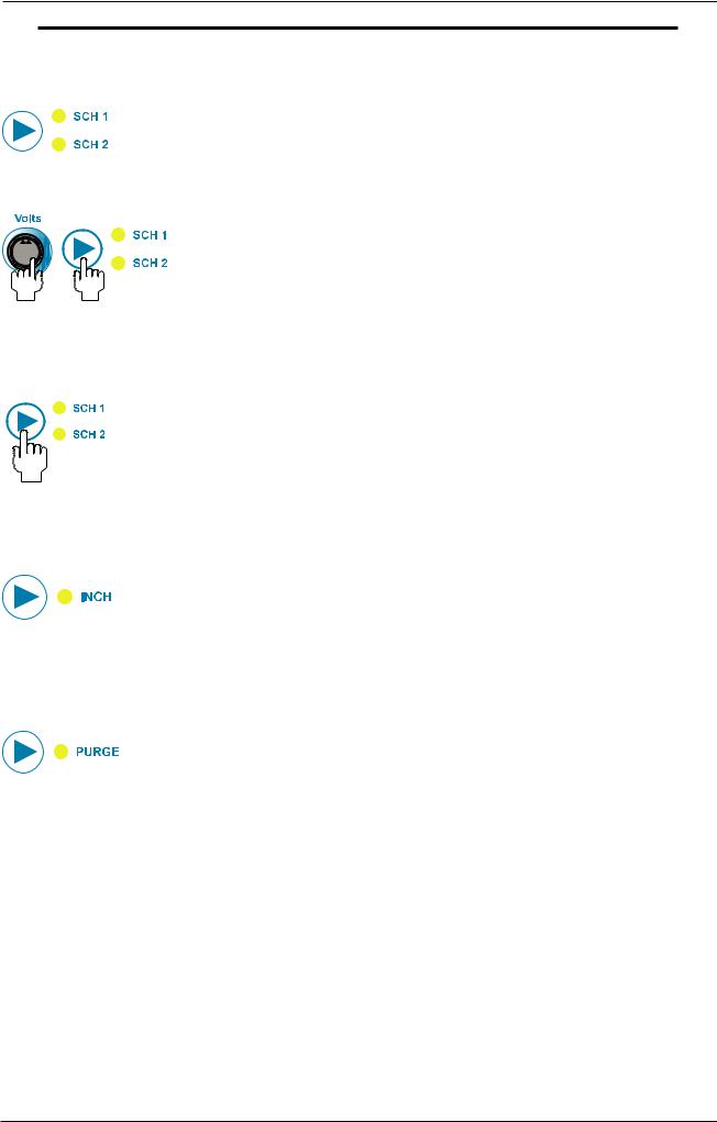
11. SCH 1-SCH 2 Button
This allows the user to save parameter settings in either Schedule 1 (SCH 1) or Schedule 2 (SCH 2) locations. Press the button to select either SCH 1 or SCH 2. The red indicator will illuminate to identify which schedule is selected.
Right Knob
Adjust the wire speed and weld volts, along with parameters such as burnback, pre flow, post flow etc, to the desired setting. Whilst holding the volts knob depressed at the same time press the SCH 1-SCH 2 button for 1.8 seconds to save the schedule. The SCH 1 or SCH 2 LED will flash 3 times to indicate the save has been successful. Note that all adjustable parameters are saved with each schedule.
If the user wishes to load settings saved in either SCH 1 or SCH 2 locations, press and release the SCH 1-SCH 2 button to select either SCH 1 or SCH 2, the red indicator will illuminate to identify which Schedule is selected.
12. INCH Button
After turning the power ON, press this button and hold it to start cold feeding. Left display shows actual WFS and right display shows INCH. If the user wishes to adjust WFS, turn left knob and left display shows preset WFS. 1 second later, it shows actual WFS. Release the button when it feeds the wire to the torch.
13. PURGE Button
This button is used to initiate gas line purge function to fill the gas line with the shielding gas from the connected gas cylinder. Press and hold the button depressed to start gas purge function, at which time a countdown timer will show in left display indicating the number of seconds remaining. You can stop the gas purge any time during the 30 seconds by releasing the button.
14. MIG Torch Adaptor
The MIG Torch adaptor is the connection point for the MIG welding Torch. Connect the MIG Torch by pushing the MIG Torch connector into the brass MIG Torch adaptor firmly and screwing the plastic MIG Torch nut clockwise to secure in position. To remove the MIG Torch simply reverse these directions.
INSTALLATION, OPERATION AND SETUP |
3-6 |
Manual 0-5231 |
TRANSMIG VAF4
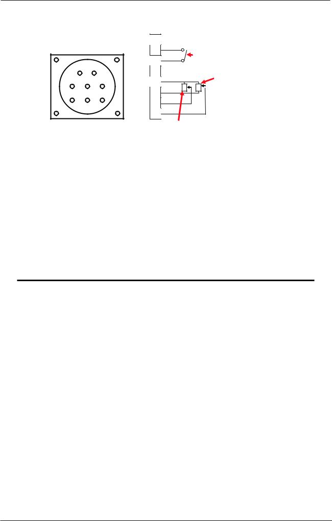
15. Remote Control Socket
The 8 pin Remote Control Socket is used to connect remote control devices to the welding power source. To make connections, align keyway, insert plug, and rotate threaded collar fully clockwise.
|
|
|
1 |
|
|
|
|
|
|
|
2 |
|
Trigger Switch |
||
|
|
|
3 |
|
|||
2 |
|
1 |
|
|
|
||
|
4 |
|
|
|
|||
|
|
|
|
|
Remote Volts in |
||
5 |
4 |
3 |
5 |
|
|
||
W |
V |
GMAW Mode |
|||||
8 |
7 |
6 |
6 |
||||
|
|
|
|||||
|
|
|
7 |
|
|
|
|
|
|
|
8 |
|
|
|
|
|
Remote Wirespeed in GMAW mode |
|
Figure 3-2 Remote Control Socket |
|
|
Socket Pin |
Function |
|
|
1 |
Not connected |
|
|
2 |
Trigger Switch Input |
|
|
3 |
Trigger Switch Input |
|
|
4 |
Not connected |
|
|
5 |
5k ohm (maximum) connection to 5k ohm remote control potentiometer. |
|
|
6 |
Zero ohm (minimum) connection to 5k ohm remote control potentiometer. |
|
|
7 |
Wiper arm connection to 5k ohm remote control Wirespeed MIG mode potentiometer. |
|
|
8 |
Wiper arm connection to 5k ohm remote control Volts MIG mode potentiometer. |
|
|
Table 3-1 Pin Function in Remote Control Socket
NOTE
The remote/ local setting in Advanced Features Menu should be set to remote for the remote wire feeder amperage/voltage controls to be operative.
Manual 0-5231 |
3-7 |
INSTALLATION, OPERATION AND SETUP |
TRANSMIG VAF4
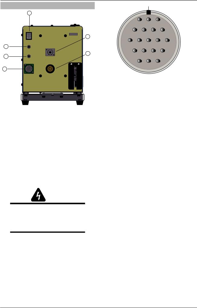
3.07 Rear Panel Controls and Features
16
17
20
19
21
18
Art# A-11256
Figure 3-3 Rear Panel View
16. ON/ OFF Switch
Press this switch to turn ON or turn OFF the Wirefeeder.
17. Gas Inlet
Gas inlet allows to connect the shield gas.
18. Control Cable Socket
The control cable connects to the power source at this 19-pin amphenol connector. It contains the signals required to allow the welding power source and the wire feeder to work together as a system.
WARNING
The protective earth ground (pin G) of the control cable is established ONLY when the power source is properly grounded. See the power source owner’s manual for proper grounding methods.
19. Welding Cable Connector
This connector allows to connect welding cable with Wirefeeder. Please make sure that it is secured firmly, or it will heat and generate arc.
20. 4A Circuit Breaker
This circuit breaker protects the wirefeeder from electrical faults on the 115VAC circuit. In the event of a fault occuring this circuit breaker will trip (pop out). A short cooling period must be allowed before an attempt is made to reset it by pressing it back in. Refer to Subsection 4.08 for further details.
Keyway
|
L |
M |
A |
|
|
K |
U |
N |
B |
J |
T |
V |
P |
C |
|
H |
S |
R |
D |
|
G |
F |
E |
|
|
Figure 3-4 Pin Identification |
|
|
|
|
Control Cable |
Function |
|
Pin |
|
|
|
|
|
|
|
|
A |
|
Contactor + (Shorted to B |
|
to turn ON Power Source) |
|
|
|
|
B |
|
Contactor- (Shorted to A to |
|
turn ON Power Source) |
|
|
|
|
|
|
Voltage Feedback ( 1 |
C |
|
Volt is 10 Arc Volts) |
|
|
|
|
|
|
D |
|
Not Used |
E |
|
115 VAC Hot |
F |
|
42VAC and 115VAC Neutral |
G |
|
Protective Earth Ground |
H |
|
Remote Control Maximum |
J |
|
Remote Control Signal |
K |
|
Not Used |
L |
|
Power Source Common |
M |
|
Arc Established (= +15 VDC) |
N |
|
Power Source Select Line |
P |
|
Not Used |
R |
|
Not Used |
S |
|
42VAC Live Wire |
T |
|
Not Used |
U |
|
Current Feedback (1 Volt |
|
is 100 Arc Amps) |
|
|
|
|
V |
|
Not Used |
Table 3-2 Control Cable Pin Functions
21. 8A Circuit Breaker
This circuit breaker protects the wirefeeder from electrical faults on the 42VAC circuit. In the event of a fault occuring this circuit breaker will trip (pop out). A short cooling period must be allowed before an attempt is made to reset it by pressing it back in. Refer to Subsection 4.08 for further details.
INSTALLATION, OPERATION AND SETUP |
3-8 |
Manual 0-5231 |

TRANSMIG VAF4
3.08 Advanced Features Mode
Enter Advanced Features Mode by pressing both the left knob and right knob at the same time for more than 1.2 seconds.
note
In Advanced Features Mode the Trigger Mode Control Button, SCH 1-SCH 2 button is inactive.
Exit Advanced Features Mode by pressing both the left knob and right knob at the same time for more than 1.2 seconds to Save the Settings and exit advanced features mode. Note if there has been no user input for 30 seconds, the VAF4 will save settings and automatically exit advanced programming mode.
Advanced Feature |
Left Display |
Right Display |
|
|
Feature Description |
Parameter / Selection |
|
Local / Remote |
|
|
|
This is used to select local panel |
|
|
|
control on the Wirefeeder, or remote |
|
|
|
control from the 8 pin remote |
|
|
|
control socket on the front of the |
|
|
|
Wirefeeder |
|
|
|
Default Local / Remote = Local |
|
Local / Remote |
|
|
If MIG Remote is selected but no remote control device is connected to the 8 pin |
||
|
control socket then the wirefeed speed will be 1.3MPM (minimum wirespeed) and |
||
|
the voltage will be 14V (minimum volts). |
||
Pre Flow |
|
|
|
This is used to provide gas to the |
|
|
|
weld zone prior to the wire striking |
|
|
|
an arc. |
|
0.0 – 5.0 seconds |
|
Default Pre Flow = 0.1 sec |
|
|
|
Run In |
|
|
|
(Creep wirefeed speed) |
|
|
|
This is used to change Wirespeed to |
|
|
|
a percentage of the value set by the |
|
30 – 150% of |
|
operator. It can improve arc starts |
|
Wirefeeder Speed |
|
by controlling the wire speed at the |
|
Setting |
|
instant the wire touches the base |
For example if you have 12m/min set speed and have 50% selected for Run-in |
||
metal. |
|||
Default Run In = 70% |
Speed, the speed of the wire will be 6m/min until the arc is established. Once the |
||
arc is established, the speed ramps up to the set speed at the rate set (12m/min) |
|||
|
|||
|
with Ramp Time described below. |
||
Manual 0-5231 |
3-9 |
INSTALLATION, OPERATION AND SETUP |
Loading...