


 Loading...
200  380V 400V 480V
PAK® 200i
PLASMA CUTTING SYSTEM
Operating
Manual
©
Revision: AA |
Issue Date: July 1, 2014 |
Manual No.: 0-5335 |
|
|
|
VictorThermalDynamics.com

WE APPRECIATE YOUR BUSINESS!
Congratulations on your new Victor Thermal Dynamics product. We are proud to have you as our customer and will strive to provide you with the best service and reliability in the industry. This product is backed by our extensive warranty and world-wide service network. To locate your nearest distributor or service agency call 1-800-426-1888, or visit us on the web at www.thermal-dynamics.com.
This Operating Manual has been designed to instruct you on the correct use and operation of your Victor Thermal Dynamics product. Your satisfaction with this product and its safe operation is our ultimate concern. Therefore please take the time to read the entire manual, especially the Safety Precautions. They will help you to avoid potential hazards that may exist when working with this product.
YOU ARE IN GOOD COMPANY!
The Brand of Choice for Contractors and Fabricators Worldwide.
Victor Thermal Dynamics is a Global Brand of manual and automation Plasma Cutting Products for Victor Technologies.
We distinguish ourselves from our competition through market-leading, dependable products that have stood the test of time. We pride ourselves on technical innovation, competitive prices, excellent delivery, superior customer service and technical support, together with excellence in sales and marketing expertise.
Above all, we are committed to developing technologically advanced products to achieve a safer working environment within the welding industry

! WARNINGS
Read and understand this entire Manual and your employer's safety practices before installing, operating, or servicing the equipment.
While the information contained in this Manual represents the Manufacturer's best judgement, the Manufacturer assumes no liability for its use.
Plasma Cutting Power Supply, Pak® 200i
Operating Manual No. 0-5335
Published by:
Victor Technologies, Inc. 82 Benning Street
West Lebanon, New Hampshire, USA 03784 (603) 298-5711
www.thermal-dynamics.com
© Copyright 2014 by
Victor Technologies International, Inc.
All rights reserved.
Reproduction of this work, in whole or in part, without written permission of the publisher is prohibited.
The publisher does not assume and hereby disclaims any liability to any party for any loss or damage caused by any error or omission in this Manual, whether such error results from negligence, accident, or any other cause.
Publication Date: July 1, 2014
Revision Date:
Record the following information for Warranty purposes:
Where Purchased: ___________________________________
Purchase Date:______________________________________
Power Supply Serial #:_______________________________
Torch Serial #:_______________________________________
This Page Intentionally Blank
TABLE OF CONTENTS
SECTION 1: |
|
|
GENERAL INFORMATION.............................................................................................. |
1-1 |
|
1.01 |
Notes, Cautions and Warnings.................................................................... |
1-1 |
1.02 |
Important Safety Precautions...................................................................... |
1-1 |
1.03 |
Publications................................................................................................. |
1-2 |
1.04 |
Note, Attention et Avertissement................................................................. |
1-3 |
1.05 |
Precautions De Securite Importantes.......................................................... |
1-3 |
1.06 |
Documents De Reference........................................................................... |
1-6 |
1.07 |
Declaration of Conformity............................................................................ |
1-7 |
1.08 |
Statement of Warranty................................................................................ |
1-8 |
SECTION 2: SPECIFICATIONS............................................................................................... |
2-1 |
|
2.01 |
General Description Of The System............................................................ |
2-1 |
2.02 |
Plasma Power Supply................................................................................. |
2-1 |
2.03 |
Plasma Cutting Torch.................................................................................. |
2-1 |
2.04 |
System Component Layout......................................................................... |
2-1 |
2.05 |
Power Supply Specifications & Electrical Requirements............................. |
2-2 |
2.06 |
Power Supply Dimensions.......................................................................... |
2-3 |
2.07 |
Power Supply Rear Panel Features............................................................ |
2-4 |
2.08 |
Gas Requirements...................................................................................... |
2-6 |
2.09 |
PCH/M 200 Torch Specifications................................................................ |
2-7 |
SECTION 3: INSTALLATION.................................................................................................... |
3-1 |
|
3.01 |
Installation Requirements............................................................................ |
3-1 |
3.02 |
Cables and Leads Identification.................................................................. |
3-2 |
3.03 |
Cables & Leads Identification...................................................................... |
3-2 |
3.04 |
Position the Power Supply.......................................................................... |
3-3 |
3.05 |
Primary Power Connections........................................................................ |
3-4 |
3.06 |
Connect Work Cable................................................................................... |
3-6 |
3.07 |
Connect Gas Supply Lines.......................................................................... |
3-7 |
3.08 |
Auxiliary Connections.................................................................................. |
3-8 |
3.09 |
Connect Torch Leads to the Arc Starter...................................................... |
3-8 |
3.10 |
Torch Parts Selection................................................................................ |
3-10 |
3:11 |
Fill Cooling System.................................................................................... |
3-12 |
SECTION 4: OPERATION........................................................................................................ |
4-1 |
|
4.01 |
Power Supply Indicators.............................................................................. |
4-1 |
4.02 |
Control Console Features........................................................................... |
4-2 |
4.03 |
Operating Set-up......................................................................................... |
4-3 |
4.04 |
System Operation........................................................................................ |
4-4 |
4.05 |
Gas Selection.............................................................................................. |
4-6 |
4.06 |
Power Supply Status Codes........................................................................ |
4-7 |
4.07 |
Cut Quality................................................................................................. |
4-13 |
4.08 |
Recommended Cutting Speeds................................................................ |
4-14 |
TABLE OF CONTENTS
SECTION 5: MAINTENANCE................................................................................................... |
5-1 |
|
5.01 |
General Maintenance.................................................................................. |
5-1 |
5.02 |
Coolant Filter Cleaning Procedure.............................................................. |
5-1 |
5.03 |
Coolant Replacement Procedure................................................................ |
5-2 |
5.04 |
Arc Starter Service...................................................................................... |
5-3 |
5.05 |
Arc Starter Spark Gap Adjustment.............................................................. |
5-4 |
SECTION 6: REPLACEMENT ASSEMBLIES & PARTS......................................................... |
6-1 |
|
6.01 |
Replacement Power Supply........................................................................ |
6-1 |
6.02 |
Leads and Cables....................................................................................... |
6-2 |
6.03 |
Power Supply External Replacement Parts ............................................... |
6-3 |
6.04 |
Power Supply Replacement Parts - Lower Right Side................................ |
6-4 |
6.05 |
Power Supply Replacement Parts - Upper Right Side................................ |
6-5 |
6.06 |
Power Supply Replacement Parts - Lower Left Side ................................. |
6-6 |
6.07 |
Power Supply Replacement Parts - Upper Left Side.................................. |
6-7 |
6.08 |
Power Supply Replacement Parts - Rear Panel......................................... |
6-8 |
6.09 |
Power Supply Replacement Parts - Front................................................... |
6-9 |
6.10 |
Recommended Gas Supply Hose............................................................. |
6-10 |
SECTION 7: |
TORCH MAINTENANCE................................................................................... |
7-1 |
7.01 |
Introduction.................................................................................................. |
7-1 |
7.02 |
General Torch Maintenance........................................................................ |
7-1 |
7.03 |
Common Operating Faults.......................................................................... |
7-2 |
7.04 |
Inspection and Replacement Consumable Torch Parts.............................. |
7-3 |
7.05 |
Troubleshooting Guide................................................................................ |
7-5 |
7.06 |
Servicing Hand Torch Components............................................................ |
7-7 |
7.07 |
Servicing Machine Torch Components....................................................... |
7-9 |
7.08 |
Torch And Leads Troubleshooting............................................................ |
7-10 |
APPENDIX 1: CONTROL MODULE....................................................................................... |
A-1 |
|
Control PCB Connections........................................................................................ |
A-1 |
|
Remote Functions.................................................................................................... |
A-2 |
|
Remote Connections................................................................................................ |
A-3 |
|
APPENDIX 2: CCM CPU PCB LAYOUT................................................................................ |
A-4 |
|
APPENDIX 3: CCM I/O PCB LAYOUT................................................................................... |
A-6 |
|
APPENDIX 4: PILOT PCB LAYOUT....................................................................................... |
A-8 |
|
APPENDIX 5: RELAY AND INTERFACE PCB LAYOUT..................................................... |
A-10 |
|
APPENDIX 6: DISPLAY PCB LAYOUT................................................................................ |
A-12 |
|
APPENDIX 7: SYSTEM BIAS PCB LAYOUT....................................................................... |
A-14 |
|
APPENDIX 8: MAIN INVERTER BOTTOM PCB LAYOUT................................................... |
A-16 |
|
APPENDIX 9: MAIN INVERTER TOP PCB LAYOUT........................................................... |
A-18 |
|
TABLE OF CONTENTS
APPENDIX 10: CONTROL AND FAULT PCB LAYOUT |
....................................................... A-20 |
|
APPENDIX 11: CAP BIAS BOTTOM PCB LAYOUT............................................................ |
A-22 |
|
APPENDIX 12: CAP BIAS TOP PCB LAYOUT.................................................................... |
A-23 |
|
APPENDIX 13: SUPPRESSOR PCB LAYOUT.................................................................... |
A-24 |
|
APPENDIX 14: GAS BOX LAYOUT..................................................................................... |
A-25 |
|
APPENDIX 15: COOLING DIAGRAM................................................................................... |
A-26 |
|
APPENDIX 16: SYSTEM SCHEMATICS ............................................................................ |
A-28 |
|
System Schematic 380V - 415VAC - pg1.............................................................. |
A-28 |
|
System Schematic 380V - 415VAC - pg2.............................................................. |
A-30 |
|
System Schematic 400V |
CE - pg1......................................................................... |
A-32 |
System Schematic 400V |
CE - pg2......................................................................... |
A-34 |
System Schematic 480V |
- pg1............................................................................... |
A-36 |
System Schematic 480V |
- pg2............................................................................... |
A-38 |
APPENDIX 17: ADVANCED TROUBLESHOOTING............................................................ |
A-40 |
|
APPENDIX 18: PUBLICATION HISTORY............................................................................ |
A-78 |
|
INTERNATIONAL CONTACT INFORMATION....................................................... |
BACK COVER |
|
TABLE OF CONTENTS
This Page Intentionally Blank
SECTION 1:
GENERAL INFORMATION
1.01 Notes, Cautions and Warnings
Throughout this manual, notes, cautions, and warnings are used to highlight important information. These highlights are categorized as follows:
NOTE
An operation, procedure, or background information which requires additional emphasis or is helpful in efficient operation of the system.
CAUTION
A procedure which, if not properly followed, may cause damage to the equipment.
!WARNING
A procedure which, if not properly followed, may cause injury to the operator or others in the operating area.
1.02 Important Safety Precautions
WARNING
OPERATION AND MAINTENANCE OF PLASMA ARC EQUIPMENT CAN BE DANGEROUS AND HAZARDOUS TO YOUR HEALTH.
Plasma arc cutting produces intense electric and magnetic emissions that may interfere with the proper function of cardiac pacemakers, hearing aids, or other electronic health equipment. Persons who work near plasma arc cutting applications should consult their medical health professional and the manufacturer of the health equipment to determine whether a hazard exists.
To prevent possible injury, read, understand and follow all warnings, safety precautions and instructions before using the equipment. Call 1-603-298-5711 or your local distributor if you have any questions.
PAK 200i
 GASES AND FUMES
Gases and fumes produced during the plasma cutting process can be dangerous and hazardous to your health.
•Keep all fumes and gases from the breathing area. Keep your head out of the welding fume plume.
•Use an air-supplied respirator if ventilation is not adequate to remove all fumes and gases.
•The kinds of fumes and gases from the plasma arc depend on the kind of metal being used, coatings on the metal, and the different processes. You must beverycarefulwhencuttingorweldinganymetals which may contain one or more of the following:
Antimony |
Chromium |
Mercury |
Arsenic |
Cobalt |
Nickel |
Barium |
Copper |
Selenium |
Beryllium |
Lead |
Silver |
Cadmium |
Manganese |
Vanadium |
•Always read the Material Safety Data Sheets
(MSDS) that should be supplied with the material you are using. These MSDSs will give you the in- formation regarding the kind and amount of fumes and gases that may be dangerous to your health.
•For information onhow totest for fumes and gases in your workplace, refer to item 1 in Subsection 1.03, Publications in this manual.
•Usespecialequipment,suchaswaterordowndraft cutting tables, to capture fumes and gases.
•Do not use the plasma torch in an area where com- bustibleorexplosivegasesormaterialsarelocated.
•Phosgene,a toxicgas,is generatedfromthevapors of chlorinated solvents and cleansers. Remove all sources of these vapors.
•WARNING: This product contains chemicals, including lead, known to the State of California to
cause birth defects and other reproductive harm.
Wash hands after handling.
ELECTRIC SHOCK
Electric Shock can injure or kill. The plasma arc process uses and produces high voltage electrical energy. This electric energy can cause severe or fatal shock to the operator or others in the workplace.
•Never touch any parts that are electrically “live” or “hot.”
•Wear dry gloves and clothing. Insulate yourself from the work piece or other parts of the welding circuit.
•Repair or replace all worn or damaged parts.
Manual 0-5335 |
GENERAL INFORMATION |
1-1 |
PAK 200i
•Extra care must be taken when the workplace is moist or damp.
•Install and maintain equipment according to NEC code, refer to item 9 in Subsection 1.03, Publications.
•Disconnect power source before performing any service or repairs.
•Read and follow all the instructions in the Operat- ing Manual.
 FIRE AND EXPLOSION
Fire and explosion can be caused by hot slag, sparks, or the plasma arc.
•Besurethereisnocombustibleorflammablemate- rial in the workplace. Any material that cannot be removed must be protected.
•To protect your eyes, always wear a welding hel- met or shield. Also always wear safety glasses with side shields, goggles or other protective eye wear.
•Wear welding gloves and suitable clothing to protect your skin from the arc rays and sparks.
•Keep helmet and safety glasses in good condition.
Replace lenses when cracked, chipped or dirty.
•Protect others in the work area from the arc rays. Use protective booths, screens or shields.
•Use the shadeof lens as suggestedin the following per ANSI/ASC Z49.1:
|
Minimum Protective |
Suggested |
Arc Current |
Shade No. |
Shade No. |
Less Than 300* |
8 |
9 |
300 - 400* |
9 |
12 |
400 - 800* |
10 |
14 |
•Ventilate all flammable or explosive vapors from the workplace.
•Do not cut or weld on containers that may have held combustibles.
•Provide a fire watch when working in an area where fire hazards may exist.
•Hydrogen gas may be formed and trapped under
aluminum workpieces when they are cut underwater or while using a water table. DO NOT cut aluminum alloys underwater or on a water table unless the hydrogen gas can be eliminated or dissipated. Trapped hydrogen gas that is ignited will cause an explosion.
 NOISE
NOISE
Noise can cause permanent hearing loss. Plasma arc processes can cause noise levels to exceed safe limits. You must protect your ears from loud noise to prevent permanent loss of hearing.
•To protect your hearing from loud noise, wear pro- tective ear plugs and/or ear muffs. Protect others in the workplace.
•Noise levels should be measured to be sure the decibels (sound) do not exceed safe levels.
•For information on how to test for noise, see item
1 in Subsection 1.03, Publications, in this manual.
 PLASMA ARC RAYS
Plasma Arc Rays can injure your eyes and burn your skin. The plasma arc process produces very bright ultra violet and infra red light. These arc rays will damage your eyes and burn your skin if you are not properly protected.
* These values apply where the actual arc is clearly seen. Experience has shown that lighter filters may be arc is hidden by the workpiece.
! WARNING
WARNING: This product contains chemicals, including lead, known to the State of California to cause birth defects and other reproductive harm.
Wash hands after handling.
1.03 Publications
Refer to the following standards or their latest revisions for more information:
1.OSHA, SAFETYAND HEALTH STANDARDS, 29CFR 1910, obtainable from the Superintendent of Docu- ments, U.S. Government Printing Office, Washington, D.C. 20402
2.ANSI Standard Z49.1, SAFETY IN WELDING AND CUTTING, obtainable from the American Welding Society, 550 N.W. LeJeune Rd, Miami, FL 33126
3.NIOSH, SAFETY AND HEALTH IN ARC WELDING AND GAS WELDING AND CUTTING, obtainable from the Superintendent of Documents, U.S. Govern- ment Printing Office, Washington, D.C. 20402
4.ANSI Standard Z87.1, SAFE PRACTICES FOR OC- CUPATION AND EDUCATIONAL EYE AND FACE PROTECTION, obtainable from American National
Standards Institute, 1430 Broadway, New York, NY
10018
5.ANSI Standard Z41.1, STANDARD FOR MEN’S SAFE- TY-TOE FOOTWEAR, obtainable from the American National Standards Institute, 1430 Broadway, New
York, NY 10018
|
GENERAL INFORMATION |
Manual 0-5335 |
6.ANSIStandardZ49.2,FIRE PREVENTION IN THE USE OF CUTTING AND WELDING PROCESSES, obtain- able from American National Standards Institute, 1430
Broadway, New York, NY 10018
7.AWSStandardA6.0,WELDINGAND CUTTING CONTAINERS WHICH HAVE HELD COMBUSTIBLES, obtainable from American Welding Society, 550 N.W. LeJeune Rd, Miami, FL 33126
8.NFPAStandard 51, OXYGEN-FUELGAS SYSTEMS FOR
WELDING, CUTTINGANDALLIED PROCESSES, obtainable from the National Fire Protection Association,
Batterymarch Park, Quincy, MA 02269
9.NFPA Standard 70, NATIONAL ELECTRICAL CODE, obtainable from the National Fire Protection Associa- tion, Batterymarch Park, Quincy, MA 02269
10.NFPAStandard 51B, CUTTINGAND WELDING PRO- CESSES, obtainable from the National Fire Protection
Association, Batterymarch Park, Quincy, MA 02269
11.CGA Pamphlet P-1, SAFE HANDLING OF COMPRESSED GASES IN CYLINDERS, obtainable from the Compressed Gas Association, 1235 Jefferson Davis
Highway, Suite 501, Arlington, VA 22202
12.CSAStandard W117.2, CODE FOR SAFETY IN WELD- ING AND CUTTING, obtainable from the Canadian
Standards Association, Standards Sales, 178 Rexdale Boulevard, Rexdale, Ontario, Canada M9W 1R3
13.NWSA booklet, WELDING SAFETY BIBLIOGRAPHY obtainable from the National Welding Supply Associa- tion, 1900 Arch Street, Philadelphia, PA 19103
14.AmericanWeldingSocietyStandardAWSF4.1,RECOM- MENDED SAFE PRACTICES FOR THE PREPARA-
TION FOR WELDINGAND CUTTING OF CONTAIN- ERS AND PIPING THAT HAVE HELD HAZARDOUS SUBSTANCES, obtainable from the American Welding Society, 550 N.W. LeJeune Rd, Miami, FL 33126
15.ANSI Standard Z88.2, PRACTICE FOR RESPIRATORY
PROTECTION, obtainable from American National
Standards Institute, 1430 Broadway, New York, NY
10018
PAK 200i
1.04Note, Attention et Avertissement
Dans ce manuel, les mots “note,” “attention,” et “aver- tissement” sont utilisés pour mettre en relief des infor- mations à caractère important. Ces mises en relief sont classifiées comme suit :
NOTE
Toute opération, procédure ou renseignement général sur lequel il importe d’insister davantage ou qui contribue à l’efficacité de fonctionnement du système.
ATTENTION
Toute procédure pouvant résulter l’endommagement du matériel en cas de nonrespect de la procédure en question.
!AVERTISSEMENT
Toute procédure pouvant provoquer des blessures de l’opérateur ou des autres personnes se trouvant dans la zone de travail en cas de non-respect de la procédure en question.
1.05Precautions De Securite Importantes
AVERTISSEMENTS
L’OPÉRATION ET LA MAINTENANCE DU MATÉRIEL DE SOUDAGE À L’ARC AU JET DE PLASMA PEUVENT PRÉSENTER DES RISQUES ET DES DANGERS DE SANTÉ.
Coupant à l’arc au jet de plasma produit de l’énergie électrique haute tension et des émissions magnétique qui peuvent interférer la fonction propre d’un “pacemaker” cardiaque, les appareils auditif, ou autre matériel de santé electronique. Ceux qui travail près d’une application à l’arc au jet de plasma devrait consulter leur membre professionel de médication et le manufacturier de matériel de santé pour déterminer s’il existe des risques de santé.
Il faut communiquer aux opérateurs et au personnel TOUS les dangers possibles. Afin d’éviter les blessures possibles, lisez, comprenez et suivez tous les avertissements, toutes les précautions de sécurité et toutes les consignes avant d’utiliser le matériel. Composez le + 603-298-5711 ou votre distributeur local si vous avez des questions.
Manuel 0-5335 |
INFORMATIONS GÉNÉRALES |
1-3 |

PAK 200i
 FUMÉE et GAZ
La fumée et les gaz produits par le procédé de jet de plasma peuvent présenter des risques et des dangers de santé.
•Eloignez toute fumée et gaz de votre zone de respira- tion. Gardez votre tête hors de la plume de fumée provenant du chalumeau.
•Utilisez un appareil respiratoire à alimentation en air si l’aération fournie ne permet pas d’éliminer la fumée et les gaz.
•Les sortes de gaz et de fumée provenant de l’arc de plasma dépendent du genre de métal utilisé, des revêtements se trouvant sur le métal et des différents procédés. Vous devez prendre soin lorsque vous coupez ou soudez tout métal pouvant contenir un ou plusieurs des éléments suivants:
antimoine |
cadmium |
mercure |
argent |
chrome |
nickel |
arsenic |
cobalt |
plomb |
baryum |
cuivre |
sélénium |
béryllium |
manganèse |
vanadium |
•Liseztoujourslesfiches dedonnéessurlasécuritédes matières(sigleaméricain“MSDS”);celles-cidevraient être fournies avec le matériel que vous utilisez. Les
MSDS contiennent des renseignements quant à la quantité et la nature de la fumée et des gaz pouvant poser des dangers de santé.
•Pour des informations sur la manière de tester la fumée et les gaz de votre lieu de travail, consultez l’article 1 et les documents cités à la page 5.
•Utilisez un équipement spécial tel que des tables de coupe à débit d’eau ou à courant descendant pour capter la fumée et les gaz.
•N’utilisez pas le chalumeau au jet de plasma dans une zone où se trouvent des matières ou des gaz combustibles ou explosifs.
•Le phosgène, un gaz toxique, est généré par la fumée provenant des solvants et des produits de nettoyage chlorés. Eliminez toute source de telle fumée.
•AVERTISSEMENT : Ce produit contient des produits chimiques, notamment du plomb, reconnu par l'État de la Californie pour causer des malformations con-
génitales et d'autres dommages touchant le système reproductif. Se laver les mains après manipulation.
 CHOC ELECTRIQUE
Les chocs électriques peuvent blesser ou même tuer. Le procédé au jet de plasma requiert et produit de l’énergie électrique haute tension. Cette énergie électrique peut produire des chocs graves, voire mortels, pour l’opérateur et les autres personnes sur le lieu de travail.
•Netouchezjamaisunepièce“soustension”ou“vive”; portez des gants et des vêtements secs. Isolez-vous de la pièce de travail ou des autres parties du circuit de soudage.
•Réparez ou remplacez toute pièce usée ou endom- magée.
•Prenezdessoinsparticulierslorsquelazonedetravail est humide ou moite.
•Montez et maintenez le matériel conformément au CodeélectriquenationaldesEtats-Unis. (Voirlapage
5, article 9.)
•Débranchez l’alimentation électrique avant tout tra- vail d’entretien ou de réparation.
•Lisez et respectez toutes les consignes du Manuel de consignes.
 INCENDIE ET EXPLOSION
Les incendies et les explosions peuvent résulter des scories chaudes, des étincelles ou de l’arc de plasma. Le procédé à l’arc de plasma produit du métal, des étincelles, des scories chaudes pouvant mettre le feu aux matières combustibles ou provoquer l’explosion de fumées inflammables.
•Soyez certain qu’aucune matière combustible ou in- flammable nesetrouvesurlelieudetravail.Protégez toute telle matière qu’il est impossible de retirer de la zone de travail.
•Procurez une bonne aération de toutes les fumées inflammables ou explosives.
•Ne coupez pas et ne soudez pas les conteneurs ayant pu renfermer des matières combustibles.
•Prévoyez une veille d’incendie lors de tout travail dans une zone présentant des dangers d’incendie.
•Le gas hydrogène peut se former ou s’accumuler sous les pièces de travail en aluminium lorsqu’elles sont coupées sous l’eau ou sur une table d’eau. NE PAS couper les alliages en aluminium sous l’eau ou sur une table d’eau à moins que le gas hydrogène peut s’échapper ou se dissiper. Le gas hydrogène accumulé explosera si enflammé.
|
INFORMATIONS GÉNÉRALES |
Manuel 0-5335 |

PAK 200i
RAYONS D’ARC DE PLASMA |
AVERTISSEMENT |
|
Les rayons provenant de l’arc de plasma peuvent blesser vos yeux et brûler votre peau. Le procédé à l’arc de plasma produit une lumière infra-rouge et des rayons ultra-violets très forts. Ces rayons d’arc nuiront à vos yeux et brûleront votre peau si vous ne vous protégez pas correctement.
•Pour protéger vos yeux, portez toujours un casque ou un écran de soudeur. Portez toujours des lunettes de sécurité munies de parois latérales ou des lunettes de protection ou une autre sorte de protection oculaire.
•Portezdesgantsdesoudeuretunvêtementprotecteur approprié pour protéger votre peau contre les étince- lles et les rayons de l’arc.
•Maintenez votre casque et vos lunettes de protection en bon état. Remplacez toute lentille sale ou com- portant fissure ou rognure.
•Protégez les autres personnes se trouvant sur la zone de travail contre les rayons de l’arc en fournissant des cabines ou des écrans de protection.
•Utilisez la nuance de lentille qui est suggèrée dans le recommendation qui suivent ANSI/ASC Z49.1:
|
Nuance Minimum |
Nuance Suggerée |
|
Courant Arc |
Protective Numéro |
Numéro |
|
Moins de 300* |
8 |
9 |
|
300 - 400* |
9 |
12 |
|
400 - 800* |
10 |
14 |
|
* Ces valeurs s’appliquent ou l’arc actuel est observé clairement. L’experience a démontrer que les filtres moins foncés peuvent être utilisés quand l’arc est caché par moiceau de travail.
 BRUIT
BRUIT
Le bruit peut provoquer une perte permanente de l’ouïe. Les procédés de soudage à l’arc de plasma peuvent provoquer des niveaux sonores supérieurs aux limites normalement acceptables. Vous dú4ez vous protéger les oreilles contre les bruits forts afin d’éviter une perte permanente de l’ouïe.
•Pour protéger votre ouïe contre les bruits forts, portez des tampons protecteurs et/ou des protections au- riculaires. Protégez également les autres personnes se trouvant sur le lieu de travail.
•Il faut mesurer les niveaux sonores afin d’assurer que les décibels (le bruit) ne dépassent pas les niveaux sûrs.
•Pour des renseignements sur la manière de tester le bruit, consultez l’article 1, page 5.
AVERTISSEMENT : Ce produit contient des produits chimiques, notamment du plomb, reconnus par l'État de Californie comme pouvant causer des malformations congénitales et d'autres troubles de la reproduction. Se laver les mains après toute manipulation.
Manuel 0-5335 |
INFORMATIONS GÉNÉRALES |
1-5 |

PAK 200i
1.06 Documents De Reference
Consultez les normes suivantes ou les révisions les plus récentes ayant été faites à celles-ci pour de plus amples renseignements :
1.OSHA, NORMES DE SÉCURITÉ DU TRAVAIL ET DE PROTECTION DE LA SANTÉ, 29CFR 1910, disponible auprès du Superintendent of Documents, U.S. Government Printing Office, Washington, D.C. 20402
2.NormeANSI Z49.1, LASÉCURITÉ DES OPÉRATIONS DE COUPE ET DE SOUDAGE, disponible auprès de la Société Américaine de Soudage (American Welding Society), 550 N.W. LeJeune Rd., Miami, FL 33126
3.NIOSH, LASÉCURITÉ ET LASANTÉ LORS DES OPÉRATIONS DE COUPE ET DE SOUDAGEÀL’ARC ETAU GAZ, disponible auprès du Superintendent of Documents, U.S. Government Printing Office, Washington, D.C. 20402
4.NormeANSIZ87.1,PRATIQUESSURESPOURLAPROTECTIONDESYEUXETDUVISAGEAUTRAVAILETDANS LES ECOLES, disponible de l’InstitutAméricain des Normes Nationales (American National Standards Institute), 1430
Broadway, New York, NY 10018
5.NormeANSI Z41.1, NORMES POUR LES CHAUSSURES PROTECTRICES, disponible auprès de l’American National Standards Institute, 1430 Broadway, New York, NY 10018
6.NormeANSI Z49.2, PRÉVENTION DES INCENDIES LORS DE L’EMPLOI DE PROCÉDÉS DE COUPE ET DE SOUD- AGE, disponible auprès de l’American National Standards Institute, 1430 Broadway, New York, NY 10018
7.NormeA6.0del’AssociationAméricaineduSoudage(AWS),LESOUDAGEETLACOUPEDECONTENEURSAYANT RENFERMÉ DES PRODUITS COMBUSTIBLES, disponible auprès de laAmerican Welding Society, 550 N.W. LeJeune Rd., Miami, FL 33126
8.Norme 51 de l’Association Américaine pour la Protection contre les Incendies (NFPA), LES SYSTEMES ÀGAZ AVEC
ALIMENTATION EN OXYGENE POUR LE SOUDAGE, LACOUPE ET LES PROCÉDÉS ASSOCIÉS, disponible auprès de la National Fire Protection Association, Batterymarch Park, Quincy, MA 02269
9.Norme 70 de la NFPA, CODE ELECTRIQUE NATIONAL, disponible auprès de la National Fire Protection Associa- tion, Batterymarch Park, Quincy, MA 02269
10.Norme 51B de la NFPA, LES PROCÉDÉS DE COUPE ET DE SOUDAGE, disponible auprès de la National Fire Protec- tion Association, Batterymarch Park, Quincy, MA 02269
11.Brochure GCA P-1, LA MANIPULATION SANS RISQUE DES GAZ COMPRIMÉS EN CYLINDRES, disponible au- près de l’Association des Gaz Comprimés (Compressed Gas Association), 1235 Jefferson Davis Highway, Suite 501,
Arlington, VA 22202
12.Norme CSA W117.2, CODE DE SÉCURITÉ POUR LE SOUDAGE ET LA COUPE, disponible auprès de l’Association des Normes Canadiennes, Standards Sales, 178 Rexdale Boulevard, Rexdale, Ontario, Canada, M9W 1R3
13.Livret NWSA, BIBLIOGRAPHIE SUR LA SÉCURITÉ DU SOUDAGE, disponible auprès de l’Association Nationale de Fournitures de Soudage (National Welding Supply Association), 1900 Arch Street, Philadelphia, PA 19103
14.Norme AWSF4.1 de l’Association Américaine de Soudage, RECOMMANDATIONS DE PRATIQUES SURES POUR
LA PRÉPARATION À LA COUPE ET AU SOUDAGE DE CONTENEURS ET TUYAUX AYANT RENFERMÉ DES
PRODUITS DANGEREUX , disponible auprès de la American Welding Society, 550 N.W. LeJeune Rd., Miami, FL 33126
15.Norme ANSI Z88.2, PRATIQUES DE PROTECTION RESPIRATOIRE, disponible auprès de l’American National Standards Institute, 1430 Broadway, New York, NY 10018
|
INFORMATIONS GÉNÉRALES |
Manuel 0-5335 |
PAK 200i
1.07 Declaration of Conformity
Declaration of Conformity
We Victor Technologies International Inc.
of 16052 Swingley Ridge Road
Suite 300
Chesterfield, MO 63033 U.S.A.
in accordance with the following Directive(s):
2006/95/EC The Low Voltage Directive
2004/108/EC The Electromagnetic Compatibility Directive
hereby declare that:
Equipment: Plasma Cutting Power Supply
Model Name/Number: PAK 200i
Market Release Date: July 10th, 2014
is in conformity with the applicable requirements of the following harmonized standards:
Harmonized Standard of “EMC Directive”
EN 60974-10:2007 Arc Welding Equipment - Part 10: Electromagnetic compatibility (EMC) requirements
Harmonized Standard of “Low Voltage Directive”
EN 60974-1:2012 Arc Welding Equipment - Part 1: Welding power sources.
Classification: The equipment described in this document is Class A and intended for industrial use.
!WARNING
This Class A equipment is not intended for use in residential locations where the electrical power is provided by the public low-voltage supply system. There may be potential difficulties in ensuring electromagnetic compatibility in those locations, due to conducted as well as radiated disturbances.
Manufacturer’s Authorized Representative |
|
|
|
Steve Ward V.P. Europe and General Manager |
|
|
|
|
|
|
|
Address:Victor Technologies International Inc. |
|
Steve Ward |
|
Europa Building |
|
(Full Name) |
|
Chorley N Industrial Park |
|
V.P. Europe and General Manager |
|
Chorley, Lancashire, |
|
|
|
|
(Position) |
|
|
England PR6 7BX |
|
|
|
|
|
|
|
Date: July 10, 2014 |
|
|
|
Manual 0-5335 |
GENERAL INFORMATION |
1-7 |

PAK 200i
1.08 Statement of Warranty
LIMITED WARRANTY: Victor Thermal Dynamics® Corporation (hereinafter “Thermal”) warrants that its products will be free of defects in workmanship or material. Should any failure to conform to this warranty appear within the time period applicable to the Thermal products as stated below, Thermal shall, upon notification thereof and substantiation that the product has been stored, installed, operated, and maintained in accordance with Thermal’s specifications, instructions, recommendations and recognized standard industry practice, and not subject to misuse, repair, neglect, alteration, or accident, correct such defects by suitable repair or replacement, at Thermal’s sole option, of any components or parts of the product determined by Thermal to be defective.
THIS WARRANTYIS EXCLUSIVEAND IS IN LIEU OFANYWARRANTYOF MERCHANTABILITYOR FITNESS FORAPARTICULAR PURPOSE.
LIMITATION OF LIABILITY: Thermal shall not under any circumstances be liable for special or consequential damages, such as, but not limited to, damage or loss of purchased or replacement goods, or claims of customers of distributor (hereinafter “Purchaser”) for service interruption. The remedies of the Purchaser set forth herein are exclusive and the liability of Thermal with respect to any contract, or anything done in connection therewith such as the performance or breach thereof, or from the manufacture, sale, delivery, resale, or use of any goods covered by or furnished by Thermal whether arising out of contract, negligence, strict tort, or under any warranty, or otherwise, shall not, except as expressly provided herein, exceed the price of the goods upon which such liability is based.
THIS WARRANTY BECOMES INVALID IF REPLACEMENT PARTS OR ACCESSORIES ARE USED WHICH MAY IMPAIR THE SAFETY OR PERFORMANCE OF ANY THERMAL PRODUCT.
THIS WARRANTY IS INVALID IF THE PRODUCT IS SOLD BY NON-AUTHORIZED PERSONS.
The limited warranty periods for this product shall be: A maximum of three (3) years from date of sale to an authorized distributor and a maximum of two (2) years from date of sale by such distributor to the Purchaser, and with further limitations on such two (2) year period (see chart below).
|
|
Parts |
Labor |
PAK®200i Power Supplies and Components |
2 Years |
1 Year |
|
Torch And Leads |
|
|
|
PCH/M Torch (Excluding Consumable Parts) |
|
1 Year |
1 Year |
Repair/Replacement Parts |
|
90 Days |
90 Days |
Warranty repairs or replacement claims under this limited warranty must be submitted by an authorized Thermal Dynamics® repair facility within thirty (30) days of the repair. No transportation costs of any kind will be paid under this warranty. Transportation charges to send products to an authorized warranty repair facility shall be the responsibility of the customer. All returned goods shall be at the customer’s risk and expense. This warranty supersedes all previous Thermal warranties.
Effective October 23, 2012
|
GENERAL INFORMATION |
Manual 0-5335 |
PAK 200i
SECTION 2: SPECIFICATIONS
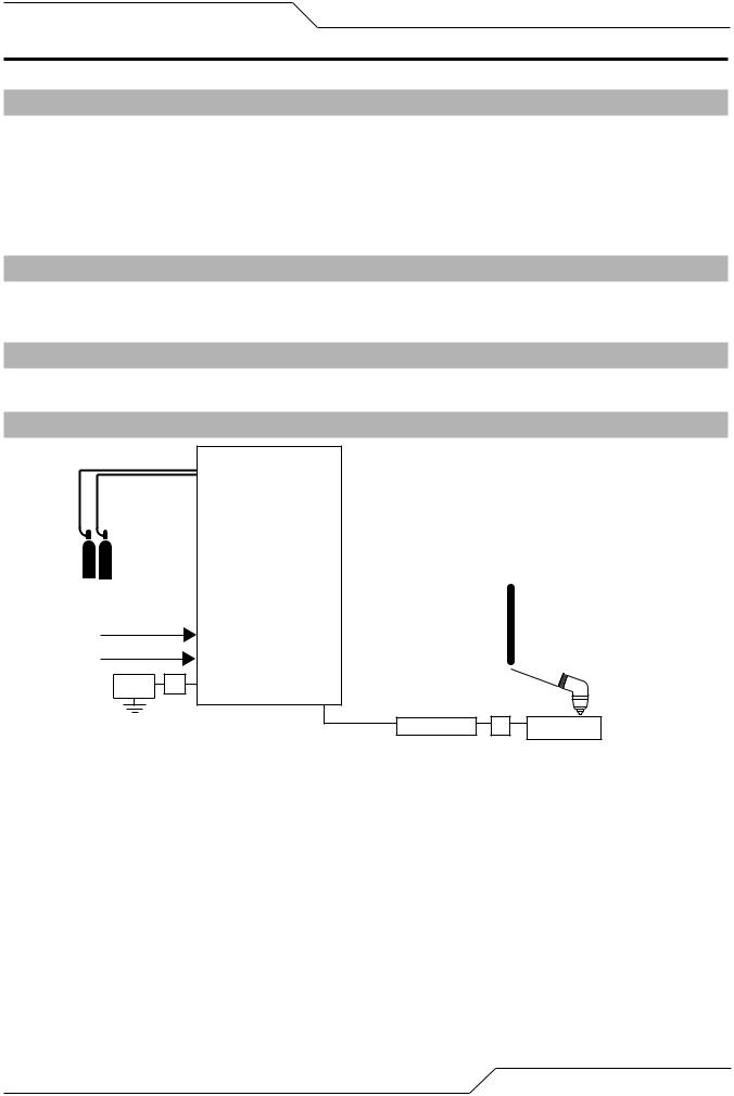
2.01 General Description Of The System
A typical PAK 200i plasma cutting system includes:
•One Power Supply
•General Purpose Plasma Cutting Torch with Connecting Leads
•Torch Spare Parts Kit
The components are connected at installation.
2.02 Plasma Power Supply
The power supply provides the necessary current for cutting operations, and monitors system performance. The power supply also cools and circulates the liquid coolant for the torch and leads.
2.03 Plasma Cutting Torch
The torch delivers the controlled current to the work through the main arc, causing the metal to be cut.
2.04 System Component Layout
PAK 200i
Power Supply
Primary power |
||
Ground |
F1 |
|
Cable |
||
|
||
|
|
|
|
|
|
|
|
|
|
|
|
|
|
|
|
|
|
G: Torch Lead Set, Shielded |
||
|
Torch |
|
||||
|
|
- Coolant Supply w/Negative |
||||
|
Control/ |
|
||||
|
|
- Coolant Return |
||||
|
Pendant |
|
||||
|
|
- Control Cable |
||||
|
|
|
|
|||
|
|
|
|
- Plasma Gas w/Pilot Return |
||
|
|
|
|
- Shield Gas |
||
|
|
|
|
|||
|
|
|
|
|
|
|
 Torch
Torch
Work Cable |
O |
Work |
Art # A-12371
Manual 0-5335 |
SPECIFICATIONS |
2-1 |
PAK 200i
2.05 Power Supply Specifications & Electrical Requirements
PAK 200i 380V Power Supply Specifications
Max OCV (U0) |
400 vdc |
Max Output Current |
200 Amps |
Output Voltage |
60 - 160 vdc |
Duty Cycle Rating |
100% @ 200A @ 200V (40 kW) |
Operating range |
14°F to 122°F (-10°C to + 50°C) |
Power Factor |
0.94 @ 200 ADC Output |
Cooling |
Forced Air (Class F) and Liquid Cooled |
|
|
PAK 200i 400V Power Supply Specifications |
|
Max OCV (U0) |
425 vdc |
Max Output Current |
200 Amps |
Output Voltage |
60 - 160 vdc |
Duty Cycle Rating |
100% @ 200A @ 200V (40 kW) |
Operating range |
14°F to 122°F (-10°C to + 50°C) |
Power Factor |
0.94 @ 200 ADC Output |
Cooling |
Forced Air (Class F) and Liquid Cooled |
|
|
PAK 200i 480V Power Supply Specifications |
|
Max OCV (U0) |
425 vdc |
Max Output Current |
200 Amps |
Output Voltage |
60 - 160 vdc |
Duty Cycle Rating |
100% @ 200A @ 160V (32 kW) |
Operating range |
14°F to 122°F (-10°C to + 50°C) |
Power Factor |
0.94 @ 200 ADC Output |
Cooling |
Forced Air (Class F) and Liquid Cooled |
PAK 200i Power Supply
|
Input |
|
|
Suggested Sizes (See Note) |
|||
Voltage |
Freq. |
Power |
Current |
Fuse |
Wire (AWG) |
Wire (mm2) |
|
(3-Ph) |
(3-Ph) |
(Amps) |
|||||
|
|
|
|
||||
|
|
|
|
|
|
|
|
(Volts) |
(Hz) |
(kVA) |
(Amps) |
3-Ph |
3-Ph |
3-Ph |
|
380 |
50/60 |
39 |
60 |
100 |
#6 |
16 |
|
400 |
50/60 |
39 |
57 |
100 |
#6 |
16 |
|
480 |
50/60 |
39 |
47 |
90-100 |
#8 |
10 |
|
* Suggested wire size based on United States NFPA 70 National Electrical Code 2011 edition published by the National Fire Prevention Association. Listings are from table 400.5(A)(2) for flexible cord of certain types rated for 75 deg C in ambient temperatures up to 30 deg C. Using wires of lower temperature rating or different insulation type may require larger wire size. Derate for higher ambient.
These are suggestions only. Always refer to your local and national codes that apply to your region for final determination of correct wire type and size.
CAUTION
Fuse and wire sizes are for reference only. The installation must conform to national and local codes for the type and method of wire being used.
|
SPECIFICATIONS |
Manual 0-5335 |
PAK 200i
2.06 Power Supply Dimensions
47.77 inch
1213 mm
35.97 inch
|
914 mm |
27.6 inch |
490 lb / 222 kg |
|
|
701 mm |
|
|
Art # A-11460_AB |
Manual 0-5335 |
SPECIFICATIONS |
2-3 |
PAK 200i
2.07 Power Supply Rear Panel Features
Customer |
Circuit Breakers |
Optional |
|
Ports |
|
To Torch
C.C.M. 
|
USER INPUT |
|
|
HEIGHT CONTROL |
|
J15 - CNC |
AIR / O2 |
N2 / H35 |
PLASMA |
PLASMA |
|
|
CB2 - 5A 120 VAC |
|
|
CB3 - 5A 24 VAC |
|
|
CB4 - 5A 120 VAC |
|
F1 - 8A SB 230 VAC |
F2 - 8A SB 230 VAC |
|
Fuses 
 Plasma Gas Port
 Shield Gas Port
 Torch Leads Port
Torch Leads
Ground Terminal
 Work Cable Port
Two Stage
Air Filter
Coolant Filter 
Input Power
Ground Terminal
on inside
Art # A-12372
Figure 2-3: 400V CE Rear Panel
|
SPECIFICATIONS |
Manual 0-5335 |
Customer
Optional
Ports
To Torch
C.C.M. 
Fuses 
Coolant Filter 
Circuit Breakers
|
USER INPUT |
|
|
HEIGHT CONTROL |
|
J15 - CNC |
AIR / O2 |
N2 / H35 |
PLASMA |
PLASMA |
|
|
CB2 - 5A 120 VAC |
|
|
CB3 - 5A 24 VAC |
|
|
CB4 - 5A 120 VAC |
|
F1 - 8A SB 230 VAC |
F2 - 8A SB 230 VAC |
|
PAK 200i
 Plasma Gas Port
 Shield Gas Port
 Torch Leads Port
Torch Leads
Ground Terminal
 Work Cable Port
Two Stage
Air Filter
Input Power
Ground Terminal
on inside
Art # A-12597
Figure 2-4: 380, 400, 480V non CE Rear Panel
Manual 0-5335 |
SPECIFICATIONS |
2-5 |

PAK 200i
2.08 Gas Requirements
The customer will provide all gases and pressure regulators. Gases must be of high quality. Pressure regulators shall be equipped with stainless-steel diaphragms and installed as close as possible to the Gas Console. Specify Dual Stage Stainless diaphragm regulators for hi-pressure cylinders (> 400 inlet psi) (example: Victor VTS-450-D-500,) Single stage Station-stainless diaphragm regulator for low pressure (< 350 inlet psi) liquid or bulk tank supply ap- plication (example Victor # LC-350DR).
MATERIAL |
|
|
MILD STEEL |
|
STAINLESS STEEL |
|
|
ALUMINUM |
||||||
OPERATION |
|
|
GAS TYPE |
|
GAS TYPE |
|
|
GAS TYPE |
|
|||||
|
|
|
|
|
|
|
|
|
|
|
|
|
|
|
|
|
Plasma |
|
Shield |
|
Plasma |
Shield |
|
Plasma |
|
Shield |
|||
|
|
|
|
|
|
|
|
|
|
|
|
|
|
|
35-200 A Cut |
|
Air |
|
Air |
|
H35 |
N2 |
|
|
H35 |
|
N2 |
||
|
|
|
|
|
|
|
N2 |
N2 |
|
|
N2 |
|
N2 |
|
|
|
|
|
|
Table 2-6: Gas Requirements |
|
|
|
|
|||||
|
|
|
|
|||||||||||
|
|
PAK 200i Power Supply: Gas Pressures, Flows, and Quality Requirements |
|
|||||||||||
|
|
|
|
|
|
|
|
|
|
|
|
|||
Gas |
|
|
|
Quality |
|
|
Minimum Pressure |
|
|
Flow |
|
|||
|
|
|
|
|
|
|
|
|
|
|
|
|
|
|
|
|
|
|
|
99.5% Purity |
|
|
80 psi |
|
|
|
|
||
N2 (Nitrogen) |
|
|
|
(Liquid recommended) |
|
|
350 scfh (165 l/min) |
|||||||
|
|
|
|
5.5 bar / 827 kPa |
|
|||||||||
|
|
|
|
<1000 ppm O2, <32 ppm H2O) |
|
|
|
|
|
|||||
|
|
|
|
|
|
|
|
|
|
|
||||
|
|
|
|
|
|
|
|
|
|
|
|
|||
Compressed |
|
|
|
Clean, Dry, |
|
|
90 psi |
|
450 scfh (212 1/min) |
|||||
Air |
|
|
|
Free of Oil (see Note 1) |
|
6.2 bar / 621 kPa |
|
|||||||
|
|
|
|
|
|
|
|
|||||||
|
|
|
|
|
|
|
|
|
|
|
|
|
||
H35 (Argon-Hydrogen) |
|
|
99.995% Purity |
|
|
90 psi |
|
|
|
|
||||
H35 = 35% Hydrogen, |
|
|
|
|
|
100 scfh (47 1/min) |
||||||||
|
|
(gas recommended) |
|
|
6.2 bar / 827 kPa |
|
||||||||
65% Argon |
|
|
|
|
|
|
|
|
|
|||||
|
|
|
|
|
|
|
|
|
|
|
|
|
||
|
|
|
|
|
|
|
|
|
|
|
|
|
|
|
Note 1: The air source must be adequately filtered to remove all oil or grease. Oil or grease contamination from compressed or bottled air can cause fires in conjunction with oxygen.
For filtering, a coalescing filter able to filter to 0.01 microns should be placed as close as possible to the gas inlets on the Gas Control Module.
Table 2-7: Gas Pressures, Flows, & Quality Requirements
|
SPECIFICATIONS |
Manual 0-5335 |
PAK 200i
2.09 PCH/M 200 Torch Specifications
A. Torch Dimensions
(35.6mm) 1.4 in.
|
14. |
|
||
|
(363. |
3 in. |
|
|
|
2mm) |
|
||
|
70° |
3.3 in. |
||
|
|
|
(83.8mm) |
|
|
13.3 in. |
1.5 in. |
||
|
(337mm) |
(38.1mm) |
||
|
|
|||
|
13.5 in. |
|
||
|
(342.9mm) |
|
||
|
|
|
3.5 in. |
|
1.4 in. |
|
|
(88.9mm) |
|
|
|
|
||
(35.6mm) |
|
90° |
|
|
|
|
|
1.5 in. |
|
|
|
|
(38.1mm) |
|
|
|
17.4 in. |
|
|
|
|
(44.2mm) |
4.3 in. |
|
|
|
|
||
|
|
|
(109.2mm) |
|
3.4 in. |
|
|
1.5 in.(38.1mm) |
|
2.5 in. |
1.9 in. (48.3mm) |
|||
(86.4mm) |
||||
|
(68.5mm) |
180° |
||
A-02683 |
|
|
|
|
Figure 2-9: PCH/M 200 Torch Specifications
B. Torch Leads Lengths
Gas Lead Assemblies
Length
Feet Meters
25 7.6
50 15.2
*100 *30.4
Table 2-10: Gas Lead Assemblies
* Available as custom order.
Manual 0-5335 |
SPECIFICATIONS |
2-7 |

PAK 200i
This Page Intentionally Blank
|
SPECIFICATIONS |
Manual 0-5335 |
PAK 200i
SECTION 3: INSTALLATION
3.01 Installation Requirements
Electric Supply
The electrical supply network, the gas and water supply system must meet local safety standards. This conformity must be checked by qualified personnel.
PAK 200i Power Supply
|
Input |
|
|
Suggested Sizes (See Note) |
|||
Voltage |
Freq. |
Power |
Current |
Fuse |
Wire (AWG) |
Wire (mm2) |
|
(3-Ph) |
(3-Ph) |
(Amps) |
|||||
|
|
|
|
||||
|
|
|
|
|
|
|
|
(Volts) |
(Hz) |
(kVA) |
(Amps) |
3-Ph |
3-Ph |
3-Ph |
|
380 |
50/60 |
39 |
60 |
100 |
#6 |
16 |
|
400 |
50/60 |
39 |
57 |
100 |
#6 |
16 |
|
480 |
50/60 |
39 |
47 |
90-100 |
#8 |
10 |
|
* Suggested wire size based on United States NFPA 70 National Electrical Code 2011 edition published by the National Fire Prevention Association. Listings are from table 400.5(A)(2) for flexible cord of certain types rated for 75 deg C in ambient temperatures up to 30 deg C. Using wires of lower temperature rating or different insulation type may require larger wire size. Derate for higher ambient.
These are suggestions only. Always refer to your local and national codes that apply to your region for final determination of correct wire type and size.
CAUTION
Fuse and wire sizes are for reference only. The installation must conform to national and local codes for the type and method of wire being used.
Gas Supply
The customer must supply all gas and pressure regulators. Gases must be of high quality. Pressure regulators must be double-stage and installed as close as possible to the gas console. Contaminated gas can cause one or more of the following problems:
•Reduced cutting speed
•Poor cut quality
•Poor cutting precision
•Reduced consumables life.
•Oil or grease contamination from compressed or bottled air can cause fires in conjunction with oxygen.
Manual 0-5335 |
INSTALLATION |
3-1 |
PAK 200i
3.02 Cables and Leads Identification
Refer to section 3.05 and 3.06 for ground connections and ground cables.
PAK 200i
Power Supply
Primary power |
||
Ground |
F1 |
|
Cable |
||
|
||
|
|
|
|
|
|
|
|
|
|
|
|
|
|
|
|
|
|
G: Torch Lead Set, Shielded |
||
|
Torch |
|
||||
|
|
- Coolant Supply w/Negative |
||||
|
Control/ |
|
||||
|
|
- Coolant Return |
||||
|
Pendant |
|
||||
|
|
- Control Cable |
||||
|
|
|
|
|||
|
|
|
|
- Plasma Gas w/Pilot Return |
||
|
|
|
|
- Shield Gas |
||
|
|
|
|
|||
|
|
|
|
|
|
|
 Torch
Torch
Work Cable |
O |
Work |
3.03 Cables & Leads Identification
F1 |
Green / Yellow 1/0 (50 mm 2 ) |
Ground Cable, |
Arc Starter |
||
|
|
To Earth Ground |
G |
|
Torch Lead Set |
|
4’ / 1.3 m |
|
O |
#1 AWG |
Work Cable |
|
|
|
|
|
Art # A-12373 |
|
INSTALLATION |
Manual 0-5335 |
PAK 200i
3.04 Position the Power Supply

 WARNING
Do not touch live electrical parts.
Disconnect input power conductors from de-energized supply line before moving unit.
FALLING EQUIPMENT can cause serious personal injury and equipment damage.
Use the lifting eye when using straps to lift the power supply.
Use a forklift, crane, or hoist to lift the unit off the shipping pallet as shown. Keep the power supply steady and vertical . Do not lift it any further than necessary to clear the shipping pallet.
Art # A-11503
Set the power supply on a solid, level surface. The installer may fasten the power supply to the floor or a support- ing fixture with hardware passing through the horizontal parts of the power supply feet.
Manual 0-5335 |
INSTALLATION |
3-3 |
PAK 200i
3.05 Primary Power Connections
The primary power cable and through hole cable grip must be supplied by the end user and connected to the power supply. Refer to local and national electrical codes for suggested cable and fuse sizes.
Remove the left side covers of the Power Supply.
Connect Input Power and System Ground Cables for 480V and 380V systems (Non CE)
1.Carefully cut back the outer sheath on the primary input power cable to expose the individual wires. Cut back the insulation on the individual wires. Route the cable through the rear panel of the power supply.
2.Insert the individual wires into the proper terminals on the contactor as shown. There are factory installed wires already attached to these same terminals and will need to be loosened first. Do Not remove these wires. Tighten the screws onto both sets of wires using a 4mm hex key wrench.
4mm
Art # A-11550_AB
3.Connect the input power cable ground wire to the ground terminal block as shown above.
4.Connect a system ground cable (F1) to the ground terminal on the outside of the power supply located next to the Torch Leads port. Refer to the Ground Connections Section for full details and procedures on proper system grounding.
5.Two extra plates are included at the cable entrance. Discard one or both to allow change of the opening size for larger cable/strain relief.
|
INSTALLATION |
Manual 0-5335 |
PAK 200i
Connect Input Power and System Ground Cables for 400V CE systems
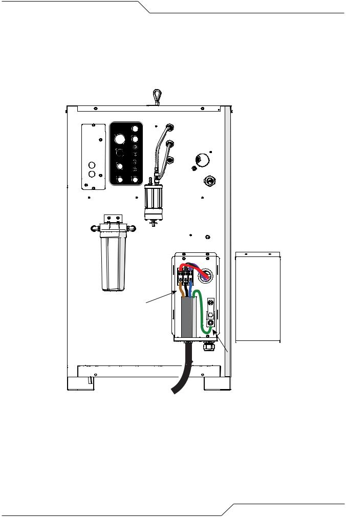
1.Remove the input power cover to the right of the coolant filter at the rear of the power supply. To do this remove the two screws then lift up and pull away.
2.Carefully cut back the outer sheath on the primary input power cable to expose the individual wires. Cut back the insulation on the individual wires. Route the cable upward through Input Power Port at the bottom of the panel. There are 2 extra plates included at the cable entrance. Discarding one or both allows changing the opening size for larger cable/strain relief.
|
USER INPUT |
|
|
HEIGHT CONTROL |
|
J15 - CNC |
AIR / O2 |
N2 / H35 |
PLASMA |
PLASMA |
|
|
CB2 - 5A 120 VAC |
|
|
CB3 - 5A 24 VAC |
|
|
CB4 - 5A 120 VAC |
|
F1 - 8A SB 230 VAC |
F2 - 8A SB 230 VAC |
|
Input Power
Art # A-11949
3.Install stripped end of 3 phase wires into the terminal block L1, L2 and L3 and connect the individual cables as shown.
Manual 0-5335 |
INSTALLATION |
3-5 |
PAK 200i
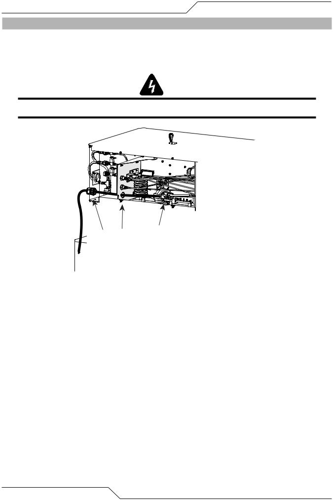
3.06 Connect Work Cable
1.Refer to the illustration below. Pass the end of the work cable through the cord grip at the back of the power supply rear panel, then through the bottom opening in the bulkhead panel.
2.Refer to the illustration below. Connect the lead to the bolt in the first hole on the bus bar as shown. Tighten securely. Do not overtighten.
WARNING
Ensure that lead attachment hardware is properly sized. Excess length may cause damage if hardware contacts other parts of the system.
Art # A11951
|
INSTALLATION |
Manual 0-5335 |
Loading...