


ASPECT TA-890 SYSTEM
USER MANUAL
Turbosound Ltd.
Star Road, Partridge Green
West Sussex RH13 8RY United Kingdom
Tel: +44 (0)1403 711447 Fax: +44 (0)1403 710155
web: www.turbosound.com
Issue 1.3 © Turbosound Ltd, October 2005

user manual
TA-890
Contents |
|
EC Declaration of Conformity........................................................................................................................ |
6 |
Introduction .................................................................................................................................................... |
7 |
Turbosound Aspect System Concepts ..................................................................................................... |
7 |
The Turbosound Polyhorn™..................................................................................................................... |
7 |
Aspect TA-890 Turnkey System Concept...................................................................................................... |
9 |
The Loudspeaker Management System (LMS) Concept....................................................................... |
10 |
LMS-D24, LMS-D26 and LMS-D6 Loudspeaker Management Systems............................................... |
10 |
Amplifier Racks........................................................................................................................................ |
10 |
Power Amplifiers..................................................................................................................................... |
10 |
Digital Controllers ................................................................................................................................... |
11 |
Aspect Loudspeaker Components.......................................................................................................... |
11 |
TA-890L Low Frequency Enclosure ........................................................................................................ |
11 |
TSW-218 Subwoofer ............................................................................................................................... |
12 |
TA-890H Mid-high Enclosure.................................................................................................................. |
12 |
Transportation ......................................................................................................................................... |
14 |
Aspect Flying Systems............................................................................................................................ |
15 |
Flying and Stacking...................................................................................................................................... |
16 |
Overview.................................................................................................................................................. |
16 |
GigMate™ Acoustic Simulation .................................................................................................................. |
17 |
TA-890 user manual Page 2

|
user manual |
|
TA-890 |
Setting up a Venue - Overview............................................................................................................... |
17 |
Running Turbosound GigMate™ / EASE Focus for the first time: ....................................................... |
18 |
Designing a system ................................................................................................................................. |
20 |
Changing the system .............................................................................................................................. |
23 |
Safety Notes on Rigging ......................................................................................................................... |
25 |
Sample Certificate of Load Test ............................................................................................................. |
26 |
Flying Hardware ...................................................................................................................................... |
27 |
Wide and Narrow Flybar Settings .......................................................................................................... |
27 |
Figure 1. Single A-System Flybar FB-890/1A ......................................................................................... |
28 |
Figure 2. Double A-System Flybar FB-890/2A........................................................................................ |
29 |
Figue 3. Triple ‘A’ System Flybar FB-890A/3W ...................................................................................... |
30 |
FC-890 Flying Chains............................................................................................................................... |
31 |
TS-890 Tilting Straps............................................................................................................................... |
31 |
Three-wide hang using MB-890, EB-890, FB-890/2A and FB-890/1A .................................................... |
32 |
Four-wide hang using MB-890 and FB-890/2A ...................................................................................... |
33 |
Integral Flying Hardware ........................................................................................................................ |
34 |
‘A’ System Flygear .................................................................................................................................. |
34 |
1. Drop Link.............................................................................................................................................. |
35 |
2. Swing Latch ......................................................................................................................................... |
35 |
Connecting Flying Chains to the Cabinet............................................................................................... |
35 |
Figure 1 – insert cabinet link Figure 2 – release swing latch............................................................. |
35 |
Connecting Cabinets - ‘A’ System.......................................................................................................... |
35 |
Setting Vertical Angles – ‘A’ System...................................................................................................... |
36 |
Attaching the Tilt Straps ......................................................................................................................... |
37 |
Turbobass Directivity .............................................................................................................................. |
38 |
Bass Enclosure arraying.......................................................................................................................... |
38 |
Aiming - directivity of the stack.............................................................................................................. |
38 |
The typical Left to Right problem........................................................................................................... |
40 |
Creating Directional Bass arrays: ........................................................................................................... |
41 |
Bass in a line:........................................................................................................................................... |
41 |
Fanned bass............................................................................................................................................. |
42 |
Bessel Array............................................................................................................................................. |
43 |
General observations of long lines of bass ........................................................................................... |
43 |
End firing array........................................................................................................................................ |
44 |
Summing up............................................................................................................................................ |
45 |
Ground stacking ...................................................................................................................................... |
46 |
LMS SERIES Loudspeaker Management SystemS .................................................................................... |
47 |
TA-890 user manual Page 3

user manual
TA-890
Introduction ............................................................................................................................................. |
47 |
General features & facilities.................................................................................................................... |
47 |
Unpacking................................................................................................................................................ |
47 |
Mechanical Installation ........................................................................................................................... |
47 |
LMS-D6 Front Panel Functions ............................................................................................................... |
48 |
LMS-D6 Rear Panel Functions ................................................................................................................ |
49 |
Mains Power ............................................................................................................................................ |
49 |
Voltage Setting ........................................................................................................................................ |
50 |
Safety Earthing ........................................................................................................................................ |
50 |
AC Power Fusing ..................................................................................................................................... |
50 |
Powering Up............................................................................................................................................ |
50 |
Audio Connections .................................................................................................................................. |
51 |
Input and Output Connector Wiring....................................................................................................... |
51 |
Time correction for loudspeaker driver placement ............................................................................... |
51 |
LMS-D24 and D26 LOUDSPEAKER MANAGEMENT SYSTEMS................................................................ |
52 |
Features ................................................................................................................................................... |
52 |
Front Panel Functions ............................................................................................................................. |
53 |
Rear Panel Functions............................................................................................................................... |
55 |
Operating the LMS-D24 and D26................................................................................................................. |
56 |
Starting up ............................................................................................................................................... |
56 |
Selecting a Factory Preset....................................................................................................................... |
56 |
Creating a Crossover............................................................................................................................... |
56 |
Navigation and Viewing Parameters...................................................................................................... |
57 |
Navigation................................................................................................................................................ |
58 |
Preset Recall ............................................................................................................................................ |
59 |
Preset Store ............................................................................................................................................. |
60 |
DSP Processing Layout................................................................................................................................ |
61 |
Input DSP block diagram ........................................................................................................................ |
61 |
Output DSP block diagram ..................................................................................................................... |
61 |
Stereo / Mono Formats ........................................................................................................................... |
61 |
DSP processing ............................................................................................................................................ |
62 |
Input Channels......................................................................................................................................... |
62 |
Parametric Equalisation .......................................................................................................................... |
64 |
High and Low shelving filters ................................................................................................................. |
64 |
Parametric filters ..................................................................................................................................... |
64 |
Output Channels .......................................................................................................................................... |
65 |
Gain and Polarity..................................................................................................................................... |
65 |
Delay ........................................................................................................................................................ |
65 |
High and Low Pass Filters....................................................................................................................... |
66 |
Parametric Equalisation .......................................................................................................................... |
67 |
Limiters .................................................................................................................................................... |
68 |
Routing..................................................................................................................................................... |
68 |
Utilities.......................................................................................................................................................... |
69 |
TA-890 user manual Page 4

|
user manual |
|
TA-890 |
Utility functions ....................................................................................................................................... |
69 |
Rear Panel Functions............................................................................................................................... |
70 |
AMP-890 Aspect System Amplification Rack ............................................................................................. |
71 |
Racking, Cables and Connections .......................................................................................................... |
71 |
Options..................................................................................................................................................... |
72 |
Input Connections ................................................................................................................................... |
72 |
Figure 1. Amplifier Rack Signal Wiring.................................................................................................. |
73 |
Output Connections ................................................................................................................................ |
73 |
Figure 2. Mid-High Outputs .................................................................................................................... |
74 |
Figure 3. Bass Outputs ............................................................................................................................ |
74 |
Break-out Cables – NL4 bass .................................................................................................................. |
75 |
Break-out cables – NL8 mid-high............................................................................................................ |
76 |
Extension Cables ..................................................................................................................................... |
76 |
Mains Connections.................................................................................................................................. |
77 |
T-25 and T-45 High Efficiency Audio Power Amplifiers............................................................................. |
78 |
General Features & Facilities.................................................................................................................. |
78 |
Front Panel Functions T-25 ..................................................................................................................... |
79 |
Front Panel Functions T-45 ..................................................................................................................... |
80 |
Mechanical Installation ........................................................................................................................... |
81 |
Mains Power............................................................................................................................................ |
81 |
Powering Up............................................................................................................................................ |
81 |
Safety Earthing........................................................................................................................................ |
81 |
Voltage Setting........................................................................................................................................ |
82 |
Voltage Range ......................................................................................................................................... |
82 |
Audio Connections & Controls ............................................................................................................... |
82 |
Polarity..................................................................................................................................................... |
83 |
Input Impedance...................................................................................................................................... |
83 |
Gain and Sensitivity Settings ................................................................................................................. |
83 |
Attenuation & Gain Setting .................................................................................................................... |
84 |
Output Connections ................................................................................................................................ |
84 |
Damping Factor ....................................................................................................................................... |
84 |
Long Speaker Lines ................................................................................................................................. |
85 |
The Cooling System ................................................................................................................................ |
85 |
Maintenance................................................................................................................................................. |
86 |
To rotate the horn moulding from ‘A’ mode to ‘B’ mode..................................................................... |
87 |
To rotate the horn moulding from ‘B’ mode to ‘A’ mode..................................................................... |
88 |
Removal of the high frequency driver ................................................................................................... |
88 |
Removal of the high-mid frequency driver............................................................................................ |
89 |
Removal of the low-mid frequency drive units ..................................................................................... |
90 |
General Maintenance .............................................................................................................................. |
90 |
Flying hardware....................................................................................................................................... |
90 |
Paintwork ................................................................................................................................................. |
91 |
Technical Specifications .............................................................................................................................. |
93 |
Warranty....................................................................................................................................................... |
94 |
|
TA-890 user manual |
|
Page 5 |

user manual
TA-890
EC DECLARATION OF CONFORMITY
Manufacturer
Turbosound Ltd
Star Road, Partridge Green, West Sussex, RH13 8RY, UK
Products
T-25 Power Amplifier
T-45 Power Amplifier
LMS-D6 Loudspeaker Management System
LMS-D24 & LMS-D26 Loudspeaker Management System
Standards |
|
Safety |
EN60065:2003 |
Relevant Specifications used as basis for tests |
EN66103-1:1996 |
|
EN55103-2:1996 |
Category
Professional apparatus for use in Commercial Light Industrial and controlled EMC environments.
CE Marking
All products are marked in accordance with the relevant statutory requirements.
TA-890 user manual Page 6
user manual
TA-890
INTRODUCTION
Turbosound Aspect System Concepts
The TA-890 system is a modular point source loudspeaker system designed to deliver extremely high fidelity audio. The system is easily scaleable from large and medium scale concert touring applications to small clubs and events.
The Aspect system concept centres around the exceptional directivity of the patented Polyhorn™ devices employed in the high frequency and high-mid frequency sections of the mid/high enclosure. In contrast to the majority of conventional horns, the Polyhorns develop a more consistent frequency response across all seats of an auditorium with minimal interference between adjacent enclosures.
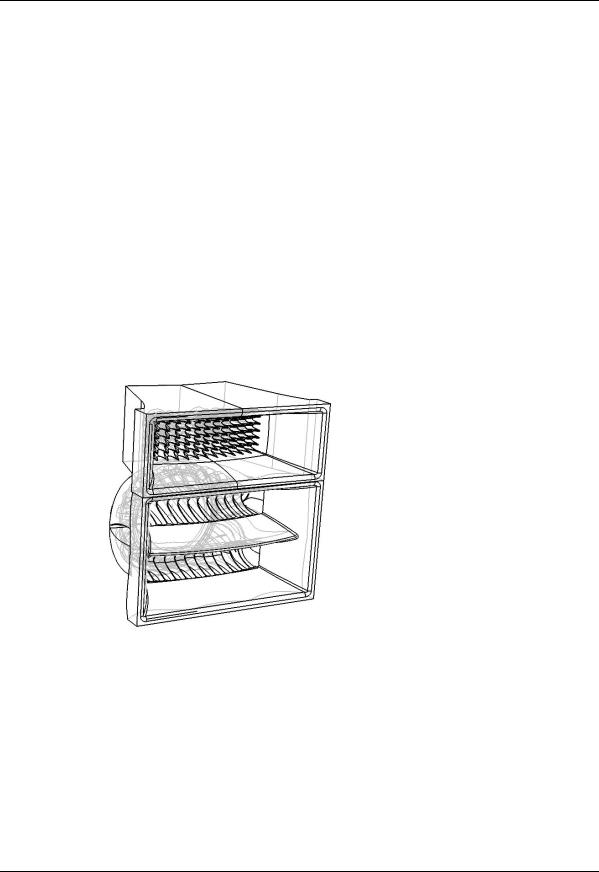
The Turbosound Polyhorn™
The patented Polyhorn™ devices – employed in both the high frequency and high-mid frequency bands – exhibit a sharp cut-off at the edges of the dispersion pattern, making it possible to produce seamless coverage of a venue with minimal destructive interference between elements, however many individual enclosures are deployed in the cluster. The Polyhorn™ devices generate a phase-coherent and smoothly-curved wavefront which matches the array curvature, whose centre becomes the virtual point source.
TA-890 user manual Page 7
user manual
TA-890
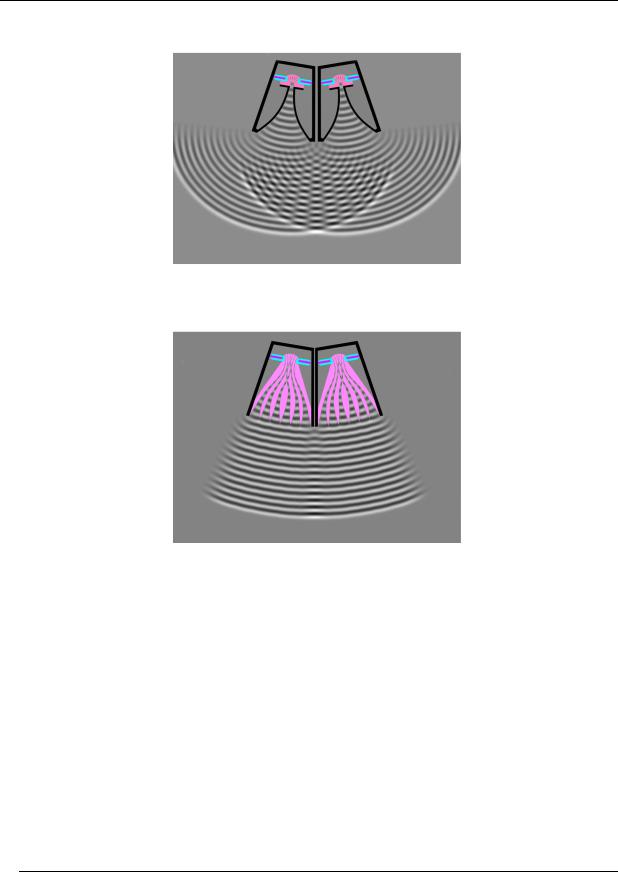
Conventional HF horns produce destructive interference
Poyhorn™ - smoothly curved wavefront
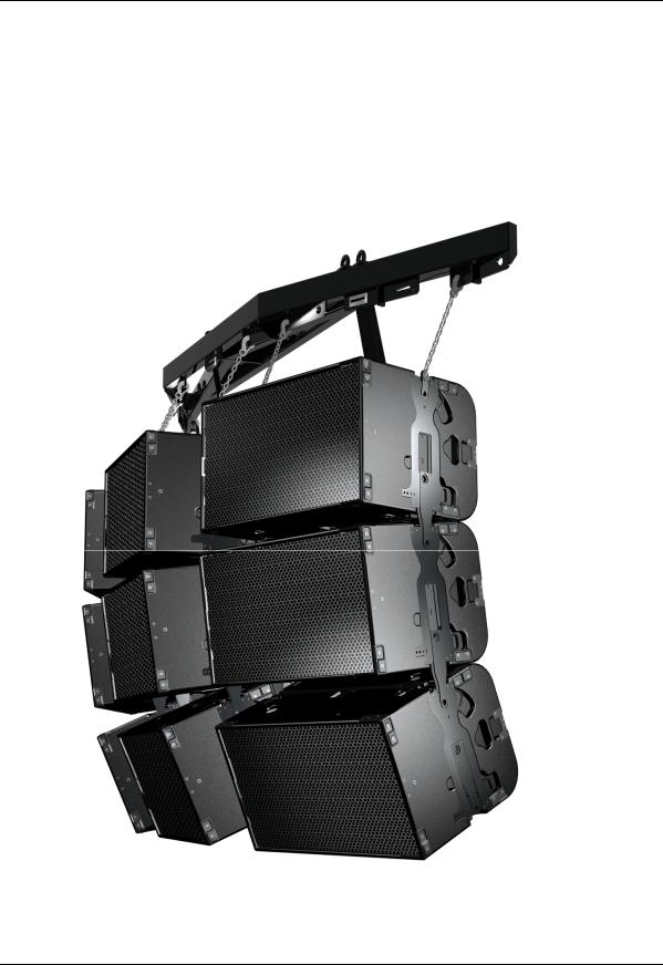
The TA-890H mid-high enclosure forms the main component of flown clusters, and can be orientated either horizontally or vertically (the mid/high section pictured above is square and rotatable) in order to match venue specifics such as rigging height and audience sightline restrictions. It can also be usefully employed as a front or side fill cabinet.
The TA-890L low frequency enclosure can either be integrated in a flown cluster with TA890H enclosures, due to its identical size and flying hardware, or can be ground stacked.
TA-890 user manual Page 8

user manual
TA-890
ASPECT TA-890 TURNKEY SYSTEM CONCEPT
Aspect is available as an integrated audio system package, comprising loudspeakers with integral flying hardware, amplifier racks and all necessary drive and control equipment in an extremely compact and manageable form. In addition, the system has been designed to truck pack efficiently and handle easily.
The concept of assembling a system around standardised components ensures absolute compatibility between users, although sufficient flexibility is built into the rack design to allow for varying requirements such as the ratio of bass cabinets to mid-highs, or 4-way or 5- way operation. Aspect systems from different sources may therefore be freely combined without difficulty. This provides owners with a considerable competitive advantage in servicing the requirements of international touring productions, and in co-operating with other Aspect suppliers within the worldwide network.
The controller functions as an electronic loudspeaker management system, comprising a 24dB per octave crossover, with factory preset limiters matched to the power amplifiers, digital time-alignment and electronically balanced inputs and outputs.
A standard Aspect integrated sound system consists of:
•TA-890H mid-high enclosures
•TA-890L low frequency enclosures
•Flybars, adjustable flying chains and flybar trunk
•Loudspeaker break-outs and multi-way extensions
•Multi-way returns system
•LMS-D6 or LMS-D26 system controllers
•AMP-890 ampifier racks with:
o T-45 and T-25 power amplifiers
o Three phase 32A power distribution
O Multi-way and local speaker connections
TA-890 user manual Page 9

user manual
TA-890
The Loudspeaker Management System (LMS) Concept
Turbosound Loudspeaker Management Systems are more than just electronic crossovers. They provide full digital alignment of all components in the Aspect enclosures, to ensure coherent acoustic output. They also incorporates a number of features which contribute to overall system reliability and ease of setting-up.
All system parameters such as crossover frequencies, limiter settings and equalisation can be simply called up from a factory-set menu, making it possible to maintain consistent and repeatable system performance.
Because the power amplifiers are included as part of the Aspect system, the controllers are able to utilise output limiters which are precisely matched to the system requirements, being pre-set to prevent the amplifiers from clipping. Inputs and outputs are fully balanced, providing isolation between the controller and the amplifier inputs. These factors contribute to high reliability in the adverse circumstances often encountered under arduous touring conditions.
LMS-D24, LMS-D26 and LMS-D6 Loudspeaker Management Systems
Use of the LMS-D2X and LMS-D6 loudspeaker management systems ensures accurate timealignment of the system drive units and also provides a facility for users to select additional delay, either to compensate for physical displacement of ground-stacked bass enclosures relative to flown high packs, or to provide full range delay for correct image localisation or use in distributed systems. It should however be noted that the high-Q, and therefore long throw, properties of the Aspect system generally eliminates the need for distributed delayed systems, even for very large audiences.
Amplifier Racks
Aspect amplifier racks are fully loaded and fully equipped for the most demanding concert touring applications. They are fitted as standard with two T-25 model amplifiers and three T- 45 model amplifiers, Socapex speaker break-outs as well as local connectors, single phase or three phase mains distribution, and multi-way signal input and link connectors. All the component parts are rigidly mounted in a 12U steel space frame with removeable panels, and housed in a road case with heavy duty wheels.
Power Amplifiers
In addition to the Turbosound T-25 and T-45 model amplifiers supplied with turnkey Aspect systems, the following other power amplifier brands provide sufficient performance and mechanical compatibility to perform well with Aspect loudspeaker systems:
TA-890 user manual
Page 10
user manual
TA-890
•MC2 E series
•Lab Gruppen FP series
•Crest Pro series
•QSC Powerlight II series
Digital Controllers
In addition to the Turbosound LMS-D6 and LMS-D26 loudspeaker management systems, the following digital crossovers have been tested and are recommended for use with Aspect systems:
•BSS FDS366
•XTA DP224, DP226 and DP428
Aspect Loudspeaker Components
All the drive units have been designed in-house specifically for the Aspect system and are manufactured exclusively for Turbosound. This means that they are expressly suited to their intended purpose, and make use of innovative features to ensure premium performance.
Neodymium magnets are used throughout all drive units. This results in higher efficiency, less power compression and reduced overall weight. Low-mid frequency drivers are designed to be rear-facing in the enclosure, enabling the heatsink / phase plug to be placed in the air flow to aid cooling.
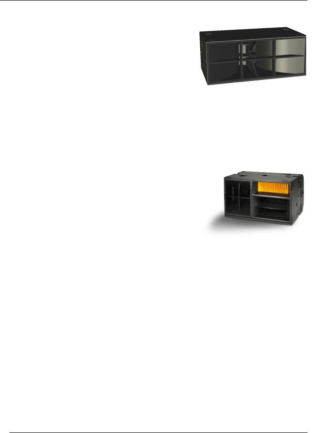
TA-890L Low Frequency Enclosure
The TA-890L low frequency enclosure covers the low frequency range from 35Hz up to 100Hz. It contains two very high power 15" neodymium drive units loaded with TurboBass™ devices. The TA-890L is a very compact enclosure, identically sized to the TA-890H, and its minimal size and low weight ensures easy handling. It is designed to provide beneficial low frequency coupling when used in multiples. The enclosure
may be ground-stacked or flown using its integral flying hardware.
TA-890 user manual
Page 11
user manual
TA-890
TSW-218 Subwoofer
The TSW-218 is designed to cover the sub and low frequency ranges from 25Hz to 100Hz, and can be used as part of a 5-way Aspect system in order to reinforce sub-bass frequencies. It utilises two custom designed neodymium 18” drivers loaded with TurboBass™ devices. The proprietary loading technique and horn flare design produces significant mutual coupling between adjacent enclosures, resulting in
sensitivity gains of up to 110dB with eight units coupled.
TA-890H Mid-high Enclosure
The TA-890H enclosure covers frequencies above 100Hz and contains a total of five drive units. A pair of 10” neodymium low-mid frequency drivers loaded with TurboMid™ devices covers the frequency range from 100Hz to 400Hz. The low-mid drivers are rearfacing in the enclosure, providing not only additional cooling by placing the magnet/heatsink assemblies in the path of the airflow, but also acting as phase plugs. A specially developed 10” low-mid driver
loaded with a LMF Polyhorn™ device covers the range from 400Hz to 4kHz. The remaining frequencies are covered by a pair of 50mm dome drivers loaded with Polyhorn™ waveguides specifically designed for this purpose.
The TA-890H mid-high enclosure is designed to provide a precise array angle of 25º horizontal x 15º vertical. This high Q provides the projection necessary for true long throw applications such as large arena and outdoor productions.
The Polyhorn™ and TurboMid™ devices are unique to Turbosound and are covered by principle patents world-wide. They utilise specialised forms of horn loading which provide exceptionally low distortion and high efficiency from cone-type drive units. The subjective effect of these devices is greater clarity and transparency of reproduction when compared with conventional compression drivers and horns.
The TA-890H is fully equipped for all touring applications with independent flying systems. This allows cabinets to be configured horizontally providing considerable flexibility of use.
TA-890 user manual
Page 12

user manual
TA-890
It includes a hinged rear access door, integral multi-way speaker cable, removable wheel board, ergonomically placed flush handles, weatherised beech plywood construction and optimised truck-pack dimensions. The TA-890H enclosure is exactly the same size as, and of very similar weight to, the TA-890L.
TA-890 user manual Page 13
user manual
TA-890
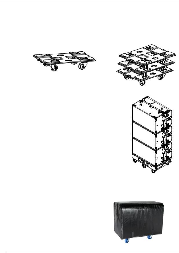
Transportation
TA-890 cabinets include a removable wheelboard which clips to the front of the cabinet, allowing single units to be conveniently transported. These are designed to be stackable, so that when not in use they can be neatly stored without taking up floor space. The wheelboards will fit both mid-high and low frequency cabinets.
Up to three TA-890 cabinets can be stacked on a WB890 wheel dolly, and this allows the cabinets to be pre-configured and locked at the warehouse using the integral flygear. Cabinets can then be wheeled in or out of a truck straight on to a stage area ready to be flown. The stack is stabilised by ratchet straps which attach to the flygear on the top cabinet and are tightened by means of recessed levers on the wheel dolly.
Optional heavy duty transit covers are available for TA-890 cabinets. These fasten at the front of the cabinet with velcro straps.
TA-890 user manual Page 14
user manual
TA-890
Aspect Flying Systems
To take full advantage of the very precise dispersion properties of the Aspect system, an integral rigging system has been developed. The flying system is inherently safe, flexible and simple to use, and even though it is integral to the box, it may be quickly and easily removed for safety testing. The rigging design allows the creation of clusters and arrays that can be assembled quickly and with a minimum number of crew, and with full control of the angles between enclosures and of their vertical inclination, to suit a wide variety of requirements.
TA-890 user manual Page 15

user manual
TA-890
FLYING AND STACKING
Overview
The Aspect system flying hardware is specifically designed to take advantage of the precise horizontal directivity characteristics, as well as allow a wide range of adjustment of the vertical angles between adjacent enclosures, and the overall vertical inclination of each column of enclosures. This means that arrays can easily be optimised to suit the coverage requirements of any situation.
Sound radiating from adjacent cabinets will successfully blend over a range of included angles, creating a coherent point-source image, and this results in the ability to tailor both the overall coverage and the SPL at a given distance.
The concept of arraying the TA-890 Aspect system is to create part of the surface of a sphere. A small part of a large sphere will form a high-directivity (long-throw) system with a high SPL at a distance, whereas a large part of a small sphere will be of lower directivity producing less SPL at a distance, but having a wider angle of coverage. This approach leads to the creation of a virtual point source behind the array, where sound appears to emanate from a single point in space.
There are some simple rules to follow to help achieve this goal:
•Obtain a smooth even curve in the horizontal plane.
•Use a similar amount of tilt on each column.
•Ensure that the bottom corners of each column are in line with each other.
TA-890 user manual Page 16

user manual
TA-890
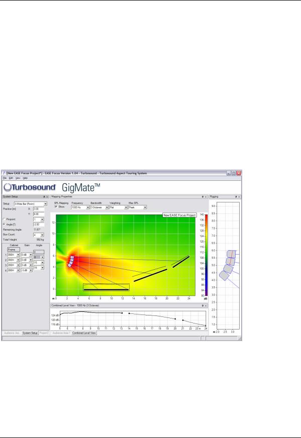
GIGMATE™ ACOUSTIC SIMULATION
While the Aspect System is remarkably intuitive in terms of building arrays and aiming them, and requires no theoretical calculations in order to achieve optimum coverage of a room or audience space due to its inherent ‘point-and-shoot’ nature, there may well be situations where some prior knowledge of a venue can save time in setting up and configuring the PA. In order to aid in this process, Turbosound offers the GigMate™ software acoustic simulation package, a version of the generic EASE Focus program that is based on current EASE 4.1 data.
GigMate™ provides an accurate elevation representation of sound pressure level and coverage of a room, given the dimensions of the audience areas and location of available rigging points in the venue. The database allows for flown clusters of TA-890 touring or TA880 trapezoidal enclosures, or for ground stacked arrays.
Setting up a Venue - Overview
The Audience Area window provides a way add or remove Audience Areas and define their location in the space. A venue can be selected from a range of standard venue presets or set up from scratch using the X and Y co-ordinates menus to define the location, size and angle of the listening areas.
The PA is set up by choosing either a flown cluster or ground stack. Box count, cluster position, tilt angle and splay angle can all be selected independently.
The mapping properties allow the user to select frequency bands from 100Hz to 10kHz and also bandwidth from one-third octave to broadband.
Once mapped to achieve satisfactory room coverage and level, results can be saved and printed as a .rtf file. The program will also calculate the total weight of the cluster as well as its overall physical size.
TA-890 user manual Page 17
user manual
TA-890
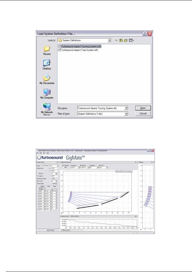
Running Turbosound GigMate™ / EASE Focus for the first time:
When you first start the program you must set the system file that it is to use. The installation files include two Turbosound Aspect System files as shown below:
Select the Touring version cabinets. You will now be presented with the GigMate™ main screen.
TA-890 user manual Page 18

user manual
TA-890
The screen is split into four main areas:
System Setup
The left hand side of the screen is where you define the system, auditorium and project. Tabs On the bottom of this window allow you to toggle between modes.
Mapping Properties
This is the main window which will display the system as configured in the System Setup window along with the audience areas and mappings.
Audience Area
Beneath the main Mapping Properties window this graphically displays the SPL on each audience area, or across a combination of audience areas.
Rigging
The far right window shows the detail of the system configuration and is especially useful in larger venues where the speakers shown in the main window become very small.
TA-890 user manual Page 19
user manual
TA-890
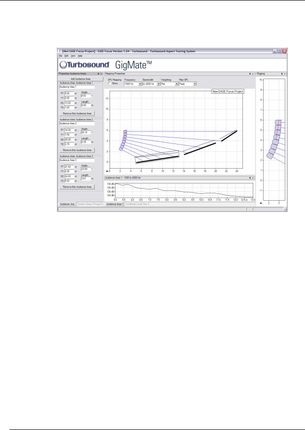
Designing a system
To design a system begin by defining the venue/audience areas by clicking on the “Audience Area” tab in the bottom left of the screen.
Within this window you can edit or remove existing audience areas, and create new ones.
There are two methods of defining an audience area. In either case you must define the X1/Y1 coordinate of the start of the area, you can then either enter the X2/Y2 points or its length and angle.
As you create audience areas they are shown graphically in the main window.
The next step is to design the loudspeaker array using the “System Setup” window. Select the “System Setup” tab in the bottom left of the screen and begin by choosing the desired flybar or groundstack in the drop down box at the top left of the window.
TA-890 user manual Page 20
user manual
TA-890
Now select the number of cabinets deep that you wish to hang or stack from the “Box Count” drop-down menu. Trim height, or PA wing height can now be set in the “Position” field.
If a mix of Low and High cabinets are to be used then select in the “Cabinet” window the type and location in the array of each box. The angle between cabinets can now be set in the “Angle” list. Each cabinet has an aiming line that can be used to determine the centre of each cabinet’s dispersion. Adjust the trim height, top angle and inter-cabinet angle to achieve optimum coverage.
TA-890 user manual Page 21
user manual
TA-890
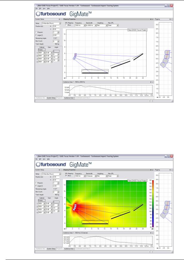
Now that the general design has been established the system performance must be mapped. At the top of the main window there is an “SPL Mapping” checkbox. This will map the system output at the frequency and bandwidth selected in the adjacent dropdown boxes. For most applications a one-third octave mapping gives realistic and useful data.
TA-890 user manual Page 22
user manual
TA-890
The Audience Area graph at the bottom of the window shows the SPL, as specified in the SPL Mapping lists, on the selected Audience Area. The selected area is highlighted in the main window and the graph is repeated onto each area. Selecting the “Combined Level View” tab will show the SPL across all areas simultaneously.
Now that the system is mapped, the inter-cabinet angles or row attenuation may be trimmed to provide the smoothest coverage. Typically the bottom row of the system will require some attenuation and should be on it’s own “Amp way” to achieve this.
Changing the system
GigMate™ currently includes both the Aspect Touring TA-890 Series and the Trapezoidal TA880 series products. To switch between systems use Edit/Change System on the menu bar and select from the list.
TA-890 user manual Page 23

user manual
TA-890
Two typical examples are shown here.
theatre-style venue: 3-wide flown cluster @ 1kHz
Small arena system; 2-wide by 5 deep flown cluster @ 4kHz
TA-890 user manual Page 24

user manual
TA-890
Safety Notes on Rigging
The Turbosound TA-880 system has been designed and constructed to a high standard of safety, and tested to the most demanding of specifications with a safety factor of 13:1. Always wear protective headwear, footwear and eye protection in accordance with local regulations. Anyone involved in flying ANY sound system, especially in a touring capacity, should take note of the following advice:
The rigging of a flown sound system may be dangerous unless undertaken by qualified personnel with the required experience and certification to perform the necessary tasks. Fixing of hanging points in a roof should always be carried out by a professional rigger and in accordance with the local rules of the venue. The house rigger and/or building manager must always be consulted.
You should observe particularly the following points:
Inspect rigging systems and cabinets for damage before proceeding to assemble a flown array. If any parts are damaged or suspect, DO NOT USE THEM.
When initially ratcheting a column of speakers it is good to bear in mind the expected angle of inclination so as to avoid ending up with too much of the strap left on the ratchet. This is important because the ratchet can only take three complete turns before it releases itself.
WARNING: If a tilt strap is released suddenly, the column of enclosures may tend to swing violently forwards and care must be taken to avoid danger to persons in the vicinity. It is essential to check that nobody is standing immediately in front of the column, and to give a suitable warning, before the strap is released. Ideally, two persons should support the column from the side whilst the strap is released, or alternatively the bottom row may be returned to the ground before release. In any event it is essential that all personnel in the vicinity are aware that the system is about to move and that they must keep clear.
Aspect Flying System components have been individually tested in accordance with the following regulations:
The Health and Safety at Work Act 1974
The Supply of Machinery (Safety) Regulations 1992
The Lifting Operations and Lifting Equipment Regulations 1998
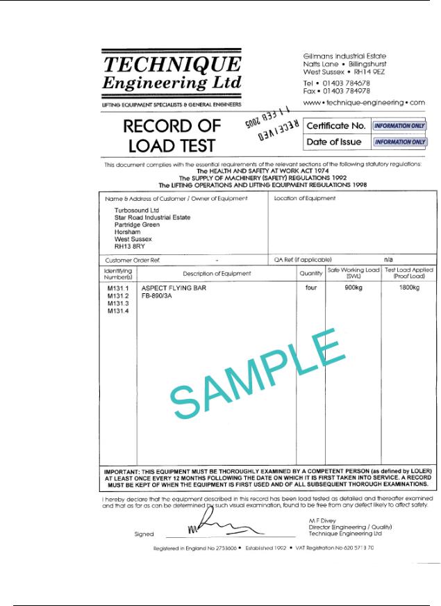
Each component is covered by a Record of Load Test Certificate, which may be obtained on request from Turbosound, quoting the indentifying number(s) from the flying equipment. A copy of a sample certificate is reproduced overleaf.
TA-890 user manual Page 25
user manual
TA-890
Sample Certificate of Load Test
TA-890 user manual Page 26

user manual
TA-890
Flying Hardware
The ‘A’ system flying bars consist as follows:
•Single bar – supports a vertical column of cabinets up to 8 deep.
•Twin bar – supports two vertical columns up to 8 deep.
•Triple bar – supports three vertical columns from a single pick-up point or with chain bridles, specifically designed for outdoor use with ground support towers
•Mother beam – used to connect multiples of single bars and/or twin bars in a modular fashion, allowing the creation of speaker clusters up to and including full 360° arrays.
•Extender beam – connects half a mother beam to a two-wide bar and a single bar, which can be bridled from one motor or picked up by two points
•Spacer bar – used to join and maintain the distance between flying bars.
Flying boxes in their horizontal format is simply achieved by suspending vertical columns of loudspeakers using chains attached to lifting points on the fixed angle flybars depicted below. Based on the predicted 25° of horizontal coverage from a single cabinet, it is an easy job to assess how many columns, and therefore which particular combination of flybars, will be needed to achieve the required coverage. The top chains are adjustable to allow the cluster to hang either close to the bar where trim height is critical, or further away when more radical kelp is applied to the columns. In addition, all flybar assemblies allow the user two options to vary the width at the flybar to accommodate deep arrays.
Wide and Narrow Flybar Settings
In order to accommodate the wide range of vertical coverage requirements dictated by a particular venue, all flybars - except the single bar - offer two sets of lifting points, enclosure attachment points and lifting strap points. The narrow setting is designed for a column of cabinets in the ‘A’ or horizontal orientation and will be more than adequate for the majority of applications. However, the wide setting provides the additional horizontal spacing at the flybar to allow for a vertical column of up to eight cabinets deep to be flown where more vertical coverage is called for. No additional parts or flybars are required to accommodate virtually all situations; it can all be achieved using only one type of flybar.
TA-890 user manual Page 27
user manual
TA-890
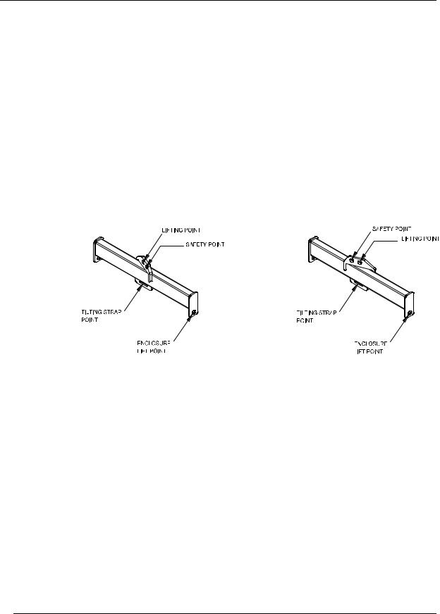
Figure 1. Single A-System Flybar FB-890/1A
The single flybar is fabricated from box steel section with integral lifting point, safety point, enclosure suspension tabs and tilting strap pick-up point, designed to fly a single box or vertical column of boxes up to eight deep. The bar can be flown from a single one-tonne motor.
Single bars are manufactured as left and rights units, and so can be used to combine in a modular fashion with double bars and mother beams to form part of larger configurations.
The net weight of the single flybar is 11kg.
FB-890/1A SINGLE FLY BAR (LEFT) |
FB-890/1A SINGLE FLY BAR (RIGHT) |
TA-890 user manual Page 28
user manual
TA-890
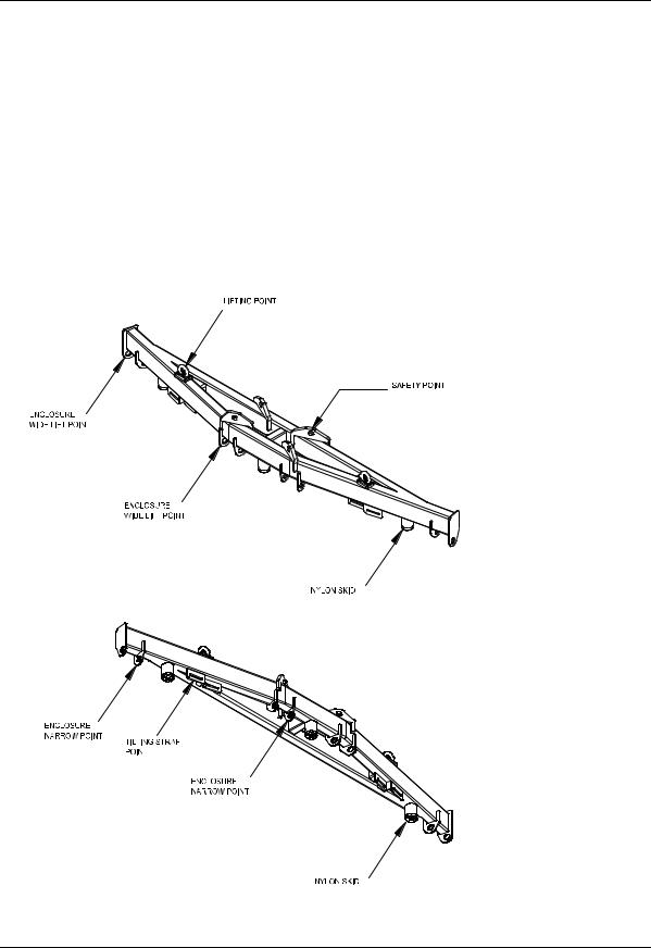
Figure 2. Double A-System Flybar FB-890/2A
A fixed angle double bar fabricated from box steel section and designed to fly two vertical columns of cabinets up to eight deep per column. It provides alternative cabinet suspension tabs and tilt strap points for narrow or wide configurations (when flying more than four boxes deep the wide configuration allows for the additional amount of kelp required), plus lifting points and safety points. A two-wide, six deep cluster can be flown from a single onetonne motor using a CB-890 chain bridle. Nylon skids are provided on the underside of the bar to ensure it is stable during transportation and handling, and to avoid accidental damage to the enclosure tabs.
The net weight of the bar is 42kg.
TOP VIEW
BOTTOM VIEW
TA-890 user manual Page 29
 Loading...