

Truxta BENDI 300G, BENDI 300D, BENDI 300E, BENDI 450E, BENDI 450G Owner's And Operator's Manual
...
OPERATOR MANUAL & PARTS LIST
MACHINE MODELS
BENDI 300G BENDI 300D BENDI 300E
BENDI 450G BENDI 450D BENDI 450E
SERIAL Numbers After B151040

Page 2
TABLE OF CONTENTS
Declaration of Conformity ...............................................................................3-7
Warning, Symbols & Decals …………………………………………………..………………..8
Machine Specification ………................................................................................9
General Safety / Health & Safety .................................................................10-11
Operating Instructions; - Petrol Diesel ........................................................12-13
(Pre-Start Checks, Start and Stop Procedures)
Service & Maintenance - Petrol & Diesel ....................................................... 14
Service - Pump Control Settings & Adjustment…..……………..……..…..……….. 15
Operating Instructions - Electric …………………………….…….……….....…….…….. 16
Operating Instructions - Battery Charger …………………...…….……..…..……….. 16
Warning, Symbols & Decals ............................................................................ 17
Service & Maintenance - Electric Problem Solving ……………..……..………..18-21
Parts Lists & Assembly
All Machines - Top Frame - Parts List …………………..…....……….….……..…. 22-23
All Machines - Front Chassis - Parts Lists ………………………...………...……...24-25
Petrol & Diesel - Rear Assembly - Parts Lists ………………...….....…...….....26-27
Electric - Rear Assembly - Parts List ………………………..….……..…..….…….28-29
Attachments - Flat Bed - Tow-Ball - Parts List ………………………….……….……...30
Warranty Registration ........................................................................................31

Page 3
We, Tufftruk Ltd, Sheen, nr. Buxton, Derbyshire, SK17 0EU, GB, hereby certify
that if the product described within this certificate is bought from an authorised
Tufftruk dealer within the EEC, it conforms to the following EEC directives:
2006/42/CE (This directive replaces directive 98/37/EC), Electromagnetic
Compatibility Directive 2004/108/CE (as amended by 89/336/EEC, 92/31/EEC
& 93/68 EEC).
The Waste Electrical and Electronic Equipment (WEEE) 2002/96/CE, the low
voltage directive 2006/95/CE, BS EN ISO 12100-1:2003 Safety of machinery and
associated harmonised standards, where applicable.
Noise emissions conform to directive 2000/14/EC Annex VI, for machines under
article 12 the notified body is AV Technology Limited, AVTECH House, Birdhall
Lane, Cheadle Heath, Stockport, Cheshire, SK3 0XU, GB.
Noise Technical Files are held at the Tufftruk Head Office address stated above.
DECLARATION OF CONFORMITY

Page 4
DECLARATION OF CONFORMITY
EC DECLARATION OF CONFORMITY
We
TUFFTRUK Ltd
The Croft, Sheen, Buxton, Derbyshire, SK170EU
Declare that the following equipment conforms to the Directive: 2000/14/EC (as amended) of the European Parliament and of the council on the
approximation of the laws of the Member States relating to the
Noise Emission in
the Environment by Equipment for Use Outdoors.
Equipment Category: Pedestrian Power Barrow
Product Name/Model: TRUXTA
Type/Serial No: B300D & B450D & R300D
The technical documentation is held by: TUFFTRUK Ltd Address above
The conformity assessment procedure followed was in according with annex VI
of the Directive.
Notified Body: AV Technology Ltd SK9 3RW
Measured Sound Power Level: 97 dB (LWA)
Guaranteed Sound Power Level: 100 dB (LWA)
A copy of this certificate has been submitted to the European Commission and to
EU Member State, United Kingdom
Place of Declaration: TUFFTRUK Ltd SK17 0EU
Date: 29/09/2014
Signed by: Ronald Blackhurst
Position in Company:. Managing Director
Name and address of manufacturer or Authorised representative: Tufftruk Ltd SK17 0EU

Page 5
DECLARATION OF CONFORMITY
EC DECLARATION OF CONFORMITY
We
TUFFTRUK Ltd
The Croft, Sheen,Buxton,Derbyshire,SK170EU
Declare that the following equipment conforms to the Directive: 2000/14/EC (as
amended) of the European Parliament and of the council on the approximation
of the laws of the Member States relating to the
Noise Emission in the
Environment by Equipment for Use Outdoors.
Equipment Category: Pedestrian Power Barrow
Product Name/Model: TRUXTA
Type/Serial No: B300G & R300G
The technical documentation is held by: TUFFTRUK Ltd Address above
The conformity assessment procedure followed was in according with annex VI
of the Directive.
Notified Body: AV Technology Ltd SK9 3RW
Measured Sound Power Level: 91 dB (LWA)
Guaranteed Sound Power Level: 94 dB (LWA)
A copy of this certificate has been submitted to the European Commission and to
EU Member State, United Kingdom
Place of Declaration: TUFFTRUK Ltd SK17 0EU
Date: 29/09/2014
Signed by: Ronald Blackhurst
Position in Company:. Managing Director
Name and address of manufacturer or Authorised representative: Tufftruk Ltd SK17 0EU

Page 6
DECLARATION OF CONFORMITY
EC DECLARATION OF CONFORMITY
We
TUFFTRUK Ltd
The Croft, Sheen, Buxton, Derbyshire, SK170EU
Declare that the following equipment conforms to the Directive: 2000/14/EC (as amended) of the European Parliament and of the council on the
approximation of the laws of the Member States relating to the
Noise Emission in
the Environment by Equipment for Use Outdoors.
Equipment Category: Pedestrian Power Barrow
Product Name/Model: TRUXTA
Type/Serial No: B450G
The technical documentation is held by: TUFFTRUK Ltd Address above
The conformity assessment procedure followed was in according with annex VI
of the Directive.
Notified Body: AV Technology Ltd SK9 3RW
Measured Sound Power Level: 93 dB (LWA)
Guaranteed Sound Power Level: 96 dB (LWA)
A copy of this certificate has been submitted to the European Commission and to
EU Member State, United Kingdom
Place of Declaration: TUFFTRUK Ltd SK17 0EU
Date: 29/09/2014
Signed by: Ronald Blackhurst
Position in Company:. Managing Director
Name and address of manufacturer or Authorised representative: Tufftruk Ltd SK17 0EU

Page 7
DECLARATION OF CONFORMITY
EC DECLARATION OF CONFORMITY
We
TUFFTRUK Ltd
The Croft, Sheen, Buxton, Derbyshire, SK170EU
Declare that the following equipment
conforms to the Directive: -
2000/14/EC (as amended)
of the European Parliament and of the council on the approximation of the laws of the Member States
relating to the
Noise Emission in the Environment by Equipment for Use Outdoors.
Equipment Category: Pedestrian Power Barrow
Product Name/Model: TRUXTA
Type/Serial No: B300E / B450E - ELECTRIC OPTIONS
The technical documentation is held by: TUFFTRUK Ltd Address above
The conformity assessment procedure followed was in according with annex VI of the Directive.
Notified Body: AV Technology Ltd SK9 3RW
Measured Sound Power Level: 69 dB
Guaranteed Sound Power Level: 69 dB
A copy of this certificate has been submitted to the European Commission and to EU Member State, United
Kingdom
Place of Declaration: TUFFTRUK Ltd SK17 0EU
Date: 29/09/2014
Signed by: Ronald Blackhurst
Position in Company:. Managing Director
Name and address of manufacturer or Authorised representative: Tufftruk Ltd SK17 0EU

Page 9
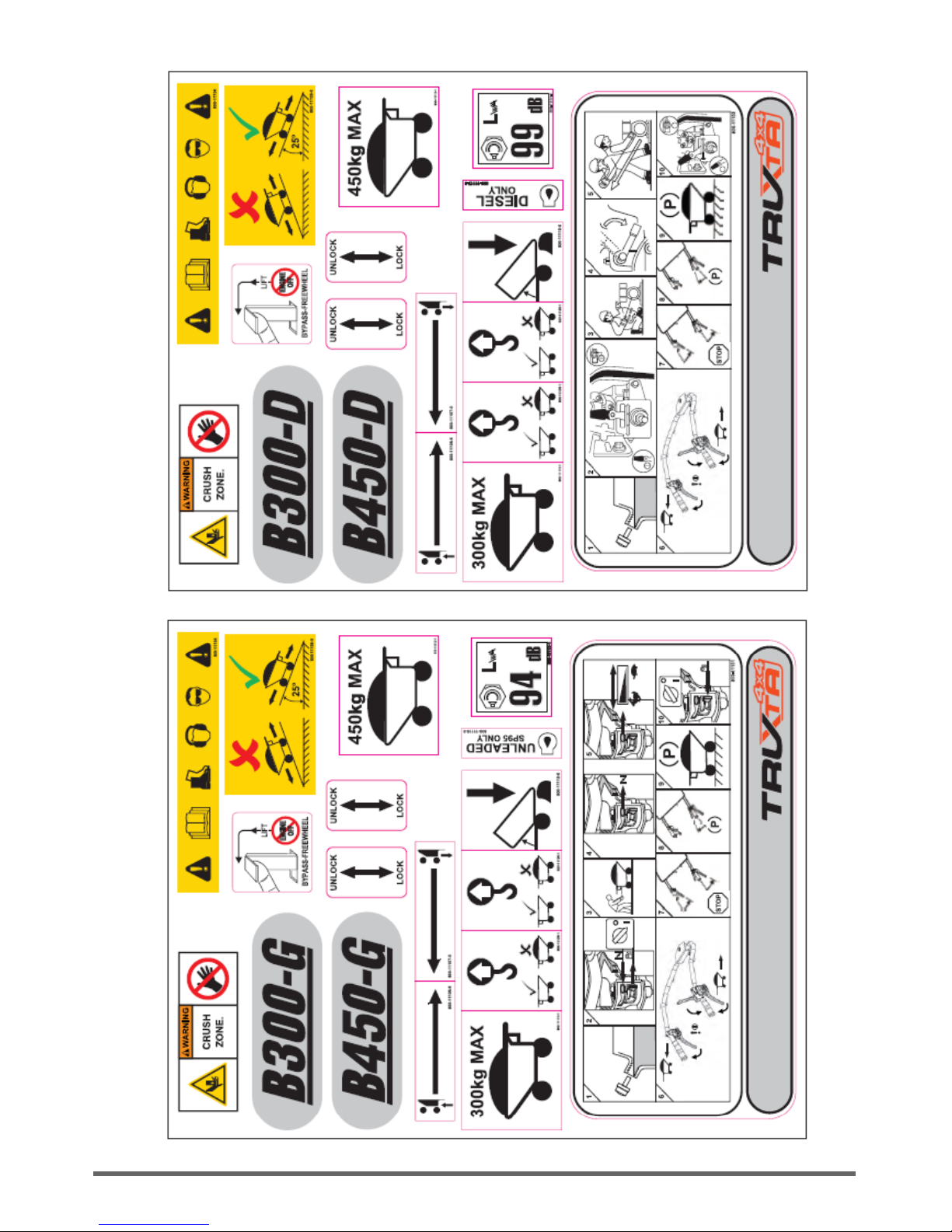
WARNING SYMBOLS & DECALS
TRUXTA BENDI - MACHINE SPECIFICATIONS
Model
Petrol B300G
(Petrol B450G)
Diesel B300D
(Diesel B450D)
Electric B300E
(Electric B450E)
Engine/Motor/Power
(kW)/hp
Honda GX 160 3.6 / 4.8
Honda GX200 4.1 / 5.5
Yanmar L48 3.5/ 4.7
Yanmar L48 3.5 / 4.7
DC Brushless
Motor 1000W /24v
Motor 1300W / 24v
Fuel Type
Unleaded Petrol (4 stroke)
Diesel 2 x 12v Batteries
Fuel Capacity
3.1 litres 2.5 litres
Max Payload (kg)
300kg / 7ft³ / 0.2m³
(450kg / 10.6ft³/ 0.3m³)
300kg /7ft³/ 0.2m³
(450kg / 10.6ft³/ 0.3m³)
300kg / 7ft³/ 0.2m³
(450kg / 10.6ft³ / 0.3m³)
Unladen Weight (kg)
170 (180)
201 (219) 224 (255)
Working Gradient
25° 25° 25°
Drive & Controls
Hydrostatic System 24v Motor Gearbox
Brake System
Fail-safe dead-man handle (International patents pending)
Standard Fitment Tyres
Flotation with option for turf tyres
Travel Speed
Fwd/Reverse
0-4 mph forward
0-1.5 mph reverse
0-3.5 mph forward
0-1.5 mph reverse
Noise Level (db.)
< 94 < 100 < 69
Hand Arm
Vibration
3.6 m/s²
4.6 m/s²
3.8 m/s²
3.8 m/s²
2.5 m/s²
2.5 m/s²
All dimensions unless otherwise stated are in mm.
We reserve the right to change specification without prior notice.
A 12 month warranty is applicable on all TRUXTA machines.

Page 10
GENERAL SAFETY
For your own personal protection and for the safety of those around you, please read and
ensure you fully understand the following safety information.
It is the responsibility of the operator to ensure that he/she fully understands how to operate
this equipment safely.
If you are unsure about the safe and correct use of the TRUXTA, consult your supervisor or
TRUXTA
This equipment is heavy and must not be lifted single-handedly, GET HELP and use suitable lifting
equipment.
Cordon off the work area and keep members of the public and unauthorized personnel at a safe distance.
Personal Protective Equipment (PPE) must be worn by the operator when ever this equipment is being used
(see Health & Safety).
Make sure you know how to safely switch this machine OFF before you switch it ON in case you get into
difficulty.
Always switch OFF the engine before transporting, moving it around the site or servicing it.
During use the engine becomes very hot; allow the engine to cool before touching it. Never leave the engine
running and unattended.
Never remove or tamper with any guards fitted, they are there for your protection.
Always check guards for condition and Security, if any is damaged or missing, DO NOT USE THE
TRUXTA until the guard has been replaced or repaired.
Do not operate the machine when you are ill, feeling tired, or when under the influence of alcohol or drugs.
Do not stand the machine on end with the engine running.
Do not use the TRUXTA to transport people.
Do not release the brake suddenly when travelling forward at speed with a heavy load as the machine may
topple forward.
(Brake off). Close the throttle if necessary so that engine braking controls the speed.
Always ensure that when moving downwards on a hill, the machine is travelling in reverse.
Before refuelling, switch off the engine and allow it to cool.
When refuelling, DO NOT smoke or allow naked flames in the area.
Spilt fuel must be made safe immediately, by using sand. If fuel is spilt on your clothes, change them.

VIBRATION
Some vibration from the operation is transmitted through the handle to the operator’s hands. DO NOT
exceed the maximum usage times. (See Technical Data section)
PPE (Personal Protective Equipment).
Suitable PPE must be worn when using this equipment i.e. Safety Goggles, Gloves, Ear Defenders, Dust
Mask and Steel Toe capped.
Footwear. Wear clothing suitable for the work you are doing. Tie back long hair and remove any
jewellery which may catch in the equipment’s moving parts.
Petrol And Diesel Machines.
Do not ingest fuel or inhale fuel vapours and avoid contact with your skin. Wash fuel splashes
immediately. If you get fuel in your eyes,
Irrigate with copious amounts of water and seek medical attention as soon as possible.
Exhaust Fumes
Do not operate the TRUXTA indoors or in a confined space, make sure the work area is adequately
ventilated.
Electric
Do not attempt to charge the electric machine if cable or connectors are damaged
Do not connect or disconnect the machine with wet hands immediately replace damaged charging parts
HEALTH AND SAFETY
Safe Disposal.
Instructions for the protection of the environment.
The machine contains valuable materials.
Take the discarded apparatus and accessories to the relevant recycling facilities.
ENVIRONMENT
Page 11

Page 12
OPERATING THE TRUXTA BENDI
1. Start the engine by putting the throttle to the run position and turning the ignition on.
(use choke if cold)
2. Grip the dead man lever and hold it down.
3. Use the forward and reverse levers to control direction of travel and speed.
Never press both levers at once or whilst the dead man is released as this will cause unnecessary
EMPTYING THE SKIP
1. Stop the machine by releasing the Drive Lever followed by releasing the dead man Brake Lever.
2. Once the machine has become stationary, pull the Skip Release Lever and the Skip will tip forwards
disposing of its contents.
3. When the Skip is empty, push back to its original position. The Skip will lock into place
PRE START UP INSPECTION
The following pre-start-up inspection must be performed before the start of each work session or after every
four hours of use, whichever is first.
Please refer to the service section for detailed guidance.
If any fault is discovered, the TRUXTA must not be used until the fault is rectified.
1. Thoroughly inspect the TRUXTA for signs of damage.
2. Check components are present and secure.
3. Check fluid lines, hoses filler openings, drain plugs and any other areas for signs of leakage.
Fix any leaks before operating.
4. Check the engine oil and fuel levels and top up as necessary.
5. Check the tyre pressures and top up as necessary.
6. Check for fuel and oil leaks.
Electric models
1. Check mains lead is stored correctly and is secured to the machine.
2. Check mains lead is not damaged in any way and replace as necessary.
OPERATING INSTRUCTIONS - PETROL AND DIESEL

Page 13
OPERATING THE PETROL TRUXTA B300G / B450G
Start the engine by putting the throttle to the run position and turning the ignition on.
(use choke if cold)
Grip the dead man lever and hold it down.
Use the forward and reverse levers to control direction of travel and speed. (Never press both
levers at once or whilst the dead man is released as this will cause unnecessary damage to the
machine.
Release the dead man to stop.
PETROL AND DIESEL - OPERATING INSTRUCTIONS
OPERATING THE L48 ELECTRIC START DIESEL TRUXTA B300D / B450D
Start the engine by turning the ignition key on. Move throttle to desired speed
Grip the dead man lever and hold it down.
Use the forward and reverse levers to control direction of travel and speed.
Never press both levers at once or whilst the dead man is released as this will cause
unnecessary damage to the machine.
TRANSMISSION BY-PASS FREEWHEEL FACILITY
This allows the Truxta to be moved without the engine running.
In the event of engine or drive belt failure it is possible to manually move the Truxta by lifting the by-pass
lever and locating to the left, then depress the yellow Deadman brake lever and the Truxta will now freewheel.
The By-pass lever is located next to the oil reservoir under the steering column.
THE BY-PASS LEVER MUST NOT BE LIFTED WITH THE ENGINE RUNNING.

SERVICE & MAINTENANCE - PETROL & DIESEL
Page 14
Hydrostatic Oil
Top up if oil is below minimum level when machine is cold. If there are any signs of leakage, stop using the machine
and contact your local dealer or Tufftruk ltd.
Machine Cleaning
Clean the machine after it has been used to prevent the collection of hardened debris. Hardened debris is very
difficult to remove. To clean it use an old brush or hand brush with water. Never pressure wash or hose down the
engine or electric motor housing. Clean only with a cloth or compressed air.
Air Filter - If it is dirty, proceed as follows:-
Foam Element - Wash the element in a solution of washing-up liquid and water. Allow the element to dry, then soak
in clean engine oil and squeeze out the excess oil. If the engine smokes during start-up then too much oil has been
left on the foam.
Paper Element - Tap the element on a hard surface or blow from inside using compressed air to remove any excess
dust within the filter. Replace every 200 hours or if it is extremely dirty.
Transmission Drive Chains
Clean and lubricate the 3 transmission drive chains once a year.
Every 20
hours
Every 50
hours
Every 200
hours
ROUTINE MAINTENANCE
ENGINE OIL
CHANGE
AIR FILTER
CHECK CONDITION
CLEAN / REPLACE
SPARK PLUG CHANGE
SPARK PLUG AND OIL DATA
Engine Oil
Type
Quantity
(gals)
Fuel Type
Capacity
(gals)
Spark
Plug
Electrode Gap
(mm)
Hydrostatic
Transmission Oil
PETROL
HONDA
S.A.E
10W30
0.17 UNLEADED 0.53 BPR5ES 0.07-0.8 20W50
YANMAR DIE-
SEL l48
SAE
5W-30
0.18 DIESEL 0.55 N/A N/A 20W50
POWER CIRCUIT—Diesel Electric Start

Page 15
SERVICE & MAINTENANCE - PETROL & DIESEL
PUMP CONTROL SETTINGS & ADJUSTMENT
FORWARD CONTROL CABLE
REARWARD CONTROL CABLE
DIRECTION SAFETY PIN
(SHOWN IN LOCKED POSITION)
CABLE ADJUSTMENT NUTS
PUMP NEUTRAL SETTING
SCREW
DEPRESS DEADMAN LEVER
TO DISENGAGE PIN
PUMP DIRECTION BRACKET
1: Adjust Deadman lever cable tension if required, see engage angle. Adjust cable adjustment nuts. With Deadman
lever in fully pressed position ensure the direction safety pin is clear of control plate (see above)
2: Adjust forward/reverse direction levers cable tension if
required, ensure 3mm - 5mm gap when fully pressed.
Adjust cable adjustment nuts.
3: Ensure that with forward lever fully pressed the pump
direction bracket turns
15 degree forward direction 75 rpm @ wheels
4: Ensure that with rearward lever fully pressed the pump
direction bracket turns
5 degree rearward direction 30 rpm @ wheels
PUMP NEUTRAL SETTING
1: Adjust pump neutral setting if required if machine creeps
forwards/backwards when in neutral,
disconnect forward and rearward control cables
fully press Deadman lever to disengage the direction safety
pin
loosen pump neutral setting screw
adjust angle of pump control bracket by rotating forward/
backward until no creep
re tighten pump neutral setting screw when wheel rotation is
0 rpm
CABLE
ADJUSTMENT
NUTS
DEADMAN LEVER
ENGAGE ANGLE
10-
20 degree
DEADMAN LEVER
FULLY PRESSED
POSITION
DIRECTION LEVERS
GAP TO HANDLE 5MM
WHEN FULLY
PRESSED

CHARGING THE ELECTRIC TRUXTA
TRUXTA has a built-in 24v charger
Turn off ignition switch.
Push in the large red button.
Connect the cable provided to a mains supply 110-230 v. Charger is dual voltage.
Check batteries are charging by observing small window on left hand side of battery box.
The CHARGING light is normally ORANGE which changes to GREEN when the battery is fully charged.
The charger is a Smart Charger, it can be left connected to the batteries after full charge (green light) without
harming batteries. The charger uses minimum power in this stand-by mode (after battery is fully charged),
maintains the batteries at full charge and extends battery life.
MACHINE CLEANING
Clean the machine after it has been used to prevent the collection of hardened debris. Hardened debris is very
difficult to remove. To clean it use an old brush or hand brush with water. Never pressure wash or hose down the
electric motor housing. Clean only with a cloth or compressed air.
TRANSMISSION DRIVE CHAINS
Clean and lubricate the 3 transmission drive chains once a year.
OPERATING INSTRUCTIONS & CHARGING - ELECTRIC TRUXTA
OPERATING THE TRUXTA
Pull out large red button. (DEADMAN KILL SWITCH)
Turn ignition key on.
Depress dead man lever (yellow) on right hand controls.
To Move Forward — squeeze right hand lever to move forward.
To Reverse — squeeze and hold left hand lever, then squeeze the right hand
lever to move the machine in reverse.
STOPPING THE TRUXTA
Release the right hand lever to stop the machine
Release the dead man yellow lever to engage the parking brake
In emergencies hit the large red button (DEADMAN KILL SWITCH)
When machine is not in use, always push in the large red button.
PARKING BRAKE
The Parking Brake operates automatically when the dead man lever (yellow)
is in the upright position.
The brake is on until the dead-man (yellow) lever is compressed to release it.
MOVING the TRUXTA with NO POWER
For manual brake release when the machine has no power
Push brake release lever forward and hold
Page 16

ELECTRIC TRUXTA - WARNING SYMBOLS & DECALS
Page 17

Page 18
ELECTRIC TRUXTA - WIRING DIAGRAM - DIAGNOSTICS & TROUBLESHOOTING

ELECTRIC TRUXTA - DIAGNOSTICS & TROUBLESHOOTING
TRUXTA Electric Service Diagnostics
The 1229 controller detects a wide variety of faults or error conditions.
Diagnostic information can be obtained through the 3100R fuel gauge display where an error code in the
format “Err ##”; the codes are listed in Table 4.
The troubleshooting chart (Table 5) describes the faults and their possible causes; the faults are listed in
alphabetical order.
Whenever a fault is encountered and no wiring or vehicle fault can be found, shut off KSI and turn it back
on to see if the fault clears. If it does not, shut off KSI and remove the 35-pin connector. Check the
connector for corrosion or damage, clean it if necessary, and re-insert it.
Page 19

DIAGNOSTICS & TROUBLESHOOTING - TRUXTA ELECTRIC
Page 20

ELECTRIC TRUXTA - DIAGNOSTICS & TROUBLESHOOTING
Page 21

TOP FRAME - PARTS LIST
Page 22
ITEM NO. PART NUMBER DESCRIPTION QTY NOTES
1 101-00400-N TOP FRAME WA 1
2 101-00800-H REAR STEERING PIVOT WA 1
3 101-01000-I HANDLE AND PIVOT WA 1
4 101-00901-C ROD STEERING 1
5 3-5026-0 ROD END M10 RH 2
6 8-10003-1 NUT M10 BZP 1
7 8-10005-0 NUT M10 THIN LH 1
8 101-99914-F PRESSING TIP HANDLE 1
9 102-99939-2 SPACER TIP LEVER 1
10 101-99945-F ENGINE COVER 1
11 53-0160-0 BEARING BALL 42x25x9 2
12 72-0200-0 MOULDING TIP HANDLE 1
13 75-01500-3 CABLE ASSY FWD 2
14 75-01700-0 CABLE ASSY DEADMAN 1
15 75-00900-A CABLE SKIP RELEASE (B) 1
16 75-01900-0 CABLE ASSY FWD ELECTRIC 1 ELECTRIC OPTION
17 75-02000-0 CABLE ASSY DEADMAN ELECTRIC 1 ELECTRIC OPTION
18 75-02100-0 CABLE ASSY REV ELECTRIC 1 ELECTRIC OPTION
19 74-1022-0 HANDLE GRIP 2
20 7-10130-0 COACHBOLT M10 X 30 1
21 2-1100 DAMPER ASSEMBLY 1
22 74-1023-0 HINGE 50x50x6 2
23 4-1005-1 WASHER FLAT M10 FORM A BZP 5
24 8-10006-0 NUT M10 NYLOC 4
25 7-6056-A M6 X 15 BUTTON HD CAP 4
26 4-6001-1 WASHER M6 FORM A BZP 8
27 7-6007-0 SCREW - 6 X 15 CSK SCREW BZP 4
28 4-6018-0 WASHER M6 X 20 X1.2 BZP 4
29 8-6007-0 NUT M6 NYLOC 8
30 4-8006 WASHER M8 FORM A BZP 2
31 8-8008-0 NUT M8 NYLOC BZP 2
32 9-10012-0 BOLT M10 X 60 BZP 1
33 7-10005-0 SCREW SET M10 X 25 BZP 1
34 7-8080-0 BOLT M8 X 20 HEX BZP 6

TOP FRAME - STEERING ASSEMBLY
Page 23
800-18003-0
25/04/16

Page 24
FRONT CHASSIS - PARTS LIST
ITEM
NO.
PART NUMBER DESCRIPTION QTY NOTES ITEM NO. PART NUMBER DESCRIPTION QTY NOTES
1 101-03300-I CHASSIS FRONT WA 1 40 53-0130-0 BEARING BALL 26x10x8 2
2 101-99908-B PRESSING MIDDLE COVER 1 41 53-0170-0 BEARING BALL 25x47x12 1
3 101-04100-D GIMBLE WA KEYED 1 42 21-2100-0 CHAIN 5/8" 67R FRONT 1
4 101-04000-C CENTRE STEERING PIVOT WA KEYED 1 43 2-1001-2 TENSIONER ASSEMBLY 2
5 101-00500-G ` 1
SERIAL NO UPTO
B151049
44 4-9021-0 WASHER 3/4" ID X 38 x 2.0 2
6 101-00100-K GIMBLE WA 3/4" 1
SERIAL NO UPTO
B151049
45 7-10050-0 WHEEL STUD 3/8"X24UNF 8
7 3-0093-0 PIN SPIROL 8 X 50 LONG 2
SERIAL NO UPTO
B151049
46 4-9031-0 WASHER 50X8.5X1.5 BZP 6
8 4-8006 WASHER M8 FORM A BZP 14 47 21-1500-0 COG 13T 66.32PCD 1
9 7-8061-1 SCREW SET M8 X 70mm (PLAIN) 1 48 7-6031-0 SCREW GRUB M6 X 12 2
10 4-8003 WASHER M8 SPRING BZP 2 49 21-1200-0 KEY 3/16"SQ X 40mm 3
11 102-99921-9 PRESSING BE ARING FRONT 1 50 8-3800-0 WHEEL NUT - 3/8" UNF 8
12 101-99961-B COVER BEARING FRONT 1 51 8-6011-0 RIVNUT M6 HEXAGON 8
13 102-99948-C PRESSING FRONT COVER 1 52 8-8011-0 RIVNUT M8 HEXAGON 4
14 101-99943-B SPACER BEARING COVER 1 53 102-99940-3 BOSS TENSIONER SUPPORT 2
15 101-99942-B PLATE BEARING COVER 1 54 104-99913-2 BOSS TENSIONER SPACER 1
16 21-1600-0 KEY 6X6X25 1 55 3-1050-0 CLIP-E (TO SUIT DIA 12 SHAFT) 2
17 70-5011-1 NUT 25mm BULK HD 1 56 7-10003-0 SCREW SET M10 X 35 BZP 2
18 70-5030-0 CABLE GLAND 1 57 7-8088-0 BOLT M8 X 60 HEX BZP 1
19 72-1000-0 BLANKING PLUG 25MM 1 58 8-10006-0 NUT M10 NYLOC 4 DIESEL OPTION
20 101-01200-E SKIP CATCH BRACKET WA 1 59 8-10003-1 NUT M10 BZP 2
21 101-02100-4 FRAME SKIP CARRIER W.A 1 60 4-1204-1 WASHER M12 FORM A BZP 2
22 101-02901-E PLATE SKIP CATCH 1 61 9-8067-0 BOLT M8 X 25 COACH 2
23 101-99929-3 PRESSING TIP RETAINER 2 62 8-8008-0 NUT M8 NYLOC BZP 6
24 2-1012-0 SPRING INNER 1 63 7-8080-0 BOLT M8 X 20 HEX BZP 24
25 2-1013-0 SPRING OUTER 1 64 7-8037
DIFF BOLT 5/16" UNC X 4" FLANGED
HEAD
4
26 3-0091 PIN LATCH PIVOT 1 65 8-8024-0 NUT 5/16" UNC NYLOC BZP 6
27 2-1007-1 SPRING EXT (RETAINER CATCH) 2 66 7-6060-0 SCREW M6 X 14 SER HD BZP 8
28 100-00500-7 SKIP 300 W.A. 1 BENDI 300 67 7-8007-0 BOLT M8 X 35 BZP 1
29 100-01100-D SKIP 450 W.A. 1 BENDI 450 68 101-99957-A PRESSING BATTERY CARRIER 1 DIESEL OPTION
30 6-1200-0 DIFFERENTIAL AXLE FRONT - 100-248EP-18024 1 69 101-99958-B BRACKET BATTERY CLAMP 1 DIESEL OPTION
31 102-03100-4 HUB W.A. 2 70 70-2900-1 BATTERY 12V 101E 1 DIESEL OPTION
32 104-99925-0 GEAR 22T PCD111.55 1 71 9-10033-0 M10 X 220 COACHBOLT 2 DIESEL OPTION
33 104-99926-0 COG 8T 41.48PCD 2 72 4-1004-0 WASHER M10 FORM C BZP 2 DIESEL OPTION
34 60-6509RHF-0 WHEEL ASSY 16X6.5X8 RHS FLOAT 1 73 70-0138-0 FUSE INLINE 70A FLAT DIA6 1 DIESEL OPTION
35 60-6509LHF-0 WHEEL ASSY 16X6.50X8 LHS FLOAT 1 74 70-0130-0 FUSE HOLDER INLINE 1 DIESEL OPTION
36 72-0400-0 MOULDING HUB COVER 2 75 70-0144-0
POWER CABLE +VE 1200MM 6/6
DIESEL
1 DIESEL OPTION
37 3-1061-0 CLIP E- 3/4" SHAFT 2 76 70-0145-0
POWER CABLE -VE 1200MM 6/6
DIESEL
1 DIESEL OPTION
38 53-0110-1 BEARING BALL 25 bore mounted 2 77 70-0146-0
POWER CABLE +VE 300MM 6/6
DIESEL
1 DIESEL OPTION
39 53-0120-0 BEARING BALL 19.05 bore mounted 5

Page 25
FRONT CHASSIS - ASSEMBLY
800-18002-0
19/04/16

Page 26
REAR ASSEMBLY PARTS LIST - ALL ENGINES
ITEM NO. PART NUMBER DESCRI PTION QTY NOTES ITEM NO. PART NO DESCRIPTION QTY. NOTES
1 101-03200-J REAR CHASSIS WA 1 57 101-99926-0 PRESSING FOOT BRKT HONDA 1 PETROL OPTION
2 101-04400-A REAR CHASSIS WA 1 SERIAL B151040 - B151049 58 101-99927-0 PRESSING DRAIN BRKT HONDA 1 PETROL OPTION
3 53-0120-0 BE ARING BALL 19.05 bore mounted 5 SERIAL B151040 - B151049 59 21-3040-0 PULLEY SPA100-01 TPL1610 0.75 1 PETROL OPTION
4 2-1009-0 TENSIONER SE11 1 SERIAL B151040 - B151049 60 20-1600-1 HONDA GX160 1 PETROL OPTION
5 101-99956-D PRESSING ENGINE DECK 1 61 20-2000-0 ENGINE HONDA GX200 UT2 QX4 1 450 SKIP OPTION
6 101-99960-B COVER BEARING REAR 1 62 21-0500-0 A V MOUNT 30x15xM8 4 PETROL OPTION
7 101-99943-B SPACER BEARING COVER 1 63 21-0800-0 KEY 3/16"SQ X 2" X 30MM LG 1 PETROL OPTION
8 101-99942-B PLATE BEARING COVER 1 64 20-4801-0 Diesel Engine L48N 1 DIESEL OPTION
9 101-99917-F PRESSING REAR COVER 1 65 101-99921-1 PRESSI NG YANMAR FOOT BRKT 2 DIESEL OPTION
10 72-1000-0 BLANKING PLUG 25MM 1 66 101-99933-B PRESSING ENG. MOUNTING L48 (B) 1 DIESEL OPTION
11 101-99951-C COVER REAR UNIT 1 67 101-99936-A PRESSING L48 CORNER MOUNT 1
12 70-5010-0 FITTING DIA 25MM BULK HD 1 68 21-0510-0 A V MOUNT 40x30xM8 2
13 70-5002-0 BULK HD CLAMP NUT 1 69 21-0530-0 A V MOUNT 50x20xM10 2 DI ESEL OPTION
14 6-2000-0 TRANSMISSION UNIT 1 70 4-8006 WASHER M8 FORM A BZP 45
15 101-03600-F BR ACKET BASE WA 1 71 8-8008-0 NUT M8 NYLOC BZP 24
16 101-99947-F BRACKET LEVER DIRECTION 1 72 21-1000-0 KEY 3/16" X 23MM LONG 1 DIESEL OPTION
17 101-99949-E BRACKET CORNER UPPER 1 73 7-8011-0 BOLT M8 X 20 HEX BZP 3
18 101-99948-E PLATE BRAKE LOCK 1 74 21-3070-0 PULLEY SPA71/01 HT6 WITH TPL1210 0.75 1 B450D OPTION
19 9-10034-0 SHOULDER BOLT M10 X 16 1 75 21-3060-0 PULLEY SPA80/01 HT6 WITH TPL1210 0.75 1 DIESEL OPTION
20 101-99953-C BRACKET EXP TANK 1 76 21-3050-0 BELT - A18 1 DIESEL OPTION
21 101-99962-A BRACKET DAMPENER 1 77 7-8004-0 SCREW SET M8 X 12 HTS BZP 6
22 101-99952-C PLATE PUMP OVERRIDE 1 78 4-8003 WASHER M8 SPRI NG BZP 8
23 6-2001-0 EXPANSION TANK 71328 1 79 4-1003-0 WASHER - M10 SPRING BZP 2
24 2-1300-0 DAMPENER STRUT 1 80 4-1007-A WASHER FLAT M10 FORM A BZP 4
25 8-19001-0 UNF 3/4" NUT 1 81 8-10006-0 NUT M10 NYLOC 6
26 6-0001-0 ADAPTOR ST 7/16" UNC-1/4" BSP SS 1 82 7-10004-1 SCREW SET M10 X 20 BZP 2
27 6-0002-0 ELBOW 90DEG F-M 1/4" BSP - 1/4" BSPT SS 1 83 21-1800-0 KEY 8x7X40 LG ROUND END 1
28 6-0003-0 HOSE PINCH CLIP 17/20 2 84 7-8010-0 SCREW CAP M8X25MM SCKT HD BZP 4
29 6-0004-0 PIPE 3/4" REINFORCED CLEAR 1 85 21-1700-0 KEY 5x5x20 LG ROUND END 1
30 2-1010-0 SPRING EXT 1 86 7-8007-0 BOLT M8 X 35 BZP 8
31 2-1011-0 SPRING EXT 12.7X1.63X50.8 ENTEX 2128 1 87 72-1300-0 BOOT RA 16ID 8ID 2
32 6-1300-0 DIFFERENTIAL AXLE REAR 1 88 8-6011-0 RIVNUT M6 HEXAGON 6
33 101-99954-B PLATE BEARING REAR 1 89 8-8011-0 RIVNUT M8 HEXAGON 25
34 102-03100-5 HUB W.A. 2 90 800-11120-0 DECAL SHEET PETROL 1
35 53-0110-1 BE ARING BALL 25 bore mounted 3 91 9-8020-0 BOLT M8 X 60 BZP 2
36 60-6509RHF-0 WHEEL ASSY 16X6.5X8 RHS FLOAT 1 92 9-8022-0 BOLT M8 X 70 BZP 3
37 60-6509LHF-0 WHEEL ASSY 16X6.50X8 LHS FLOAT 1 93 7-8080-0 BOLT M8 X 20 HEX BZP 43
38 72-0400-0 MOULDING HUB COVER 2 94 4-6001-1 WASHER M6 FORM A BZP 4
39 3-1061-0 CLIP E- 3/4" SHAFT 2 95 7-6037-0 1/4 UNF BY 5/8 LG SET SCREW 2
40 8-3800-0 WHEEL NUT - 3/8" UNF 8 96 8-6007-0 NUT M6 NYLOC 2
41 21-1200-0 KEY 3/16"SQ X 40mm 2 97 7-6060-0 SCREW M6 X 14 SER HD BZP 10
42 104-99926-0 COG 8T 41.48PCD 3 98 7-8012-0 BOLT M8 X 25 BZP 4
43 101-03700-E SHAFT OUPTU DRIVE WA 1 99 7-4014-0 SCREW M4 X 20 HEX HD SET 1
44 104-99925-0 GEAR 22T PCD111.55 1 100 4-4001 WASHER M4 FORM A BZP 2
45 102-99940-3 BOSS TENSIONER SUPPORT 1 101 8-4005-0 M4 NYLOCK BZP 1
46 53-0130-0 BE ARING BALL 26x10x8 3 102 4-1004-0 WASHER M10 FORM C BZP 1
47 53-0170-0 BEARING BALL 25x47x12 1 103 4-9021-0 WASHER 3/4" ID X 38 x 2.0 2
48 21-1500-0 COG 13T 66.32PCD 1 104 8-8024-0 NUT 5/16" UNC NYLOC BZP 4
49 21-1600-0 KEY 6X6X25 1 105 7-10050-0 WHEEL STUD 3/8"X24UNF 8
50 7-6031-0 SCREW GRUB M6 X 12 2 106 7-8037 DIFF BOLT 5/16" UNC X 4" FLANGED HEAD 4
51 21-2080-0 CHAIN REAR 5/8" SHORT 1 107 7-10003-0 SCREW SET M10 X 35 BZP 3
52 21-2090-0 CHAIN REAR LONG 5/8" 1 108 8-10003-1 NUT M10 BZP 3
53 21-0650-E ASSEMBLY DRIVE JOINT 1 109 4-5002-0 WASHER M5 FORM A BZP 2
54 2-1001-2 TENSIONER ASSEMBLY 3 110 8-5003-1 NUT NYLOC M5 2
55 4-9031-0 WASHER 50X8.5X1.5 BZP 6 111 9-8067-0 BOLT M8 X 25 COACH 2
56
21-3030-0 BELT - A22 1 PETROL OPTION 112 4-8004-1 WASHER M8 X 30 X 3 1

Page 27
REAR ASSEMBLY - ALL ENGINE MODELS
800-18000-0
19/04/16

Page 28
ELECTRIC REAR ASSEMBLY - PARTS LIST
ITEM NO. PART NUMBER DESCRIPTION QTY NOTES
1 101-03200-J REAR CHASSIS WA 1
2 101-99960-B COVER BEARING REAR 1
3 101-99943-B SPACER BEARING COVER 1
4 101-99942-B PLATE BEARING COVER 1
5 70-5010-0 FITTING DIA 25MM BULK HD 1
6 70-5002-0 BULK HD CLAMP NUT 1
7 6-1300-0 DIFFERENTIAL AXLE REAR 1
8 102-03100-5 HUB W.A. 2
9 53-0120-0 BEARING BALL 19.05 bore mounted 4 SERIAL B161056-B161064
10 53-0110-1 BEARING BALL 25 bore mounted 3
11 60-6509RHF-0 WHEEL ASSY 16X6.5X8 RHS FLOAT 1
12 60-6509LHF-0 WHEEL ASSY 16X6.50X8 LHS FLOAT 1
13 72-0400-0 MOULDING HUB COVER 2
14 3-1061-0 CLIP E- 3/4" SHAFT 2
15 8-3800-0 WHEEL NUT - 3/8" UNF 8
16 21-1200-0 KEY 3/16"SQ X 40mm 2
17 104-99926-0 COG 8T 41.48PCD 3
18 104-99925-0 GEAR 22T PCD111.55 1
19 53-0130-0 BEARING BALL 26x10x8 3
20 53-0170-0 BEARING BALL 25x47x12 1
21 21-1500-0 COG 13T 66.32PCD 1
22 21-1600-0 KEY 6X6X25 1
23 7-6031-0 SCREW GRUB M6 X 12 2
24 21-0650-E ASSEMBLY DRIVE JOINT 1
25 2-1001-2 TENSIONER ASSEMBLY 3
26 4-9031-0 WASHER 50X8.5X1.5 BZP 6
27 7-6060-0 SCREW M6 X 14 SER HD BZP 18
28 4-6001-1 WASHER M6 FORM A BZP 2
29 8-6007-0 NUT M6 NYLOC 4
30 102-99940-3 BOSS TENSIONER SUPPORT 2
31 7-8012-0 BOLT M8 X 25 BZP 5
32 4-8003 WASHER M8 SPRING BZP 4
33 4-8006 WASHER M8 FORM A BZP 18
34 101-99964-A TOP COVER BATTERY BOX 1
35 101-99965-A PRESSING ELECTRIC CENTRE COVER 1
36 101-03800-D BATTERY BOX W.A. 1
37 101-99946-D BATTERY CLAMP 1
38 70-3000-0 Battery 24-AGM 2
39 70-3100-0 Battery 27AGM 2
40 70-0128-0 CURTIS SOL 24V CO 1
41 70-0129-0 CURTIS DC MOTOR CONTROLLER 1
42 70-0130-0 FUSE HOLDER INLINE 1
43 101-99966-B BRAKE PIVOT BRACKET 1
44 70-0134-0 BATTERY CHARGER 1
45 70-0137-0 240V 16A SKT INLET IN0021 1
46 101-99973-C BEARING REAR BRACKET 1
47 70-0800-0 MOTOR 1000W 1 SERIAL B161056-B161064
48 6-1500-0 GEARBOX 30:1 30MM BORE 71B14 1 SERIAL B161056-B161064
49 101-03500-B BRACKET ELECTRIC GEARBOX 1 SERIAL B161056-B161064
50 101-04200-B OUTPUT SH AFT ELETRIC 1 SERIAL B161056-B161064
51 101-99968-A BR ACKET AXLE BEARING ELECTRIC 1 SERIAL B161056-B161064
52 101-99963-B PRESSING REAR COVER ELECTRIC 1
53 70-01200-0 MOTOR 1300W 1
54 6-2200-0 GEARBOX 1300W 1
55 21-1800-0 KEY 8x7X40 LG ROUND END 1
56 7-8010-0 SCREW CAP M8X25MM SCKT HD BZP 4
57 21-1700-0 KEY 5x5x20 LG ROUND END 1
58 6-2100-0 GEARBOX TKM48B 71B5 1
59 70-01000-0 MOTOR 1000W 1
60 7-8007-0 BOLT M8 X 35 BZP 4
61 8-8008-0 NUT M8 NYLOC BZP 9
62 101-04300-A OUTPUT SHAFT ELETRIC 1
63 101-99967-A BRACKET CABLE WRAP 1
64 72-1600-0 GROMMET 20MM 1
65 21-2200-0 CHAIN ELECTRIC 1ST 1
66 21-2400-0 CHAIN 2 5/8" 1
67 101-99969-A BRAKE DISENGAGE LEVER 1
68 9-10033-0 M10 X 220 COACHBOLT 2
69 70-0136-0 IGNITION SWITCH 1
70 70-0127-0 CURTIS ED125 1
71 70-0135-0 FUSE HOLDER SCI R3-14 250V 10A 1
72 70-0142-0 FUSE 10A ROUND 1
73 70-0133-0 CURTIS 906R24HGAAO 1
74 101-99972-B BASE BRACKET GEARBOX 1
75 101-99971-C CABLE CLAMP BRACKET 1
76 70-0131-0 FUSE INLINE 125A FLAT DIA6 1
77 70-0121-0 POWER CABLE -VE 400MM 8/8 1
78 70-0122-0 POWER CABLE +VE 650MM 8/6 1
79 70-0123-0 POWER CABLE +VE 400MM 8/6 1
80 70-0124-0 POWER CABLE -VE 600MM 8/6 1
81 70-0125-0 POWER CABLE +VE 125MM 8/6 1
82 70-0126-0 POWER CABLE +VE 850MM 8/6 1
83 70-0132-0 FUSE INLINE 100A FLAT DIA6 1
84 72-1100-0 PVC CAP RED DIA10 X 25 LONG 1
85 70-0139-0 POWER CABLE UK PLUG 1
86 72-1300-0 BOOT RA 16ID 8ID 2
87 101-99970-C BRACKET POTENTIOMETER 1
88 101-99975-A CLAMP LEVER POTENTIOMETER 1
89 101-03900-D MOTOR COVER WA 1
90 70-6000-0 CABLE HARNESS 1
91 8-8011-0 RIVNUT M8 HEXAGON 10
92 8-6011-0 RIVNUT M6 HEXAGON 12
93 800-11122-0 DECAL SHEET ELECTRIC 1
94 4-9021-0 WASHER 3/4" ID X 38 x 2.0 2
95 8-8024-0 NUT 5/16" UNC NYLOC BZP 4
96 7-10050-0 WHEEL STUD 3/8"X24UNF 8
97 7-8080-0 BOLT M8 X 20 HEX BZP 28
98 7-8037 DIFF BOLT 5/16" UNC X 4" FLANGED HEAD 4
99 7-10003-0 SCREW SET M10 X 35 BZP 3
100 8-10003-1 NUT M10 BZP 2
101 8-10006-0 NUT M10 NYLOC 5
102 4-5002-0 WASHER M5 FORM A BZP 1
103 8-5003-1 NUT NYLOC M5 2
104 9-8067-0 BOLT M8 X 25 COACH 2
105 4-1004-0 WASHER M10 FORM C BZP 2
106 4-8004-1 WASHER M8 X 30 X 3 1
107 7-10100-0 BOLT M10 X 30 HEX BZP 4
108 72-1400-0 SPACER F/R SW 1
109 70-0140-0 POTENTIOMETER CURTIS CM4475 1
110 70-0141-0 MICROSWITCH ROLLER 1
111 72-1500-0 SPACER THIN F/R SW 1
112 2-1010-0 SPRING EXT 1
113 2-1014-0 SPRING EXT 1
114 7-6037-0 1/4 UNF BY 5/8 LG SET SCREW 3
115 8-6001-0 NUT M6 BZP 3
116 7-5025-0 M5 X 25 BZP 1
117 7-3013-0 M5 X 20 SCREW HEX HD BZP 2

Page 29
ELECTRIC REAR ASSEMBLY
800-18001-0
19/04/16

TRUXTA ATTACHMENTS: FLAT BED & TOW BALL - PARTS LIST
TOW BALL ATTACHMENT FOR TRUXTA
ITEM NO. PART NUMBER DESCRIPTION QTY.
1 73-1500-B HANDLE TOW ATTACHMENT 1
2 73-1400-A TOW BALL C/W CLEVIS PIN 1
3 73-1300-C BODY TOW ATTACHMENT 1
4 74-1022-0 HANDLE GRIP 1
FLAT BED ATTACHMENT FOR TRUXTA
ITEM NO. PART NUMBER DESCRIPTION QTY NOTES
1 73-0100-H FLAT BED W.A. 1
2 73-0111-C FLAT BED BASE 1
3 73-0112-B FLAT BED REAR 1
4 73-0900-G FLATBED REAR WA 1
5 8-10006-0 NUT M10 NYLOC 20
6 4-1005-1 WASHER FLAT M10 FORM A BZP 20
7 7-10041-0 COUNTERSUNK M10 X 40 BZP 10
8 7-10004-1 SCREW SET M10 X 20 BZP 6
9 OPTT13-DIO-0 LOAD STOPS FLATBED ATT 1 LOAD STOPS OPTION
10 7-10005-0 SCREW SET M10 X 25 BZP 4
11 73-0120-A FLAT BED REAR 450 1 450 OPTION
12 73-0119-A FLAT BED BASE 450 1 450 OPTION
Page 30

Page 31
Your new TRUXTA is warranted to the original purchaser for a period of one-year (12 months) from the original date
of purchase.
The TRUXTA warranty is against defects in design, materials and workmanship.
The following are not covered under the TRUXTA warranty:
1. Damage caused by abuse, misuse, dropping or other similar damage caused by or as a result of failure to follow
assembly, operation or user maintenance instructions.
2. Alterations, additions or repairs carried out by persons other than Tufftruk or their recognised agents.
3. Transportation or shipment costs to and from TRUXTA or their recognised agents, for repair or assessment against
a warranty claim, on any machine.
4. Materials and /or labour costs to renew repair or replace components due to fair wear and tear the following
components are not covered by warranty.
· Drive belt · Engine air filter · Engine spark plug
TRUXTA and/or their recognised agents, directors, employees or insurers will not be held liable for consequential or
other damages, losses or expenses in connection with or by reason of or the inability to use the machine for any
purpose
Warranty Claims
All warranty claims should firstly be directed to the point of purchase: your TRUXTA reseller / distributor
Keep a record of the warranty form for your records
For warranty claims: Tel 01666 500123 or Email; truxtasales@tufftruk.co.uk
Any warranty issues please do contact your place of purchase.
To Register your Warranty please complete the warranty form and post to
TRUXTA SALES
Unit 1 Hampton Street Ind Est.
Hampton Street
Tetbury, Glos
GL8 8LD
Tel 01666 500123
truxtasales@tufftruk.co.uk
Alternatively scan / photocopy and Email the completed warranty form to truxtasales@tufftruk.co.uk
Also for your records , please complete this warranty registration in operator manual.
DATE OF PURCHASE
……………………………………………………………………...……………………………..
PLACE OF PURCHASE/ COMPANY
…………………………………………………………………….………………………………..
CUSTOMER NAME
……………………………………………………………….……………………………………..
ADDRESS
………………………………..…………..…………….………………………………………..
MACHINE MODEL NO
…………………………………..……………………...………………………………………..
SERIAL NO OF MACHINE
……………………………………………………………………………..……………………..
WARRANTY REGISTRATION FORM

UK & EIRE
TRUXTA SALES
UNIT 1
HAMPTON STREET IND EST
HAMPTON STREET
TETBURY
GLOUCESTERSHIRE
GL8 8LD
Tel 01666 500123
truxtasales@tufftruk.co.uk
Op Manual 06/06/2016
Your local TRUXTA Dealer
EUROPE / ROW
TRUXTA
TUFFTRUK LTD
THE CROFT
SHEEN
BUXTON
DERBYSHIRE
SK17 0EU
Tel 00 44 01298 84687
office@tufftruk.co.uk
 Loading...