


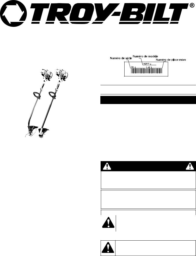
Operator’s Manual
4-Cycle Gas Trimmers
Super Bronco TB415CS/
Pony TB465SS
Before beginning, locate the unit’s model plate. It lists the model and serial numbers of your unit. Refer to the sample plate below and copy the information for future reference.
TABLE OF CONTENTS
Service Information . . . . . . . . . . . . . . . . . . . . . . . . . . . . . . . . . . . . .1 Rules for Safe Operation . . . . . . . . . . . . . . . . . . . . . . . . . . . . . . . .1 Know Your Unit . . . . . . . . . . . . . . . . . . . . . . . . . . . . . . . . . . . . . . . .3 Assembly Instructions . . . . . . . . . . . . . . . . . . . . . . . . . . . . . . . . . . .4 Oil and Fuel Information . . . . . . . . . . . . . . . . . . . . . . . . . . . . . . . . .4 Starting/Stopping Instructions . . . . . . . . . . . . . . . . . . . . . . . . . . . .5 Operating Instructions . . . . . . . . . . . . . . . . . . . . . . . . . . . . . . . . . .6 Maintenance & Repair Instructions . . . . . . . . . . . . . . . . . . . . . . . . .6 Cleaning and Storage . . . . . . . . . . . . . . . . . . . . . . . . . . . . . . . . . . .9 Troubleshooting Chart . . . . . . . . . . . . . . . . . . . . . . . . . . . . . . . . . . .9 Specifications . . . . . . . . . . . . . . . . . . . . . . . . . . . . . . . . . . . . . . . .10 Warranty Information . . . . . . . . . . . . . . . . . . . . . . . . . . . . . . . . . . .10 Parts List . . . . . . . . . . . . . . . . . . . . . . . . . . . . . . . . . . . . . . . . . . .E12
SAVE THESE INSTRUCTIONS
For service call 1-800-828-5500, or 1-800-668-1238 in Canada to obtain a list of authorized service dealers near you. For more details about your unit, visit our website at www.troy-bilt.com.
If you have difficulty assembling this product or have any questions regarding the controls, operation or maintenance of this unit, please call the Customer Support Department.
DO NOT RETURN THE UNIT TO THE RETAILER. PROOF OF PURCHASE WILL BE REQUIRED FOR WARRANTY SERVICE.
THIS PRODUCT IS COVERED BY ONE OR MORE U.S. PATENTS. OTHER PATENTS PENDING.
Service on this unit both within and after the warranty period should be performed only by an authorized and approved service dealer.
All information, illustrations, and specifications in this manual are based on the latest product information available at the time of printing. We reserve the right to make changes at any time without notice.
Copyright© 2007 MTD SOUTHWEST INC, All Rights Reserved.
Copy the model and parent part number here:
Copy the serial number here:
RULES FOR SAFE OPERATION
SPARK ARRESTOR NOTE
NOTE: For users on U.S. Forest Land and in the states of California, Maine, Oregon and Washington. All U.S. Forest Land and the state of California (Public Resources Codes 4442 and 4443), Oregon and Washington require, by law that certain internal combustion engines operated on forest brush and/or grass-covered areas be equipped with a spark arrestor, maintained in effective working order, or the engine be constructed, equipped and maintained for the prevention of fire. Check with your state or local authorities for regulations pertaining to these requirements. Failure to follow these requirements could subject you to liability or a fine. This unit is factory equipped with a spark arrestor. If it requires replacement, ask your LOCAL SERVICE DEALER to install the
Accessory Part #791-180890 Spark Arrestor Kit.
CALIFORNIA PROPOSITION 65 WARNING
WARNING
THE ENGINE EXHAUST FROM THIS PRODUCT CONTAINS CHEMICALS KNOWN TO THE STATE OF CALIFORNIA TO CAUSE CANCER, BIRTH DEFECTS OR OTHER REPRODUCTIVE HARM.
The purpose of safety symbols is to attract your attention to possible dangers. The safety symbols, and their explanations, deserve your careful attention and understanding. The safety warnings do not by themselves eliminate any danger. The instructions or warnings they give are not substitutes for proper accident prevention measures.
SYMBOL MEANING
SAFETY ALERT: Indicates danger, warning or caution. Attention is required in order to avoid serious personal injury. May be used in conjunction with other symbols or pictographs.
NOTE: Advises you of information or instructions vital to the operation or maintenance of the equipment.
DANGER: Failure to obey a safety warning will result in serious injury to yourself or to others. Always follow the safety precautions to reduce the risk of fire, electric shock and personal injury.
PART NO. 769-02774A |
(5/07) |
RULES FOR SAFE OPERATION
SYMBOL MEANING
WARNING: Failure to obey a safety warning can result in injury to yourself and others. Always follow the safety precautions to reduce the risk of fire, electric shock and personal injury.
CAUTION: Failure to obey a safety warning may result in property damage or personal injury to yourself or to others. Always follow the safety precautions to reduce the risk of fire, electric shock and personal injury.
Read the Operator’s Manual and follow all warnings and safety instructions. Failure to do so can result in serious injury to the operator and/or bystanders.
FOR QUESTIONS, CALL 1-800-345-8746 IN U.S. OR 1-800-668-1238 in CANADA
• IMPORTANT SAFETY INSTRUCTIONS •
READ ALL INSTRUCTIONS BEFORE OPERATING
WARNING: When using the unit, you must follow the safety rules. Please read these instructions before operating the unit in order to ensure the safety of the operator and any bystanders. Please keep these instructions for later use.
•Read the instructions carefully. Be familiar with the controls and proper use of the unit.
•Do not operate this unit when tired, ill, or under the influence of alcohol, drugs, or medication.
•Children and teens under the age of 15 must not use the unit, except for teens guided by an adult.
•All guards and safety attachments must be installed properly before operating the unit.
•Inspect the unit before use. Replace damaged parts. Check for fuel leaks. Make sure all fasteners are in place and secure. Replace parts that are cracked, chipped, or damaged in any way. Do not operate the unit with loose or damaged parts.
•Carefully inspect the area before starting the unit. Remove all debris and hard or sharp objects such as glass, wire, etc.
•Be aware of the risk of injury to the head, hands and feet.
•Clear the area of children, bystanders, and pets. At a minimum, keep all children, bystanders, and pets outside a 50 feet (15 m.) radius; there still may be a risk to bystanders from thrown objects. Bystanders should be encouraged to wear eye protection. If you are approached, stop the unit immediately.
•Use only 0.105 inch, 2.667 mm diameter original equipment manufacturer replacement line. Never use metal-reinforced line, wire or rope. These can break off and become dangerous projectiles.
•Squeeze the throttle control and check that it returns automatically to the idle position. Make all adjustments or repairs before using unit.
SAFETY WARNINGS FOR GAS UNITS
WARNING: Gasoline is highly flammable, and its vapors can explode if ignited. Take the following precautions:
•Store fuel only in containers specifically designed and approved for the storage of such materials.
•Avoid creating a source of ignition for spilled fuel. Do not start the engine until fuel vapors dissipate.
•Always stop the engine and allow it to cool before filling the fuel tank. Never remove the fuel tank cap or add fuel when the engine is hot. Never operate the unit without the fuel cap securely in place. Loosen the fuel tank cap slowly to relieve any pressure in the tank.
•Add fuel in a clean, well-ventilated outdoor area where there are no sparks or flames. Remove the fuel cap slowly, and only after the engine stops. Do not smoke while fueling. Wipe up any spilled fuel from the unit immediately.
•Avoid creating a source of ignition for spilled fuel. Do not start the engine until fuel vapors dissipate.
•Move the unit at least 30 feet (9.1 m) from the fueling source and site before starting the engine. Do not smoke. Keep sparks and open flames away from the area while adding fuel or operating the unit.
WHILE OPERATING
•Never start or run the unit inside a closed room or building. Breathing exhaust fumes can be fatal. Operate this unit only in a well-ventilated outdoor area.
•Wear safety glasses or goggles that meet ANSI Z87.1 standards and are marked as such. Wear ear/hearing protection when operating this unit. Wear a face or dust mask if the operation is dusty.
•Wear heavy long pants, boots, gloves and a long sleeve shirt. Do not wear loose clothing, jewelry, short pants, sandals or go barefoot. Secure hair above shoulder level.
•The cutting attachment shield must always be in place while operating the unit as a trimmer. Do not operate unit without both trimming lines extended, and the proper line installed. Do not extend the trimming line beyond the length of the shield.
•This unit does not have a clutch. The cutting attachment continues rotating when the engine is idling. If it does not, have the unit adjusted by an authorized service technician.
•Adjust the handle to your size in order to provide the best grip.
•Be sure the cutting attachment is not in contact with anything before starting the unit.
•Use the unit only in daylight or good artificial light.
•Avoid accidental starting. Be in the starting position whenever pulling the starter rope. The operator and unit must be in a stable position while starting. Refer to Starting/Stopping Instructions.
•Use the right tool. Only use this tool for its intended purpose.
•Do not overreach. Always keep proper footing and balance.
•Always hold the unit with both hands when operating. Keep a firm grip on both handles or grips.
•Keep hands, face, and feet at a distance from all moving parts. Do not touch or try to stop the cutting attachment when it rotates.
•Do not touch the engine, gear housing or muffler. These parts get extremely hot from operation, even after the unit is turned off.
•Do not operate the engine faster than the speed needed to cut, trim or edge. Do not run the engine at high speed when not cutting.
•Always stop the engine when cutting is delayed or when walking from one cutting location to another.
•If you strike or become entangled with a foreign object, stop the engine immediately and check for damage. Do not operate before repairing damage. Do not operate the unit with loose or damaged parts.
•Stop the unit, switch the engine to off, and disconnect the spark plug for maintenance or repair.
•Use only original equipment manufacturer replacement parts and accessories for this unit. These are available from your authorized service dealer. Use of any unauthorized parts or accessories could lead to serious injury to the user, or damage to the unit, and void your warranty.
•Keep unit clean of vegetation and other materials. They may become lodged between the cutting attachment and shield.
•To reduce fire hazard, replace a faulty muffler and spark arrestor. Keep the engine and muffler free from grass, leaves, excessive grease or carbon build up.
OTHER SAFETY WARNINGS
•Never store a fueled unit inside a building where fumes may reach an open flame or spark.
•Allow the engine to cool before storing or transporting. Be sure to secure the unit while transporting.
•Store the unit in a dry area, locked up or up high to prevent unauthorized use or damage, out of the reach of children.
•Never douse or squirt the unit with water or any other liquid. Keep handles dry, clean and free from debris. Clean after each use, see Cleaning and Storage instructions.
•Keep these instructions. Refer to them often and use them to instruct other users. If you loan someone this unit, also loan them these instructions.
SAVE THESE INSTRUCTIONS
2
RULES FOR SAFE OPERATION
This operator's manual describes safety and international symbols and pictographs that may appear on this product. Read the operator's manual for complete safety, assembly, operating and maintenance and repair information.
SYMBOL MEANING |
|
SYMBOL MEANING |
|||||||||
|
|
|
|
|
|
|
|
|
|
|
|
|
|
|
• SAFETY ALERT SYMBOL |
|
|
|
|
|
|
|
• THROWN OBJECTS AND ROTATING CUTTER CAN |
|
|
|
Indicates danger, warning or caution. May be used in |
|
|
|
|
|
|
|
CAUSE SEVERE INJURY |
|
|
|
conjunction with other symbols or pictographs. |
|
|
|
|
|
|
|
WARNING: Small objects can be propelled at high |
|
|
|
|
|
|
|
|
|
|
|
speed, causing injury. Keep away from the rotating rotor. |
|
|
|
|
|
|
|
|
|
|
|
|
|
|
|
• WARNING - READ OPERATOR'S MANUAL |
|
|
|
|
|
|
|
|
|
|
|
|
|
|
|
|
|
|
|
|
|
|
|
Read the operator’s manual(s) and follow all warnings |
|
|
|
|
|
|
|
• KEEP BYSTANDERS AWAY |
|
|
|
and safety instructions. Failure to do so can result in |
|
|
|
|
|
|
|
WARNING: Keep all bystanders, especially children |
|
|
|
serious injury to the operator and/or bystanders. |
|
|
|
|
|
|
|
and pets, at least 50 feet (15 m.) from the operating area. |
|
|
|
|
|
|
|
|
|
|
|
|
|
|
|
|
|
|
|
|
|
|
|
|
|
|
|
• WEAR EYE AND HEARING PROTECTION |
|
|
|
|
|
|
|
|
|
|
|
WARNING: Thrown objects and loud noise can |
|
|
|
|
|
|
|
|
|
|
|
|
|
|
|
|
|
|
• HOT SURFACE WARNING |
|
|
|
|
cause severe eye injury and hearing loss. Wear eye |
|
|
|
|
|
|
|
Do not touch a hot muffler or cylinder. You may get |
|
|
|
protection meeting ANSI Z87.1-1989 standards and |
|
|
|
|
|
|
|
burned. These parts get extremely hot from operation. |
|
|
|
ear protection when operating this unit. Use a full face |
|
|
|
|
|
|
|
When turned off they remain hot for a short time. |
|
|
|
shield when needed. |
|
|
|
|
|
|
|
|
|
|
|
|
|
|
|
|
|
|
|
|
|
|
|
|
|
|
|
|
|
|
|
|
|
|
|
• UNLEADED FUEL |
|
|
|
|
|
|
|
|
|
|
|
|
|
|
|
|
|
|
|
|
|
|
|
Always use clean, fresh unleaded fuel |
|
|
|
|
|
|
|
• OIL |
|
|
|
|
|
|
|
|
|
|
Refer to operator’s manual for the proper type of oil. |
|
|
|
|
|
|
|
|
|
|
|
|
|
|
|
|
|
|
|
|
|
|
|
|
|
|
|
|
|
|
|
|
|
|
|
|
|
|
|
|
• ON/OFF STOP CONTROL |
|
|
|
|
|
|
|
• CHOKE CONTROL |
|
|
|
|
|
|
|
|
|
|
||
|
|
|
ON / START / RUN |
|
|
|
|
|
|
|
1. • FULL choke position |
|
|
|
|
|
|
|
|
|
|
||
|
|
|
|
|
|
|
|
|
|
|
2. • PARTIAL choke position |
|
|
|
|
|
|
|
|
|
|
|
3. • RUN choke position |
|
|
|
|
|
|
|
|
|
|
|
|
|
|
|
• ON/OFF STOP CONTROL |
|
|
|
|
|
|
|
|
|
|
|
|
|
|
|
|
|
|
|
|
|
|
|
OFF or STOP |
|
|
|
|
|
|
|
• SHARP BLADE |
|
|
|
|
|
|
|
|
|
|
|
WARNING: Sharp blade on cutting attachment |
|
|
|
|
|
|
|
|
|
|
|
shield. To prevent serious injury, do not touch the line |
|
|
|
|
|
|
|
|
|
|
|
|
|
|
|
|
|
|
|
|
|
|
|
cutting blade. |
|
|
|
|
|
|
|
|
|
|
|
|
APPLICATIONS
As a trimmer:
•Cutting grass and light weeds
•Edging
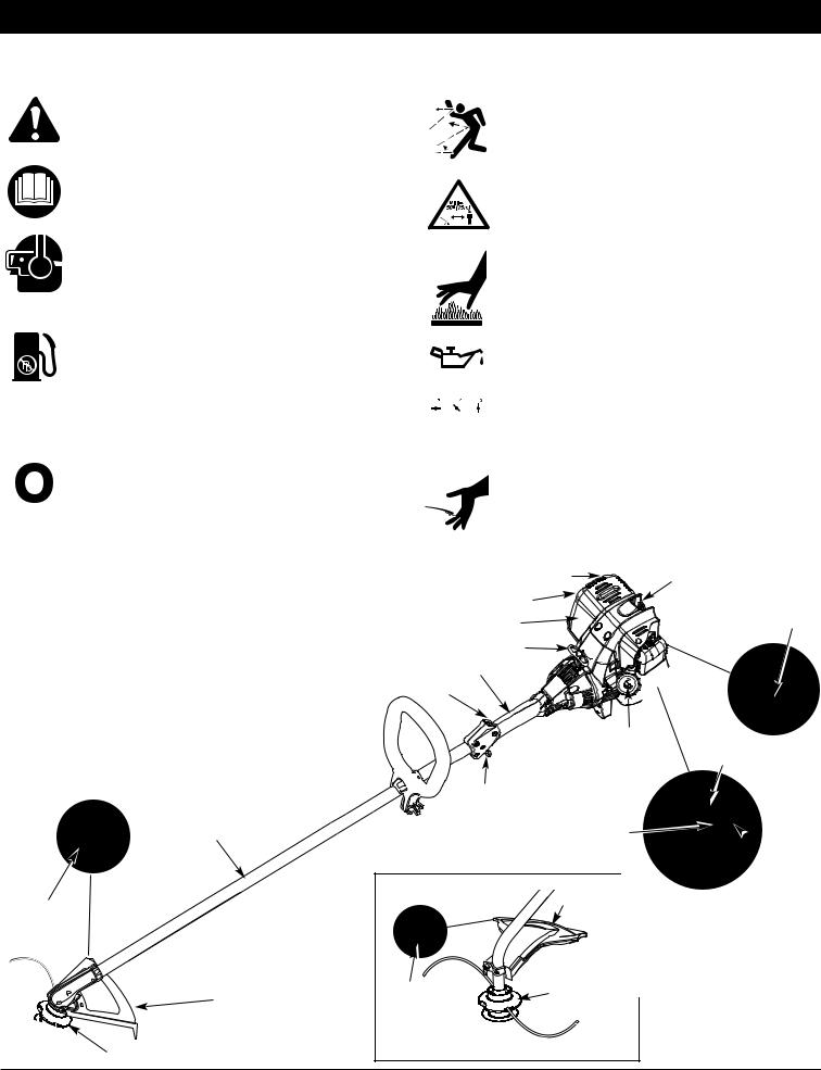
•Decorative trimming around trees, fences, etc. NOTE: The below illustration may differ slightly from your unit. For example, the picture shows a
straight shaft. Your unit may have a curved shaft.
Shaft
Housing
TB465SS |
Spark Arrestor |
Spark Plug |
|
Muffler |
Oil Fill |
|
Plug/ |
|
|
|
|
|
Muffler Guard |
Dipstick |
Starter Rope Grip
Shaft Grip
On/Off Stop Control
D-Handle 
Fuel Cap |
Choke |
|
Lever |
Throttle
Control
Air Filter Cover
 Primer
Bulb
TB415CS |
Cutting |
|
Line
Cutting
Blade
Cutting Attachment |
Cutting |
Attachment |
|
Shield |
|
Cutting Attachment |
|
3
ASSEMBLY INSTRUCTIONS
INSTALL CUTTING ATTACHMENT SHIELD
WARNING: To prevent serious personal injury, never operate the trimmer without the cutting attachment shield in place.
Use the following instructions if the cutting attachment shield on your unit is not installed. Use only the instructions that apply to the type of shaft and shield that your unit is equipped with.
TB415CS
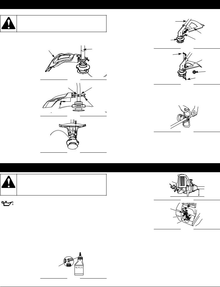
1.Place the cutting attachment shield onto the shaft housing. Be sure the guard mounting bracket slides into the slot on the edge of the cutting shield. Rotate the shield into place, counterclockwise. The holes in the guard mounting bracket and cutting attachment shield will line up (Fig. 1).
2.From inside the cutting attachment shield, push the square bolt through the hole until the threaded end protrudes through the guard mounting bracket (Fig. 2).
Cutting Attachment
Shield
Fig. 1
Guard Mounting
Bracket
Square Bolt
3. Put the washer on the bolt, then screw
the wing nut onto the bolt and tighten.
Figure 3 shows the
installation process from underneath the unit.
Shaft
Housing
 Guard
Guard
Mounting
Bracket
Washer
Wing Nut
Square Bolt
TB465SS
1.Slide the cutting attachment shield into the shield mount on the
cutting attachment. Align the screw holes in the shield with the holes in the cutting attachment (Fig. 4).
2.Place a hex lock nut into one of the three recessed holes on the top of the cutting attachment shield (Fig 5).
3.Install a screw into the hole from the bottom of the cutting attachment shield and screw it into the nut installed in step 2 (Fig. 5). Do not tighten.
Cutting |
Shield |
Attachment |
Mount |
|
Fig. 4 |
Nuts (3) |
Recessed |
|
Holes |
|
Hex Lock |
|
Nut |
|
Screws (3) |
|
Fig. 5 |
4.Repeat steps 2 and
3 until all three screws have been started, then tighten securely.
ADJUSTING THE D-HANDLE
1.Locate the wing nut on the D-Handle. Loosen the wing nut enough to loosen the
D-Handle (Fig. 6).
NOTE: Do not remove wing nut, washer, or bolt.
2.Rotate the D-Handle
to the upright |
|
position on the front |
Fig. 6 |
side of the shaft |
|
housing (Fig. 6).
NOTE: The D-handle should slant towards the powerhead of the unit.
3.Hold the unit in the operating position (Fig. 15). If necessary, reposition the D-handle to the location that provides the best grip.
4.Tighten the wing nut until the D-Handle is secure.
OIL AND FUEL INFORMATION
WARNING: OVERFILLING OIL CRANKCASE MAY CAUSE SERIOUS PERSONAL INJURY. Check and maintain the proper oil level in the crank case; it is important and cannot be overemphasized. Check the oil before each use and change it as needed. See Changing the Oil.
RECOMMENDED OIL TYPE
Using the proper type and weight of oil in the crankcase is extremely important. Check the oil before each use and change
the oil regularly. Failure to use the correct oil, or using dirty oil, can cause premature engine wear and failure. Use a high-quality SAE 30 weight oil of API (American Petroleum Institute) service class SF, SG, SH.
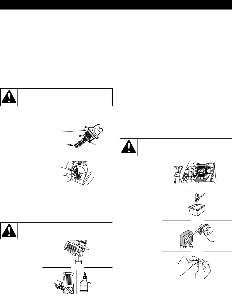
ADDING OIL TO CRANKCASE: INITIAL USE
NOTE: This unit is shipped without oil. In order to avoid damage to the unit, put oil in the crankcase before you attempt to start the unit.
Your unit is supplied with one 3.04 fluid oz. (90 ml) bottle of SAE 30 SF, SG, SH oil (Fig. 7).
NOTE: Save the bottle of oil. It can be used to measure the correct amount during future oil changes. See Changing the Oil.
1. Unscrew the top of |
|
the bottle of oil and |
|
remove the paper |
|
seal covering the |
Funnel |
opening. Replace the |
Spout |
top. Next, cut the tip |
|
off the funnel spout |
Fig. 7 |
(Fig. 7). |
2.Place the unit on a flat level surface (Fig. 8).
3.Remove the oil plug / dipstick from the crankcase (Fig. 9).
4.Pour the entire bottle of oil into the oil fill hole (Fig. 9).
NOTE: Never add oil to the fuel or fuel tank.
5.Wipe up any oil that may have spilled and reinstall the oil fill plug / dipstick.
Check oil before each use and change as needed. Refer to Changing the Oil.
Oil Fill
Fig. 8
O-Ring
Oil Fill
Plug/Dipstick
Oil Fill Hole
Fig. 9
RECOMMENDED FUEL TYPE
Old fuel is the primary reason for improper unit performance. Be sure to use fresh, clean, unleaded gasoline.
NOTE: This is a four cycle engine. In order to avoid damage to the unit, do not mix oil with gasoline.
Definition of Blended Fuels
Today's fuels are often a blend of gasoline and oxygenates such as ethanol, methanol or MTBE (ether). Alcohol-blended fuel absorbs water. As little as 1% water in the fuel can make fuel and oil separate or form acids when stored. Use fresh fuel (less than 60 days old), when using alcohol-blended fuel.
4
OIL AND FUEL INFORMATION
Using Blended Fuels
If you choose to use a blended fuel, or its use is unavoidable, follow recommended precautions:
•Always use fresh unleaded gasoline
•Use the fuel additive STA-BIL® or an equivalent
•Drain tank and run the engine dry before storing unit
Using Fuel Additives
The use of fuel additives, such as STA-BIL® Gas Stabilizer or an equivalent, will inhibit corrosion and minimize the formation of gum deposits. Using a fuel additive can keep fuel from forming harmful deposits in the carburetor for up to six (6) months. Add 0.8 oz. (23 ml.) of fuel additive per gallon of fuel according to the instructions on the container. NEVER add fuel additives directly to the unit's gas tank.
WARNING: Add fuel in a clean, well ventilated outdoor area. Wipe up any spilled fuel immediately. Avoid creating a source of ignition for spilt fuel. Do not start the engine until fuel vapors dissipate.
FUELING THE UNIT
WARNING: Gasoline is extremely flammable. Ignited vapors may explode. Always stop the engine and allow it to cool before filling the fuel tank. Do not smoke while filling the tank. Keep sparks and open flames at a distance from the area.
1.Remove the fuel cap (Fig. 10).
2.Place the gas container’s spout into the fill hole on the fuel tank (Fig. 10) and fill the tank.
NOTE: Do not overfill the tank.
Gas Can
Spout
Fuel Cap |
Fuel Tank |
Fig. 10
WARNING: Gasoline is extremely flammable. Ignited vapors may explode. Always stop the engine and allow it to cool before filling the fuel tank. Do not smoke while filling the tank. Keep sparks and open flames at a distance from the area.
3.Wipe up any gasoline that may have spilled.
4.Reinstall the fuel cap.
5.Move the unit at least 30 ft. (9.1 m) from the fueling source and site before starting the engine.
NOTE: Dispose of the old gasoline in accordance to Federal, State and Local regulations.
STARTING AND STOPPING INSTRUCTIONS
WARNING: Operate this unit only in a well-ventilated outdoor area. Carbon monoxide exhaust fumes can be lethal in a confined area.
WARNING: Avoid accidental starting. Make sure you are in the starting position when pulling the starter rope (Fig. 13). To avoid serious injury, the operator and unit must be
in a stable position while starting.
Make sure that any Add-On item is installed correctly and secure before starting the unit.
STARTING INSTRUCTIONS
1.Check the oil level in the crankcase. Refer to Checking the Oil Level.
2.Fill the fuel tank with fresh, clean unleaded gasoline. Refer to Fueling the Unit.
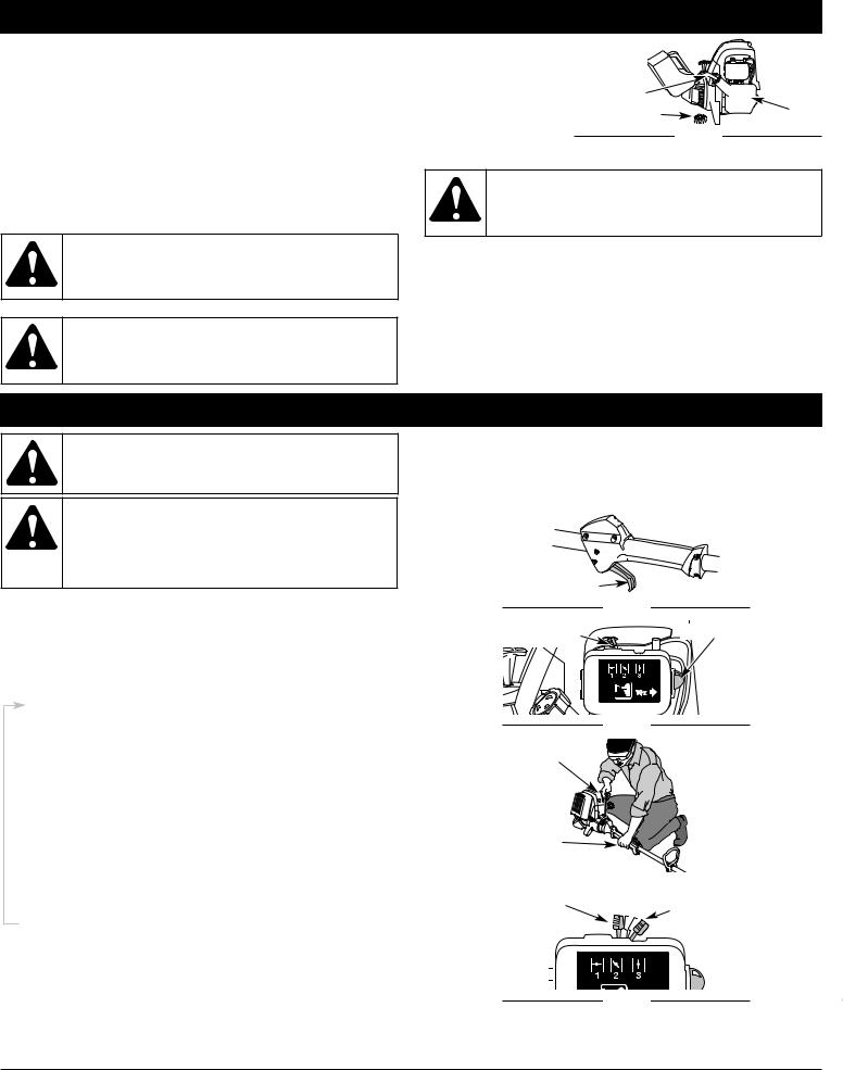
3.Make sure the On/Off Stop Control in the ON ( I ) position (Fig. 11).
4. Fully press and release the primer bulb 10 times, slowly. Some amount of fuel should be visible in the primer bulb and fuel lines (Fig. 12). If you can’t see fuel in the bulb, press and release the bulb as many times as it takes before you can see fuel in it.
5.Place the choke lever in Position 1 (Fig. 12).
6.Crouch in the starting position (Fig. 13), squeeze the throttle control, and pull the starter rope briskly 5 times.
7.Place the choke lever in Position 2 (Fig. 14).
8.While squeezing the throttle control, pull the starter rope briskly 1 to 4 times to start the engine.
9.Keep the throttle squeezed and allow the engine to warm up for 15 to 30 seconds.
10.Place the choke lever in Position 3 (Fig. 14). The unit is ready for use.
IF... the engine does not start, go back to step 4.
IF... the engine fails to start after a few attempts, place the choke lever in Position 3 and squeeze the throttle control. Pull the starter rope briskly 3 to 8 times. The engine should start. If not, repeat.
IF WARM... If the engine is already warm, make sure the On/Off Stop control is in the ON position and start the unit with the choke lever in Position 2. After the unit starts, move the choke lever to Position 3.
STOPPING INSTRUCTIONS
1.Release your hand from the throttle control. Allow the engine to cool down by idling.
2.Put the On/Off Stop Control in the OFF (O) position.
Stop/ Off (O) 

 Start/ On (I)
Throttle Control |
|
|
Fig. 11 |
Choke Lever |
Primer Bulb |
Postition 1 |
|
Fig. 12
Starter Rope
Throttle
Control
|
|
|
|
Fig. 13 |
|
||
Position 2 |
Position 3 |
||||||
|
|
||||||
|
|
||||||
|
|
|
|
|
|
||
|
|
|
|
|
|
|
|
|
|
|
|
|
|
|
|
|
|
|
|
|
|
|
|
|
|
|
|
|
|
|
|
|
|
|
|
|
|
|
|
|
|
|
|
|
|
|
|
Fig. 14
5
OPERATING INSTRUCTIONS
WARNING: Always wear eye, hearing, foot and body protection to reduce the risk of injury when operating this unit.
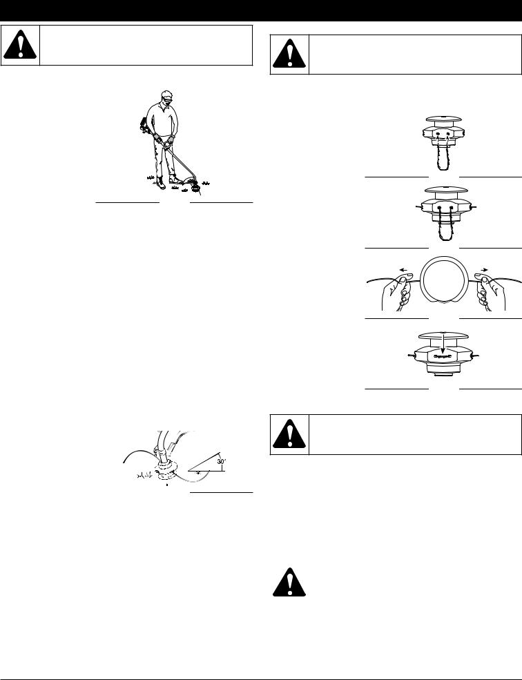
HOLDING THE TRIMMER
FIXED LINE INSTALLATION
WARNING: Never use metal-reinforced line, wire, chain, or rope. These can break off and become dangerous projectiles.
Before operating the unit, stand in the operating position (Fig. 15). Check for the following: 
• The operator is wearing eye protection and
proper clothing
• With a slightly-bent right arm, the operator’s right hand is holding the shaft grip
• The operator’s left arm is straight, the left hand holding the handle
• |
The unit is at waist level |
|
• |
The cutting attachment |
Fig. 15 |
|
is parallel to the ground |
|
|
and easily contacts the grass without the need to bend over |
|
TIPS FOR BEST TRIMMING RESULTS
•For best trimming results, operate unit at full throttle.
•Keep the cutting attachment parallel to the ground.
•Do not force the cutting attachment. Allow the tip of the line to do the cutting, especially along walls. Cutting with more than the tip will reduce cutting efficiency and may overload the engine.
•Cut grass over 8 inches (200 mm) by working from top to bottom in small increments to avoid premature line wear or engine drag.
•Cut from right to left.
•Slowly move the trimmer into and out of the cutting area at the desired height. Move either in a forward-backward or side-to-side motion. Cutting shorter lengths produces the best results.
•Trim only when grass and weeds are dry.
•The life of your cutting line is dependent upon:
-Proper adherence of explained trimming techniques
-What vegetation is cut
-Where vegetation is cut
For example, the line will wear faster when trimming against a foundation wall as opposed to trimming around a tree. It is normal for some line breakage to occur from regular use.
DECORATIVE TRIMMING
Decorative trimming is accomplished by removing all vegetation around trees, posts, fences and more. Rotate the whole unit so that the cutting attachment is at a 30° angle to the
ground (Fig. 16). |
|
Fig. 16 |
|
||
|
|
Always use original equipment manufacturer 0.105 inch (2.667 mm) replacement line. Lines other than those specified may make the engine overheat or fail.
To install the trimming line:
1. Insert each end of the replacement line into
the holes on either side of retention hook (Fig. 17).
2. Push the ends
through until they
Fig. 17
stick out of the sides of the head (Fig. 18).
3.Pull the ends
through making sure |
|
|
that the ends are of |
|
|
equal length and the |
|
|
middle of the line is |
|
|
centered between |
Fig. 18 |
|
the insertion holes |
||
|
||
(Fig. 19). |
|
|
4. If the ends are not of |
|
|
equal length, push |
|
|
the longer end back |
|
|
through the head |
|
|
part way and pull the |
|
|
shorter end to |
Fig. 19 |
|
compensate. Repeat |
||
|
||
until both ends are |
|
|
the same length. |
|
5. Push the trimmer line until it lies flat
against the cutting head (Fig. 20).
Make sure the two Fig. 20 lengths of cutting
line are of equal length. If they are not, adjust until they are.
WARNING: Always use the correct line length when installing trimming line on the unit. If the two lengths of cutting line are not of equal length, the unit may develop a vibration.
MAINTENANCE AND REPAIR INSTRUCTIONS |
|||
|
|
|
|
MAINTENANCE SCHEDULE |
NOTE: Maintenance, replacement, or repair of the emission control |
||
Perform these required maintenance procedures at the frequency stated in |
devices and system may be performed by any non-road engine |
||
repair establishment, individual or authorized service dealer. |
|||
the table. These procedures should also be a part of any seasonal tune-up. |
|||
|
|
||
NOTE: Some maintenance procedures may require special tools or |
|
WARNING: To prevent serious injury, never perform |
|
skills. If you are unsure about these procedures take your |
|
maintenance or repairs with unit running. Always service |
|
unit to any non-road engine repair establishment, individual |
|
and repair a cool unit. Disconnect the spark plug wire to |
|
or authorized service dealer. |
|
ensure that the unit cannot start. |
|
|
|
|
|
6
MAINTENANCE AND REPAIR INSTRUCTIONS
FREQUENCY |
MAINTENANCE REQUIRED |
SEE |
|
|
|
|
|
Before starting engine |
Fill fuel tank with fresh fuel |
Page 4 |
|
Check Oil |
Page 7 |
||
|
|||
|
|
|
|
Every 10 hours |
Clean and re-oil air filter |
Page 7 |
|
|
|
|
|
First change at 10 hours |
Change Oil |
Page 7 |
|
Every 25 hours |
Change Oil |
Page 7 |
|
Every 25 hours thereafter |
Clean spark arrestor |
Page 9 |
|
|
|
|
|
10 hours on new engine |
Check rocker arm to valve clearance and adjust |
Page 8 |
|
Every 25 hours |
Check rocker arm to valve clearance and adjust |
Page 8 |
|
Every 25 hours |
Check spark plug condition and gap |
Page 9 |
|
|
|
|
CHECKING THE OIL LEVEL
The importance of checking and maintaining the proper oil level in the crankcase cannot be overemphasized. Check oil before each use:
1.Stop the engine and allow oil to drain into the crankcase.
CAUTION: To prevent extensive engine wear and damage to the unit, always maintain the proper oil level in the crankcase. Never operate the unit with the oil level below the bottom of the dipstick.
2.Place the unit on a flat, level surface to get a proper oil level reading.
3.Keep dirt, grass clippings and other debris out of the engine. Clean the area around the oil fill plug/dipstick before removing it.
4.Remove the oil fill Oil Fill Plug/Dipstick 
plug/dipstick and wipe off oil. Reinsert it all the way back in.
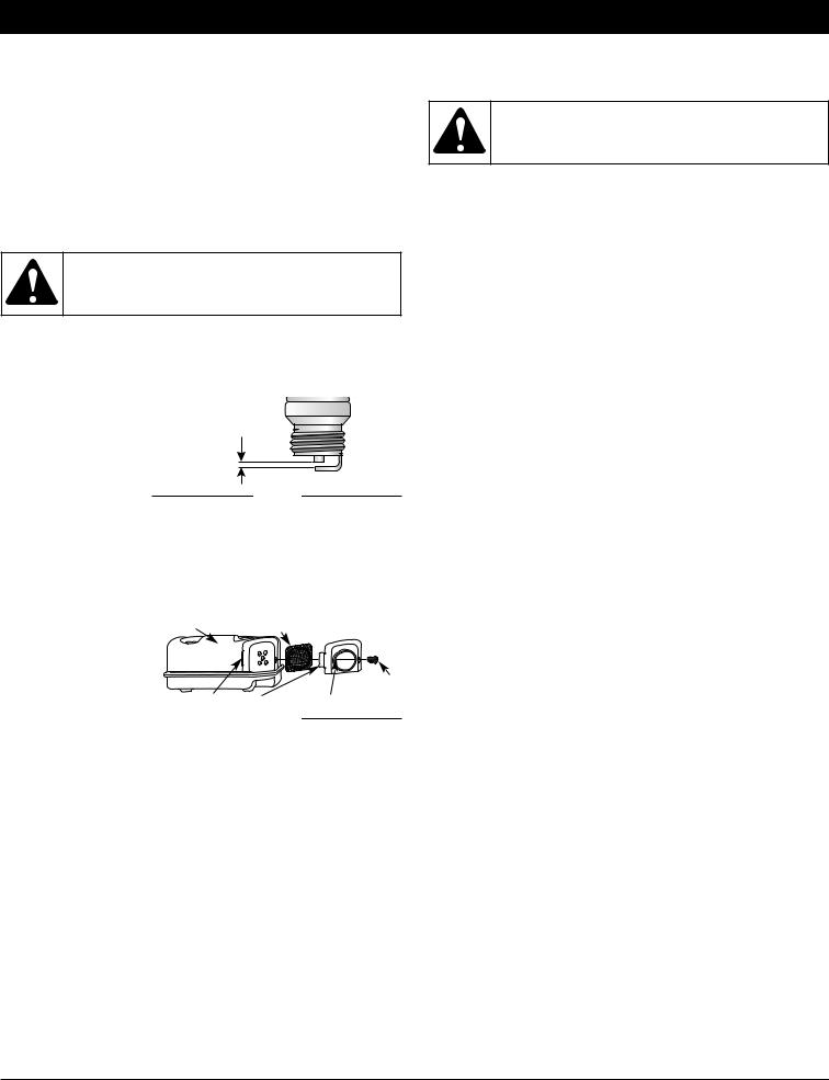
5. Remove the oil fill |
Add 1.4-1.5 Oz. |
|
plug/dipstick and |
(41-44 ml) |
Top of Dipstick |
check the oil level. |
|
Fig. 21 |
Oil should be up to |
|
|
|
|
|
the top of the dipstick (Fig. 21). |
|
|
6. If the level is low, |
|
|
add a small amount |
O-Ring |
|
of oil to the oil fill |
|
|
hole and recheck |
Oil Fill |
|
(Fig. 22). Repeat this Plug/Dipstick |
|
|
procedure until the |
Oil Fill Hole |
|
oil level reaches the |
|
Fig. 22 |
top of the dipstick. |
|
|
NOTE: Do not overfill the unit.
NOTE: Make sure the O-ring is in place on the oil fill plug/dipstick when checking and changing the oil (Fig. 22).
CHANGING THE OIL
For a new engine, change the oil after the first 10 hours of operation. Change the oil while the engine is still warm. The oil will flow freely and carry away more impurities.
CAUTION: Wear gloves to prevent injury when handling the unit.
1.Unplug spark plug boot to prevent accidental starting.
2.Remove the oil fill plug/dipstick.
3.Pour the oil out of the oil fill hole and into a container by tipping the unit to a vertical position (Fig. 23). Allow ample time for complete drainage.
4.Wipe up any oil residue on the unit
Fig. 23
Fill Level
Fig. 24
and clean up any oil that may have spilled. Dispose of the oil according to Federal, State and local regulations.
5.Refill the crankcase with 3.04 fluid ounce (90 ml) of SAE 30 SF, SG, SH oil.
NOTE: Use the bottle and spout saved from initial use to measure the correct amount of oil. The top of the label on the bottle measures approximately 3.04 ounces (90 ml) (Fig. 24).
Check the level with the dipstick. If the level is low, add a small amount of oil and recheck. Do not overfill (Fig. 24).
6.Replace the oil fill plug/dipstick.
7.Reconnect the spark plug boot.
AIR FILTER MAINTENANCE Cleaning the Air Filter
Clean and re-oil the air filter every 10 hours of operation. It is an important item to maintain. Failure to maintain your air filter properly can result in poor performance or can cause permanent damage to your engine.
WARNING: To avoid serious personal injury, always turn the unit off and allow it to cool before you clean or service it.
1.Open the air filter cover. Push the tab on the right side of the
cover inward. Then Air Filter Cover pull the air filter  cover out and to the
left (Fig. 25).
NOTE: It may be |
|
|
necessary to |
Tab |
|
remove the fuel |
Fig. 25 |
|
cap to completely |
||
|
||
remove the air |
|
|
filter cover. |
|
2. Remove the air filter (Fig. 25).
3. Wash the filter in
|
detergent and water |
|
|
(Fig. 26). Rinse the |
Fig. 26 |
|
filter thoroughly and |
|
|
|
|
|
allow it to dry. |
|
4. |
Apply enough clean |
|
|
SAE 30 motor oil to |
|
|
lightly coat the filter |
|
|
(Fig. 27). |
|
5. |
Squeeze the filter to |
|
|
spread and remove |
Fig. 27 |
|
excess oil (Fig. 28). |
|
6. |
Replace the filter |
|
|
(Fig. 29). |
|
NOTE: If the unit is
operated without |
|
|
the air filter, you |
|
|
will VOID the |
Fig. 28 |
|
warranty. |
||
|
7.Reinstall the air filter cover. Position the hooks on the left side of the air filter cover into the slots at the left side of the back plate (Fig. 30).
7

MAINTENANCE AND REPAIR INSTRUCTIONS
NOTE: It may be necessary to remove the fuel cap to reinstall the air filter cover.
8.Swing the cover to
the right until the tab |
Fig. 29 |
on the air filter cover Air Filter Cover |
|
snaps into place in |
|
the slot on the back |
|
plate (Fig. 30). |
Air Filter |
9. Replace the fuel cap |
|
if it was removed. |
Tab |
|
CARBURETOR |
Fig. 30 |
ADJUSTMENT |
WARNING: The cutting attachment may spin during idle speed adjustments. Wear protective clothing and observe all safety instructions to prevent serious personal injury.
The idle speed of the engine is adjustable. An idle adjustment screw is reached though a hole
in the top of the engine
cover (Fig. 31).
NOTE: Careless adjustments can seriously
damage your unit. An
authorized
service dealer should make carburetor adjustments.
Check Fuel
Old fuel is usually the reason for improper unit performance. Drain and refill the tank with fresh fuel prior to making any adjustments. Refer to Oil and Fuel Information.
Clean Air Filter
The condition of the air filter is important to the operation of the unit. A dirty air filter will restrict air flow. This is often mistaken for an out of adjustment carburetor. Check the condition of the air filter before adjusting the idle speed screw. Refer to Air Filter Maintenance.
Adjust Idle Speed Screw
If, after checking the fuel and cleaning the air filter, the engine still will not idle, adjust the idle speed screw as follows:
1.Start the engine and let it run at a high idle for a minute to warm up. Refer to Starting/Stopping Instructions.
2.Release the throttle trigger and let the engine idle. If the engine stops, insert a small phillips or flat blade screwdriver into the hole in the air filter/muffler cover (Fig. 31). Turn the idle speed screw in, clockwise, 1/8 of a turn at a time (as needed) until the engine idles smoothly.
Checking the fuel, cleaning the air filter, and adjusting the idle speed should solve most engine problems. If not and all of the following are true:
•the engine will not idle
•the engine hesitates or stalls on acceleration
•there is a loss of engine power
Have the carburetor adjusted by an authorized service dealer.
ROCKER ARM CLEARANCE
WARNING: To prevent serious personal injury, make sure the cutting attachment has stopped rotating before you turn it off and set it down.
This requires disassembly of the engine. If you feel unsure or unqualified to perform this, take the unit to an authorized service center.
NOTE: Inspect the valve to rocker arm clearance with a feeler gauge after the first 10 hours of operation and then every 25 hours of operation thereafter.
•The engine must be cold when checking or adjusting the valve clearance.
•This task should be performed inside, in a clean, dust free area.
1.Remove the muffler cover by pressing down on it, separating it from the engine cover. Using a flat blade screwdriver, disengage the middle and front tabs and slots first. The cover will hinge off from the rear tab (Fig. 32).
2.Remove the two (2) screws on top of the engine cover with a Flat-head or T-25 Torx screwdriver (Fig. 33).
3.Remove the screw behind the engine cover (Fig. 34).
Engine Cover |
|
|
Rear |
Middle Tab |
Front Tab |
|
||
Slot & |
|
|
Tab |
|
|
Middle Slot |
Front Slot |
|
|
Fig. 32 |
|
|
Top View Of The Engine |
|
Engine Cover |
Remove Screws |
|
Muffler
Fig. 33
Screw
4. |
Disconnect the |
|
|
|
spark plug wire. |
Fig. 34 |
|
5. |
Clean dirt from |
||
|
|||
|
around the spark |
Rocker Arm Cover |
|
|
plug. Remove the |
Spark |
|
|
spark plug from the |
||
|
cylinder head by |
Plug |
|
|
turning a 5/8 in. |
Hole |
|
|
|
||
|
socket |
|
|
|
counterclockwise. |
|
6. |
Remove the engine |
|
Fig. 35 |
|
|
|
|
|
|||
|
cover (Fig. 33). |
Rocker Arms |
Intake |
Adjustment |
|
7. |
Clean dirt from around |
||||
|
|
Nuts |
|||
|
the rocker arm cover. |
|
|
||
|
|
|
|
||
|
Remove the screw |
|
|
Exhaust |
|
|
holding the rocker arm |
|
|
||
|
|
|
|
||
|
cover with a large flat |
Feeler Gauge |
|
||
|
blade screwdriver or |
|
|||
|
|
|
|
||
|
Torx T-25 bit (Fig. 35). |
|
Fig. 36 |
|
|
|
Remove the rocker |
|
|
|
|
|
arm cover and gasket. |
|
|
|
|
8.Pull the starter rope slowly to bring the piston to the top of its travel, (known as top dead center). Check that:
•The piston is at the top of its travel while looking in the spark
plug hole (Fig. 36) |
Exhaust |
|
|
• Both rocker arms |
Adjustment Nut |
Feeler Gauge |
|
move freely, and |
Exhaust |
|
|
both valves are |
Clearance: |
|
|
closed |
.003-.006 in. |
|
|
If these statements |
(.076-0.152 mm) |
Exhaust |
|
are not true, repeat |
Intake Clearance: |
||
Valve Stem |
|||
this step. |
.003–.006 in. |
||
|
9. Slide the feeler (.076–0.152 mm)  Intake Valve Stem
gauge between the |
|
Fig. 37 |
|
||
rocker arm and the |
|
|
|
|
|
|
|
valve return spring. Measure the clearance between the valve stem and rocker arm (Fig. 36). Measure both the intake and exhaust valves.
The recommended clearance for the intake and exhaust is .003 –
.006 in. (.076 – 0.152 mm). Use a standard automotive feeler gauge at .005 in. (0.127mm). The feeler gauge should slide between the rocker arm and valve stem with a slight amount of resistance, without binding. Figure 37 shows how to measure the clearance.
10. If the clearance is not within specification:
a. Turn the adjusting nut using a 5/16 inch (8 mm) wrench or nut driver (Fig. 36).
8
MAINTENANCE AND REPAIR INSTRUCTIONS
•To increase clearance, turn the adjusting nut counterclockwise.
•To decrease clearance, turn the adjusting nut clockwise. b. Recheck both clearances, and adjust as necessary.
11.Reinstall the rocker arm cover using a new gasket. Torque the screw to 20–30 in•lb (2.2–3.4 N•m).
12.Reinstall the engine cover. Check alignment of the cover before tightening the screws. Tighten screws.
13.Reinstall the muffler cover. Slip the rear tab on the muffler cover into the engine cover rear slot. Then slide the remaining slots into the tabs until they snap into place (Fig. 32).
14.Check the spark plug and reinstall. See Replacing the Spark Plug.
15.Replace the spark plug wire.
REPLACING THE SPARK PLUG
WARNING: To prevent serious personal injury, make sure the cutting attachment has stopped rotating before you turn it off and set it down.
3.Pull the tab on the spark arrestor cover out of the muffler. Remove the spark arrestor cover.
4.Remove the spark arrestor screen from the spark arrestor cover.
5.Clean the spark arrestor screen with a wire brush or replace it.
WARNING: To avoid serious personal injury, always turn your unit off and allow it to cool before you clean or service it.
6.Reinstall the spark arrestor screen, spark arrestor cover and screw.
CLEANING
Use a small brush to clean off the outside of the unit. Do not use strong detergents. Household cleaners that contain aromatic oils such as pine and lemon, and solvents such as kerosene, can damage plastic housing or handle. Wipe off any moisture with a soft cloth.
STORAGE
•Never store the unit with fuel in the tank where fumes may reach an open flame or spark.
Use a replacement part number 791-180852B spark plug. The correct air gap is 0.025 in. (0.635 mm.). Remove the plug after every 25 hours of operation and check its condition.
1.Stop the engine and allow it to cool. Grasp the plug wire firmly and pull the cap from the spark plug.
2. Clean dirt from |
|
around the spark |
|
plug. Remove the |
|
spark plug from the |
0.025 in. |
cylinder head by |
|
turning a 5/8 in. |
(0.635 mm.) |
socket |
Fig. 38 |
counterclockwise. |
3.Replace cracked, fouled or dirty spark plug. Set the air gap at 0.025 in. (0.635 mm.) using a feeler gauge (Fig. 38).
4.Install a correctly-gapped spark plug in the cylinder head. Turn the 5/8 in. socket clockwise until snug.
If using a torque wrench torque to: 110-120 in.•lb. (12.3-13.5 N•m) Do not over tighten.
SPARK ARRESTOR MAINTENANCE
1. |
Remove the muffler |
Muffler Spark Arrestor Screen |
|
|
cover. See Rocker |
|
|
|
Arm Clearance. |
|
|
2. |
With a flat blade |
|
Screw |
|
screwdriver or Torx T- |
|
|
|
20 bit, remove the |
Slot |
Tab Spark Arrestor Cover |
|
screw attaching the |
|
|
spark arrestor cover to |
|
Fig. 39 |
|
||
the muffler (Fig. 39). |
|
|
•Allow the engine to cool before storing.
•Lock up the unit to prevent unauthorized use or damage.
•Store the unit in a dry, well-ventilated area.
•Store the unit out of the reach of children.
LONG TERM STORAGE
1.Drain all gasoline from the gas tank into a container. Do not use gas that has been stored for more than 60 days. Dispose of the old gasoline in accordance to Federal, State, and Local regulations.
2.Start the engine and allow it to run until it stalls. This ensures that all gasoline has been drained from the carburetor.
3.Allow the engine to cool. Remove the spark plug and put 5 drops of high quality motor oil into the cylinder. Pull the starter rope slowly to distribute the oil. Reinstall the spark plug.
NOTE: Remove the spark plug and drain all of the oil from the cylinder before attempting to start the trimmer after storage.
4.Change the oil, referring to Changing the Oil. Dispose of the old oil in accordance to Federal, State and Local regulations.
5.Thoroughly clean the unit and inspect for any loose or damaged parts. Repair or replace damaged parts and tighten loose screws, nuts or bolts. The unit is ready for storage.
TRANSPORTING
•Allow the engine to cool before transporting.
•Secure the unit while transporting.
•Drain the gas tank before transporting.
•Tighten gas cap before transporting.
|
TROUBLESHOOTING |
|
|
|
|
|
|
|
ENGINE WILL NOT START |
|
|
CAUSE |
|
ACTION |
|
|
|
Empty fuel tank |
|
Fill fuel tank with fuel |
Primer bulb wasn't pressed enough |
|
Press primer bulb fully and slowly 10 times |
|
|
|
On/Off control in the STOP position |
|
Turn On/Off control to ON |
Old fuel |
|
Drain gas tank and add fresh fuel |
|
|
|
Fouled spark plug |
|
Replace or clean the spark plug |
Plugged spark arrestor |
|
Clean or replace spark arrestor |
|
|
|
ENGINE WILL NOT IDLE |
|
|
CAUSE |
|
ACTION |
|
|
|
Air filter is plugged |
|
Replace or clean the air filter |
Old fuel |
|
Drain gas tank and add fresh fuel |
|
|
|
Improper carburetor adjustment |
|
Adjust according to the Carburetor Adjustments section |
|
|
|
9

|
TROUBLESHOOTING |
|
|
|
|
|
|
|
ENGINE WILL NOT ACCELERATE |
|
|
CAUSE |
|
ACTION |
|
|
|
Old fuel |
|
Drain gas tank and add fresh fuel mixture |
Improper carburetor adjustment |
|
Take to an authorized service dealer for an adjustment |
|
|
|
Cutting attachment bound with grass |
|
Stop the engine and clean the cutting attachment |
Dirty air filter |
|
Clean or replace the air filter |
|
|
|
Plugged spark arrestor |
|
Clean or replace spark arrestor |
|
|
|
ENGINE LACKS POWER OR STALLS WHEN CUTTING |
|
|
CAUSE |
|
ACTION |
|
|
|
Old fuel |
|
Drain gas tank and add fresh fuel |
Improper carburetor adjustment |
|
Take to an authorized service dealer for an adjustment or take to a |
|
authorized service dealer |
|
|
|
|
|
|
|
Fouled spark plug |
|
Replace or clean the spark plug |
Plugged spark arrestor |
|
Clean or replace spark arrestor |
|
|
|
If further assistance is required, contact your authorized service dealer.
|
SPECIFICATIONS |
|
|
|
|
|
|
|
ENGINE* |
|
|
Engine Type . . . . . . . . |
. . . . . . . . . . . . . . . . . . . . . . . . . . . . . . . . . . . . . . . . . . . . . . . . . . . . . . . . . . . |
. . . . . . . . . . . . . . . . . . . Air-Cooled, 4-Cycle |
Displacement . . . . . . . |
. . . . . . . . . . . . . . . . . . . . . . . . . . . . . . . . . . . . . . . . . . . . . . . . . . . . . . . . . . . |
. . . . . . . . . . . . . . . . . . . 1.6 cu. in. (26.2 cc) |
Operating RPM . . . . . . |
. . . . . . . . . . . . . . . . . . . . . . . . . . . . . . . . . . . . . . . . . . . . . . . . . . . . . . . . . . . |
. . . . . . . . . . . . . . . . . . . 6,800 - 9,800 rpm |
Idle Speed RPM . . . . . |
. . . . . . . . . . . . . . . . . . . . . . . . . . . . . . . . . . . . . . . . . . . . . . . . . . . . . . . . . . . |
. . . . . . . . . . . . . . . . . . . 3,600 - 4,400 rpm |
Ignition Type . . . . . . . . . |
. . . . . . . . . . . . . . . . . . . . . . . . . . . . . . . . . . . . . . . . . . . . . . . . . . . . . . . . . . . |
. . . . . . . . . . . . . . . . . . . . . . . . . . Electronic |
Ignition Switch . . . . . . . |
. . . . . . . . . . . . . . . . . . . . . . . . . . . . . . . . . . . . . . . . . . . . . . . . . . . . . . . . . . . |
. . . . . . . . . . . . . . . . . . . . . . .Rocker Switch |
Valve clearance . . . . . . |
. . . . . . . . . . . . . . . . . . . . . . . . . . . . . . . . . . . . . . . . . . . . . . . . . . . . . . . . . . . |
. . . . . . . . . . .003–.006 in. (.076–.152 mm)) |
Spark Plug Gap . . . . . . |
. . . . . . . . . . . . . . . . . . . . . . . . . . . . . . . . . . . . . . . . . . . . . . . . . . . . . . . . . . . |
. . . . . . . . . . . . . . . 0.025 inch (0.635 mm) |
Lubrication . . . . . . . . . . |
. . . . . . . . . . . . . . . . . . . . . . . . . . . . . . . . . . . . . . . . . . . . . . . . . . . . . . . . . . . |
. . . . . . . . . . . . . . . . . . . . . . . . . SAE 30 Oil |
Crankcase Oil Capacity . . . . . . . . . . . . . . . . . . . . . . . . . . . . . . . . . . . . . . . . . . . . . . . . . . . . . . . . . . |
. . . . . . . . . . . . . . . . . . . . . . 3.04 oz (90 ml) |
|
Fuel . . . . . . . . . . . . . . . |
. . . . . . . . . . . . . . . . . . . . . . . . . . . . . . . . . . . . . . . . . . . . . . . . . . . . . . . . . . . |
. . . . . . . . . . . . . . . . . . . . . . . . . . Unleaded |
Carburetor . . . . . . . . . . |
. . . . . . . . . . . . . . . . . . . . . . . . . . . . . . . . . . . . . . . . . . . . . . . . . . . . . . . . . . . |
. . . . . . . . . . . . . . . Diaphragm, All-Position |
Starter . . . . . . . . . . . . . |
. . . . . . . . . . . . . . . . . . . . . . . . . . . . . . . . . . . . . . . . . . . . . . . . . . . . . . . . . . . |
. . . . . . . . . . . . . . . . . . . . . . . . Auto Rewind |
Muffler . . . . . . . . . . . . . |
. . . . . . . . . . . . . . . . . . . . . . . . . . . . . . . . . . . . . . . . . . . . . . . . . . . . . . . . . . . |
. . . . . . . . . . . . . . . . . . . Baffled with Guard |
Throttle . . . . . . . . . . . . . |
. . . . . . . . . . . . . . . . . . . . . . . . . . . . . . . . . . . . . . . . . . . . . . . . . . . . . . . . . . . |
. . . . . . . . . . . . . . . . Manual Spring Return |
Fuel Tank Capacity . . . |
. . . . . . . . . . . . . . . . . . . . . . . . . . . . . . . . . . . . . . . . . . . . . . . . . . . . . . . . . . . |
. . . . . . . . . . . . . . . . . . . . . . 12 oz (355 ml) |
|
|
|
DRIVE SHAFT AND CUTTING ATTACHMENT* |
|
|
Drive Shaft Housing . . . |
. . . . . . . . . . . . . . . . . . . . . . . . . . . . . . . . . . . . . . . . . . . . . . . . . . . . . . . . . . . |
. . . . . . . . . . . . . . . . . . . . . . . . . Steel Tube |
Throttle Control . . . . . . |
. . . . . . . . . . . . . . . . . . . . . . . . . . . . . . . . . . . . . . . . . . . . . . . . . . . . . . . . . . . |
. . . . . . . . . . . . . . . . . . . . Finger-Tip Trigger |
Approximate Unit Weight (No fuel, with handle, shield and cutting attachment) . . . . . . . . . . . . . . . |
. . . . . . . . . . . . . . . . . . . . . . 13.5 lbs (6 kg) |
|
Cutting Mechanism: |
TB415CS & TB465SS: . . . . . . . . . . . . . . . . . . . . . . . . . . . . . . . . . . . . . . . . . |
. . . . . . . . . . . . . Fixed String Cutting Head |
Line Spool Diameter: |
TB415CS & TB465SS: . . . . . . . . . . . . . . . . . . . . . . . . . . . . . . . . . . . . . . . . . |
. . . . . . . . . . . . . . . . . . 3 inches (76.2 mm) |
Trimming Line Diameter: |
|
|
TB415CS & TB465SS: . |
. . . . . . . . . . . . . . . . . . . . . . . . . . . . . . . . . . . . . . . . . . . . . . . . . . . . . . . . . . |
0.105 inches (2.667 mm) square cutting line |
TB415CS & TB465SS Cutting Path Diameter . . . . . . . . . . . . . . . . . . . . . . . . . . . . . . . . . . . . . . . . . |
. . . . . . . . . . . . . . . . . 16 inches (40.64 cm) |
|
California / EPA Emission Control Warranty Statement
YOUR WARRANTY RIGHTS AND OBLIGATIONS
The California Air Resources Board, the Environmental Protection Agency, and Troy-Bilt LLC ( Troy-Bilt) are pleased to explain the emission control system warranty on your 2007 and later small off-road engine. In California and the 49 states, new small off-road engines must be designed, built and equipped to meet the state’s stringent anti-smog standards. Troy-Bilt must warrant the emission control system on your small off-road engine for the periods of time listed below provided there has been no abuse, neglect or improper maintenance of your small off-road engine.
Your emission control system may include parts such as the carburetor or fuel-injection system, the ignition system, and catalytic converter. Also included may be hoses, belts, connectors and other emission-related assemblies.
Where a warrantable condition exists, Troy-Bilt will repair your small off-road engine at no cost to you including diagnosis, parts and labor. The 2007 and later small off-road engines are warranted for two years. If any emission-related part on your engine is defective, the part will be repaired or replaced by Troy-Bilt.
OWNERS WARRANTY RESPONSIBILITIES
As the small off-road engine owner, you are responsible for the performance of the required maintenance listed in your operator’s manual. Troy-Bilt recommends that you retain all receipts covering maintenance on your small off-road engine, but Troy-Bilt cannot deny warranty solely for the lack of receipts or for your failure to ensure the performance of all scheduled maintenance.
10
•As the small off-road engine owner, you should however be aware that Troy-Bilt may deny you warranty coverage if your small off-road engine or a part has failed due to abuse, neglect, improper maintenance or unapproved modifications.
•You are responsible for presenting your small off-road engine to a Troy-Bilt Authorized Service Center as soon as a problem exists. The warranty repairs should be completed in a reasonable amount of time, not to exceed 30 days.
If you have any questions regarding your warranty rights and responsibilities, you should call 1-800-828-5500.
MANUFACTURER’S WARRANTY COVERAGE
•The warranty period begins on the date the engine or equipment is delivered to the retail purchaser.
•The manufacturer warrants to the initial owner and each subsequent purchaser, that the engine is free from defects in material and workmanship which cause the failure of a warranted part for a period of two years.
•Repair or replacement of warranted part will be performed at no charge to the owner at an Authorized Troy-Bilt Service Center. For the nearest location please contact Troy-Bilt at: 1-800-828-5500.
•Any warranted part which is not scheduled for replacement, as required maintenance or which is scheduled for only for regular inspection to the effect of “Repair or Replace as Necessary” is warranted for the warranty period. Any warranted part which is scheduled for replacement as required maintenance will be warranted for the period of time up to the first scheduled replacement point for that part.
•The owner will not be charged for diagnostic labor which leads to the determination that a warranted part is defective, if the diagnostic work is performed at an Authorized Troy-Bilt Service Center.
•The manufacturer is liable for damages to other engine components caused by the failure of a warranted part still under warranty.
•Failures caused by abuse, neglect or improper maintenance are not covered under warranty.
•The use of add-on or modified parts can be grounds for disallowing a warranty claim. The manufacturer is not liable to cover failures of warranted parts caused by the use of add-on or modified parts.
•In order to file a claim, go to your nearest Authorized Troy-Bilt Service Center. Warranty services or repairs will be provided at all Authorized Troy-Bilt Service Centers.
•Any manufacturer approved replacement part may be used in the performance of any warranty maintenance or repair of emission related parts and will be provided without charge to the owner. Any replacement part that is equivalent in performance or durability may be used in non-warranty maintenance or repair and will not reduce the warranty obligations of the manufacturer.
Emission Warranty Parts List:
The following components are included in the emission-related warranty of the engine: air filter, carburetor, primer, fuel lines, fuel pick up/ fuel filter, ignition module, spark plug, and muffler. Valves and Cam are additionally included if your engine is a 4-Stroke Model.
California Evaporative Emission Control Warranty Statement
Your Warranty Rights and Obligations
The California Air Resources Board and Troy-Bilt LLC ( Troy-Bilt) is pleased to explain the evaporative emission control system’s warranty on your 2007 model year and later small off-road (equipment type) engine. In California, new equipment that use small off-engines must be designed, built, and equipped to meet the State’s stringent anti-smog standards Troy-Bilt must warrant the evaporative emission control system on your small offroad Lawn & Garden engine for the period listed below provided there has been no abuse, neglect or improper maintenance of your equipment. Your evaporative emission control system may include parts such as: carburetors, fuel tanks, fuel lines, fuel caps, valves, canisters, filters, vapor hoses, clamps, connectors, and other associated components. For engines less than or equal to 80 cc, only the fuel tank is subject to the evaporative emission control warranty requirements of this section. The displacement of your small off road engine is less than 80 cc.
Manufacturer’s Warranty Coverage
This evaporative emission control system is warranted for two years. If any evaporative emission-related part on your equipment is defective, the part will be repaired or replaced by Troy-Bilt.
Owner’s Warranty Responsibilities
•As the small off-road Lawn & Garden engine owner, you are responsible for performance of the required maintenance listed in your owner’s manual. Troy-Bilt recommends that you retain all receipts covering maintenance on your Lawn & Garden Engine but Troy-Bilt cannot deny warranty solely for the lack of receipts.
•As the small off-road Lawn & Garden engine owner, you should however be aware that the Troy-Bilt may deny you warranty coverage if your fuel tank has failed due to abuse, neglect, or improper maintenance or unapproved modifications.
•You are responsible for presenting your Lawn & Garden fuel tank to Troy-Bilt distribution center or service center as soon as the problem exists. The warranty repairs should be completed in a reasonable amount of time, not to exceed 30 days. If you have a question regarding your warranty coverage, you should contact Troy-Bilt at 1-800-828-5500.
Defects Warranty Requirements
(a)The warranty period begins on the date the engine or equipment is delivered to an ultimate purchaser.
(b)General Evaporative Emissions Warranty Coverage. The fuel tank must be warranted to the ultimate purchaser and any subsequent owner that the evaporative emission control system when installed was:
(1)Designed, built, and equipped so as to conform with all applicable regulations; and
(2)Free from defects in materials and workmanship that causes the failure of a warranted part for a period of two years.
(c)The warranty on evaporative emissions-related parts will be interpreted as follows:
(1)Any warranted part that is not scheduled for replacement as required maintenance in the written instructions must be warranted for the warranty period defined in subsection (b)(2). If any such part fails during the period of warranty coverage, it must be repaired or replaced by Troy-Bilt. Any such part repaired or replaced under the warranty must be warranted for a time not less than the remaining warranty period.
(2)Any warranted part that is scheduled only for regular inspection in the written instructions must be warranted for the warranty period defined in subsection (b)(2). A statement in such written instructions to the effect of “repair or replace as necessary” will not reduce the period of warranty coverage. Any such part repaired or replaced under warranty must be warranted for a time not less than the remaining warranty period.
(3)Any warranted part that is scheduled for replacement as required maintenance in the written instructions must be warranted for the period of time prior to the first scheduled replacement point for that part. If the part fails prior to the first scheduled replacement, the part must be repaired or replaced by the Troy-Bilt. Any such part repaired or replaced under warranty must be warranted for a time not less than the remainder of the period prior to the first scheduled replacement point for the part.
(4)Repair or replacement of any warranted part under the warranty provisions of this article must be performed at no charge to the owner at a warranty station.
(5)Not withstanding the provisions of subsection (4) above, warranty services or repairs must be provided at distribution centers that are franchised to service the subject engines or equipment.
11

(6)The owner must not be charged for diagnostic labor that leads to the determination that a warranted part is in fact defective, provided that such diagnostic work is performed at a warranty station.
(7)Throughout the evaporative emission control system’s warranty period set out in subsection (b)(2), Troy-Bilt must maintain a supply of warranted parts sufficient to meet the expected demand for such parts.
(8)Manufacturer approved replacement parts must be used in the performance of any warranty maintenance or repairs and must be provided without charge to the owner. Such use will not reduce the warranty obligations of the manufacturer issuing the warranty.
(9)The use of any add-on or modified parts will be grounds for disallowing a warranty claim made in accordance with this article. The manufacturer issuing the warranty will not be liable under this Article to warrant failures of warranted parts caused by the use of an add-on or modified part.
(10)Troy-Bilt shall provide any documents that describe the warranty procedures or policies within five working days of request by the Air Resources Board.
Emission Warranty Parts List
(1) Fuel Tank
Written instructions for the maintenance and use of the evaporative emissions control system by the owner shall be furnished with each new engine or equipment.
MANUFACTURER’S LIMITED WARRANTY FOR:
The limited warranty set forth below is given by Troy-Bilt LLC (Troy-Bilt) with respect to new merchandise purchased and used in the United States, its possessions and territories.
Troy-Bilt warrants this product against defects in material and workmanship for a period of two (2) years commencing on the date of original purchase and will, at its option, repair or replace, free of charge, any part found to be defective in material or workmanship. This limited warranty shall only apply if this product has been operated and maintained in accordance with the Operator’s Manual furnished with the product, and has not been subject to misuse, abuse, commercial use, neglect, accident, improper maintenance, alteration, vandalism, theft, fire, water or damage because of other peril or natural disaster. Damage resulting from the installation or use of any accessory or attachment not approved by Troy-Bilt for use with the product(s) covered by this manual will void your warranty as to any resulting damage. This warranty is limited to ninety (90) days from the date of original retail purchase for any Troy-Bilt product that is used for rental or commercial purposes, or any other income-producing purpose.
HOW TO OBTAIN SERVICE: Warranty service is available, WITH PROOF OF PURCHASE THROUGH YOUR LOCAL AUTHORIZED SERVICE DEALER. To locate the dealer in your area, please check for a listing in the Yellow Pages or contact the Customer Service Department of TroyBilt by calling 1-800-828-5500 or writing to P.O. Box 361131, Cleveland OH 44136-0019 or if in Canada call 1-800-668-1238. No product returned directly to the factory will be accepted unless prior written permission has been extended by the Customer Service Department of TroyBilt.
This limited warranty does not provide coverage in the following cases:
A.Tune-ups - Spark Plugs, Carburetor Adjustments, Filters
B.Wear items - Bump Knobs, Outer Spools, Cutting Line, Inner Reels, Starter Pulley, Starter Ropes, Drive Belts
C.Troy-Bilt does not extend any warranty for products sold or exported outside of the United States of America, its possessions and territories, except those sold through Troy-Bilt’s authorized channels of export distribution.
Troy-Bilt reserves the right to change or improve the design of any Troy-Bilt Product without assuming any obligation to modify any product previously manufactured.
No implied warranty, including any implied warranty of merchantability or fitness for a particular purpose, applies after the applicable period of express written warranty above as to the parts as identified. No other express warranty or guaranty, whether written or oral, except as mentioned above, given by any person or entity, including a dealer or retailer, with respect to any product shall bind Troy-Bilt. During the period of the Warranty, the exclusive remedy is repair or replacement of the product as set forth above. (Some states do not allow limitations on how long an implied warranty lasts, so the above limitation may not apply to you.)
The provisions as set forth in this Warranty provide the sole and exclusive remedy arising from the sales. Troy-Bilt shall not be liable for incidental or consequential loss or damages including, without limitation, expenses incurred for substitute or replacement lawn care services, for transportation or for related expenses, or for rental expenses to temporarily replace a warranted product. (Some states do not allow limitations on how long an implied warranty lasts, so the above limitation may not apply to you.)
In no event shall recovery of any kind be greater than the amount of the purchase price of the product sold. Alteration of the safety features of the product shall void this Warranty. You assume the risk and liability for loss, damage, or injury to you and your property and/or to others and their property arising out of the use or misuse or inability to use the product.
This limited warranty shall not extend to anyone other than the original purchaser, original lessee or the person for whom it was purchased as a gift.
How State Law Relates to this Warranty: This warranty gives you specific legal rights, and you may also have other rights which vary from state to state.
To locate your nearest service dealer dial 1-800-828-5500 in the United States or 1-800-668-1238 in Canada.
Troy-Bilt LLC
P.O. Box 361131
Cleveland, OH 44136-0019
12
Manuel de L’utilisateur
Désherbeuse à gaz à 4-temps
Super Bronco TB415CS/
Pony TB465SS
TABLE DES MATIÈRES
Service technique . . . . . . . . . . . . . . . . . . . . . . . . . . . . . . . . . . . . .F1 Consignes de sécurité . . . . . . . . . . . . . . . . . . . . . . . . . . . . . . . . .F1 Familiarisez-vous avec votre appareil . . . . . . . . . . . . . . . . . . . . . .F3 Instructions de montage . . . . . . . . . . . . . . . . . . . . . . . . . . . . . . . .F4 Informations sur l'huile et le carburant . . . . . . . . . . . . . . . . . . . . .F4 Instructions de démarrage et d'arrêt . . . . . . . . . . . . . . . . . . . . . .F5 Mode d'emploi . . . . . . . . . . . . . . . . . . . . . . . . . . . . . . . . . . . . . . .F6 Entretien et réparations . . . . . . . . . . . . . . . . . . . . . . . . . . . . . . . . .F7 Nettoyage et entreposage . . . . . . . . . . . . . . . . . . . . . . . . . . . . . .F9 Tableau de dépannage . . . . . . . . . . . . . . . . . . . . . . . . . . . . . . . .F10 Caractéristiques . . . . . . . . . . . . . . . . . . . . . . . . . . . . . . . . . . . . .F11 Garantie . . . . . . . . . . . . . . . . . . . . . . . . . . . . . . . . . . . . . . . . . . . .F11 Liste des pièces . . . . . . . . . . . . . . . . . . . . . . . . . . . . . . . . . . . . .E12
CONSERVEZ CES INSTRUCTIONS
Obtenez la liste des concessionnaires agréés appelez le 1-800-828-5500 aux États-Unis ou le 1-800-668-1238 au Canada. Pour de plus amples informations à propos de votre appareil, visitez www.troybilt.com.
NE RETOURNEZ PAS L'APPAREIL AU DÉTAILLANT CHEZ QUI VOUS L'AVEZ ACHETÉ. TOUT SERVICE SOUS GARANTIE NÉCESSITE UNE PREUVE D'ACHAT.
CE PRODUIT EST COUVERT PAR UN OU PLUSIEURS BREVETS AMÉRICAINS, ET D’AUTRES SONT EN INSTANCE.
Tout entretien effectué sur cet appareil pendant et après la période de garantie doit être fait par un concessionnaire agréé uniquement.
Toutes les informations, illustrations et spécifications contenues dans ce manuel tiennent compte des dernières informations techniques disponibles au moment de mettre sous presse. Nous nous réservons le droit d'y apporter des modifications à tout moment, sans préavis.
Copyright© 2007 MTD SOUTHWEST INC., Tous droits réservés.
Avant de commencer, trouver la plaque indiquant le modèle de l’appareil. Vous y trouverez le modèle et les numéros de série de votre appareil. Consultez l’exemple de plaque ci-dessous et copiez les informations pour toute référence future.
Copiez le numéro de modèle / pièce mère ici :
Copiez le numéro de série ici :
CONSIGNES DE SÉCURITÉ
PARE-ÉTINCELLES
REMARQUE : à l'intention des utilisateurs opérant dans les terres forestières des États-Unis et dans les états de Californie, du Maine, de l'Orégon et de Washington. Toutes les terres forestières des États-Unis et de l'état de Californie (Codes sur les ressources publiques 4442 et 4443), de l'Orégon et de Washington exigent de par la loi que certains moteurs à combustion interne utilisés dans des zones couvertes de taillis ou d'herbe soient équipés d'un pare-étincelles en parfait état de fonctionnement, ou qu'ils soient conçus, équipés et entretenus pour la prévention des incendies. Renseignez-vous auprès des autorités de votre province ou de votre municipalité concernant la réglementation en vigueur. Vous pourriez être passible d'une amende ou être tenu responsable si vous ne respectez pas cette réglementation. Cet appareil est équipé d'un pare-étincelles en usine.
Si l'écran pare-étincelles, réf. 791–180890, doit être remplacé, communiquez avec le service technique.
PROPOSITION 65 DE CALIFORNIE
AVERTISSEMENT
LES GAZ D'ÉCHAPPEMENT DU MOTEUR DE CET APPAREIL CONTIENNENT DES PRODUITS CHIMIQUES CONSIDÉRÉS PAR L'ÉTAT DE CALIFORNIE COMME POUVANT CAUSER LE CANCER, DES MALFORMATIONS CONGÉNITALES OU D'AUTRES EFFETS NOCIFS SUR L'APPAREIL DE REPRODUCTION.
Les symboles de sécurité attirent votre attention sur des dangers potentiels. Ces symboles et leurs détails explicatifs méritent que vous les lisiez et compreniez bien. Les avertissements de sécurité ne peuvent éviter les dangers de par eux-mêmes. Les consignes ou mises en garde qu'ils donnent ne remplacent pas des mesures préventives appropriées contre les accidents.
SYMBOLE SIGNIFICATION
ALERTE DE SÉCURITÉ: indique un danger, un avertissement ou une mise en garde. Soyez vigilant afin d'éviter toute blessure grave. Ce symbole peut être combiné à d'autres symboles ou pictogrammes.
REMARQUE: donne des informations ou des instructions vitales pour le fonctionnement ou l'entretien de l'équipement.
DANGER: le non-respect d’un avertissement peut causer dommages matériels ou blessures graves pour tous. Respectez les consignes de sécurité afin de réduire les risques d'incendie, d'électrocution et de blessures.
PART NO. 769-02774A |
(5/07) |
CONSIGNES DE SÉCURITÉ
SYMBOLE SIGNIFICATION
AVERTISSEMENT: le non-respect d’un avertissement peut causer dommages matériels ou blessures graves pour tous. Respectez les consignes de sécurité afin de réduire les risques d'incendie, d'électrocution et de blessures.
MISE EN GARDE: le non-respect d’un avertissement peut causer dommages matériels ou blessures graves pour tous. Respectez toujours les consignes de sécurité afin de réduire les risques d'incendie, d'électrocution et de blessures.
Lisez le(s) manuel(s) de l'utilisateur et suivez tous les avertissements et consignes de sécurité. Vous pourriez à défaut entraîner des blessures graves pour vous ou d'autres personnes.
SI VOUS AVEZ DES QUESTIONS, APPELEZ LE 1-800-828-5500
• IMPORTANTES CONSIGNES DE SÉCURITÉ •
LEA TODAS LAS INSTRUCCIONES ANTES DE LA OPERACION
AVERTISSEMENT: Lorsque vous utilisez la machine, vous devez suivre les consignes de sécurité. Veuillez lire ces instructions avant d’opérer la machine pour vous assurer de la sécurité de l’opérateur et de tout spectateur. Veuillez conserver ces instructions pour un usage ultérieur.
•Lea todas las instrucciones con cuidado. Conozca bien los controles y el uso correcto de la unidad.
•No opere esta unidad si está cansado, enfermo, o bajo los efectos del alcohol, drogas o medicamentos.
•Los niños y los adolescentes menores de 15 años no deben operar las unidades, excepto por los adolescentes guiados por un adulto.
•Inspeccione la unidad antes de utilizarla. Cambie las partes dañadas. Verifique si existen pérdidas de combustible. Asegúrese de que los sujetadores estén bien colocados y asegurados. Cambie las partes accesorias de corte que estén quebradas, cascadas o dañadas de cualquier forma. Asegúrese de que el accesorio de corte está bien instalado y ajustado con firmeza. Asegúrese de que la protección accesoria de corte esté bien conectada y colocada según se recomienda.
•Use siempre la línea de repuestos de 2,667 mm (0,105 pulgadas) del fabricante del equipo original. No use nunca línea reforzada con metal, alambre, cadena ni soga, etc. Estas pueden desprenderse y convertirse en un proyectil peligroso.
•Tenga en cuenta el riesgo de lesiones en la cabeza, manos y pies.
•Oprima el control del regulador y verifique que regrese automáticamente a la posición de mínima. Haga todos los ajustes o reparaciones antes de usar la unidad.
•Limpie el área de corte antes de cada uso. Retire todos los objetos como rocas, vidrios rotos, clavos, alambre o cuerda los cuales pueden ser despedidos o enredarse en el accesorio de corte. Aleje a todos los niños, espectadores y animales domésticos. Mantenga todos los niños, espectadores y animales domésticos a un radio de por lo menos 15 m (50 pies); aún así puede existir un riesgo de objetos despedidos contra los espectadores. Los espectadores deben usar protección para sus ojos. Si alguien se le acerca, pare el motor y el accesorio de corte de inmediato.
ADVERTENCIAS DE SEGURIDAD PARA LOS RECORTADORES A GASOLINA
AVERTISSEMENT: l'essence est extrêmement inflammable et ses vapeurs peuvent exploser si on y met le feu. Veuillez prendre les précautions suivantes.
•Guarde el combustible en envases que hayan sido diseñados y aprobados para el almacenamiento de dichos materiales.
•Aleje la unidad a por lo menos 9,1 m (30 pies), del lugar de carga de combustible antes de arrancar el motor. No fume, mantenga las chispas y las llamas abiertas lejos del área mientras carga el combustible u opera la unidad.
•Cargue el combustible en un área exterior bien ventilada donde no haya chispas ni llamas. Quite lentamente la tapa del combustible sólo después de apagar el motor. No fume mientras carga el combustible. Limpie de inmediato todo el combustible que se haya derramado.
•Antes de llenar el tanque de combustible, apague siempre el motor y espere que se enfríe. No retire nunca la tapa del tanque de combustible ni
cargue combustible mientras el motor esté caliente. No opere nunca la unidad sin la tapa del combustible colocada firmemente en su lugar. Afloje la tapa del combustible lentamente para disipar la presión del tanque.
•Evite crear una fuente de encendido por combustible derramado. No arranque el motor hasta que se hayan disipado los vapores del combustible.
DURANTE LA OPERACION
•No arranque ni opere la unidad en una sala o edificio cerrado. Los gases de escape de monóxido de carbono pueden ser letales en un área cerrada. Opere esta unidad sólo en un área exterior bien ventilada.
•Use lentes o gafas de protección que cumplan con las normas ANSI Z87.1, y protección para sus oídos/audición mientras opere esta unidad. Use siempre una máscara facial o para protegerse contra el polvo si la operación levanta polvo.
•Use pantalones largos y gruesos, botas, guantes y camisa de manga larga. No use ropa holgada, alhajas, pantalones cortos, sandalias ni esté descalzo. Sostenga el cabello sobre el nivel de los hombros.
•La protección accesoria de corte debe estar siempre colocada en su lugar mientras opere la unidad. No opere la unidad con las dos líneas de corte extendidas, y la línea correcta instalada. No extienda la línea de corte más allá de la longitud de la protección.
•Esta unidad cuenta con un embrague. El accesorio de corte permanece estacionario cuando el motor está en marcha lenta. Si no lo hace, haga ajustar la unidad por un técnico de servicio autorizado.
•Ajuste la manija a su tamaño de modo que le brinde el mejor agarre.
•Asegúrese de que el accesorio de corte no está en contacto con ningún objeto antes de arrancar la unidad.
•Use la unidad únicamente con la luz del día o con buena luz artificial.
•Evite arrancar la unidad accidentalmente. Colóquese en posición de inicio siempre que tire de la cuerda de arranque. El operador y la unidad deben estar en una posición estable al comenzar. Lea las instrucciones de Arranque y Apagado.
•Use la herramienta adecuada. No use esta unidad para ninguna tarea para la cual no ha sido diseñada.
•No se estire demasiado. Mantenga siempre una posición y equilibrio adecuados.
•Sostenga siempre la unidad con ambas manos mientras esté en funcionamiento. Sostenga con firmeza tanto el mango como la manija auxiliar.
•Mantenga las manos, la cara y los pies lejos de todas las partes móviles. No intente tocar ni detener el accesorio de corte mientras gira.
•No toque el motor, el bastidor del engranaje ni el silenciador. Estas partes se calientan mucho con la operación. Luego de apagar la unidad, permanecen calientes durante un tiempo breve.
•No opere el motor a una velocidad mayor que la necesaria para cortar, recortar o recortar los bordes. No haga funcionar el motor a alta velocidad mientras no está cortando.
•Apague siempre el motor cuando demore el corte o mientras camina entre zonas de corte.
•Si golpea o se enreda con algún objeto extraño, apague el motor de inmediato y verifique si hay daños. Repare todos los daños antes de volver a intentar operar la unidad. No opere la unidad si tiene piezas flojas o dañadas.
•Apague el motor para realizar todo el mantenimiento, reparaciones o cambio del accesorio de corte u otros accesorios.
•Use sólo piezas y accesorios de repuesto del fabricante del equipo original para esta unidad. Puede obtenerlos en su proveedor de servicio autorizado. El uso de piezas y accesorios que no son equipo origina; puede causar graves lesiones al operador o el daño de su unidad, y la cancelación de su garantía.
•Mantenga la unidad libre de vegetación y otros materiales. Pueden alojarse entre el accesorio de corte y la protección.
•Para reducir el riesgo de incendio, cambie los silenciadores y amortiguadores de chispas defectuosos, mantenga el motor y el silenciador libre de pasto, hojas, grasa excesiva o acumulaciones de carbono.
OTRAS ADVERTENCIAS DE SEGURIDAD
•No guarde nunca la unidad con combustible en el tanque en un edificio donde los gases puedan llegar a una llama abierta o a una chispa.
•Espere que el motor se enfríe antes de guardar o transportar la unidad. Asegúrese de que la unidad esté segura al transportarla.
F2
 Loading...