


Warranty |
|
for |
Lite |
Owner’s Manual |
||
today |
Tripp |
|
||||
|
|
|||||
|
online |
FREE.com/warranty |
||||
Registration: |
|
|
|
|||
|
|
win |
|
|
|
|
register |
to |
.tripplite |
|
|
||
www |
|
|
|
|
||
|
|
|
|
|
||
chance |
— |
|
|
|
Portable Air Conditioning Unit |
|
product |
|
|
|
|
||
|
|
|
|
|
|
|
2
2
3
4
8
9
9
10
10
11
21
31
1111 W. 35th Street, Chicago, IL 60609 USA • www.tripplite.com/support
Copyright © 2013 Tripp Lite.
1
Introduction
The self-contained Portable Air Conditioning Unit provides 12,000 BTU (up to 3.4 kW) of supplemental cooling capacity. Designed for IT environments, it’s ideal for cooling overheated rack enclosures, IT equipment hot spots and network closets without access to facility air conditioning. The Portable Air Conditioning Unit can focus cool air through its flexible cooling duct or cool a small room through its louvered vent. It also filters and dehumidifies air to improve operating conditions and equipment reliability. Condensate is re-evaporated for drip-free operation, so you won’t waste time emptying water collection tanks. The self-contained design does not require any plumbing or special circuits, so setup is quick and easy. Eco-friendly R410A refrigerant meets environmental standards worldwide.
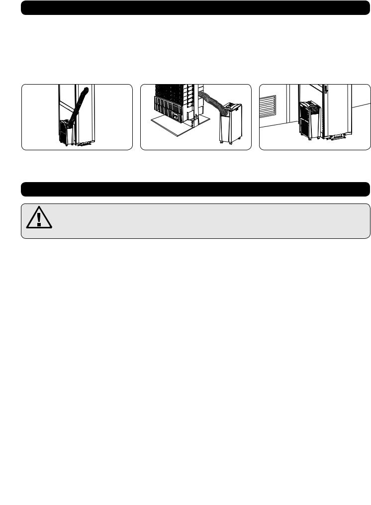
Recommended Applications:
1. Cooling an overheated rack enclosure.
2.Cooling an equipment hot spot inside or outside a rack enclosure.
3. Cooling a small room.
Important Safety Instructions
SAVE THESE INSTRUCTIONS
This manual contains instructions and warnings that should be followed during the installation, operation and storage of this product. Failure to heed these warnings may affect your warranty.
Warnings
•The individual user should determine prior to use whether this device is suitable, adequate or safe for the use intended. Since individual applications are subject to great variation, the manufacturer makes no representation or warranty as to the suitability or fitness of this device for any specific application.
•Install the unit indoors, away from extreme temperatures or humidity, direct sunlight, dust and conductive contaminants.
•Leave adequate space around the unit for ventilation, with rear and vented sides not less than 20 inches (51 cm) from walls or other obstacles.
•Install the unit on a flat surface with a gradient no more than 10°.
•Connect the unit directly to a grounded AC power outlet. Failure to do so may cause an electric shock or fire.
•The power supply for the unit must be rated in accordance with the unit’s nameplate.
•Do not modify the plug nor use an adapter that would eliminate the ground connection.
•Do not use an extension cord to connect the unit to an AC outlet. Use only the power cord that came with the unit.
•Comply with all applicable wiring and safety regulations, such as National Electrical Code (NEC) in the United States.
•Do not plug additional equipment into the outlet where the unit is plugged in. Overloading the outlet may cause an electric shock or fire.
•Do not attempt to turn the unit on or off by connecting or disconnecting the AC plug. A serious electric shock may occur. Use the ON/OFF button to turn the unit on or off.
•Turn the unit off and unplug it from the AC outlet before performing maintenance.
•Before connecting the unit to a dedicated drainage system, turn it off and unplug it. There is a risk of electric shock while the unit is plugged in.
•Maintenance should be performed by trained personnel only.
•Do not use thinners, alcohol, detergents or abrasive brushes to clean the unit’s cabinet. These items may damage the cabinet.
•Do not pour water over the unit. This may cause an electric shock and damage the unit.
•Do not operate the unit without the air filter. This may cause dust accumulation that may damage the unit.
•Do not attempt to operate the unit in a room with inadequate air circulation. Provide makeup air in accordance with applicable building codes.
•Do not place objects on top of the unit.
•Use of this equipment in life support applications where failure of this equipment can reasonably be expected to cause the failure of the life support equipment or to significantly affect its safety or effectiveness is not recommended. Do not use this equipment in the presence of a flammable anesthetic mixture with air, oxygen or nitrous oxide.
2

Features
Front View
AControl Panel
BRecessed Handles
CAir Filter Covers
DDrainage Outlet
ECasters
FFront Panel
GCool Air Output
HLouvered Vent Insert (Pre-Installed)
ICooling Duct Adapter (Optional)
JRear Panel
KWarm Air Exhaust
LEvaporator Drainage Outlet
M Evaporator Filter
N Condenser Filter
Control Panel
A“POWER” Button
B“FUNCTION” Button
C“TIMER” Button
D“FAN SPEED” Button
E“QUIET” Button
FTemperature Control Buttons
GNumeric Display
HOperating Mode LEDs
I Fan Speed Mode LEDs
I A
 B
B 

 B
B
H 
 K
K 


 M G
M G
C
L
F J
N
D
E E
H G
F B C D I A E F
3
Installation
Warning: After removing the unit from the shipping container, check for damage or missing parts. (Refer to the parts list below.) If you notice a problem, visit www.tripplite.com/support for service. Do not attempt to operate a damaged unit.
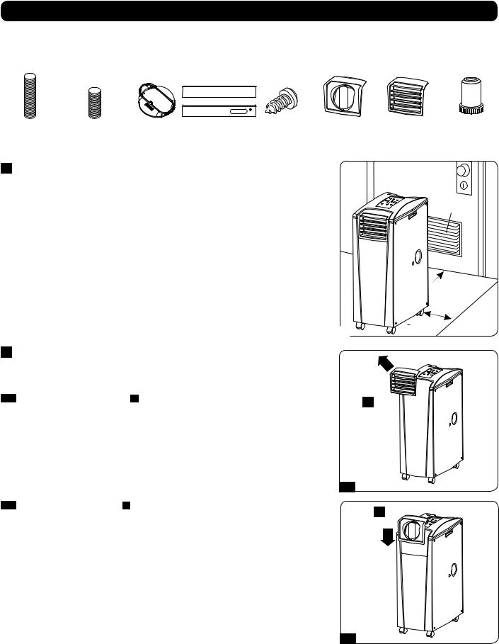
Accessory Parts List:
Exhaust Duct |
Cooling Duct |
Exhaust Duct |
Adjustable |
Self-Tapping |
2 Duct Adapters |
Louvered Vent |
Drainage |
(Longer Tube) |
(Shorter Tube) |
Adapter |
Exhaust Panel |
Screw |
(1 Pre-Installed) |
Insert |
Plug |
|
|
|
(2 Sections) |
|
|
(Pre-Installed) |
(2 Pre-Installed) |
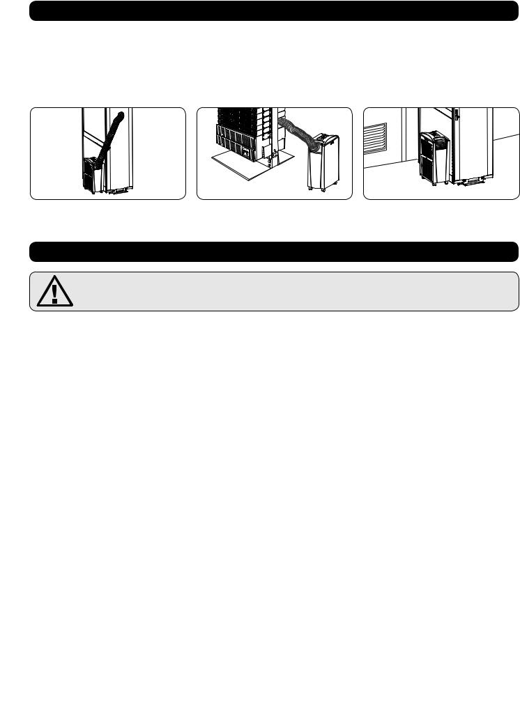
1 Unit Placement
Place the unit on a flat, level surface near a grounded AC outlet rated in accordance with the unit nameplate (90-110% of specified voltage). Leave adequate space around the unit for ventilation, with rear and vented sides not less than 20 inches (51 cm) from walls or other obstacles. Place the unit in a location with convenient access to a drop ceiling or window to provide the straightest, shortest path available for the flexible exhaust duct. If you plan to use the flexible cooling duct to focus cool air on a specific rack enclosure or device, place the unit near the targeted rack enclosure or device to provide the straightest, shortest path available for the cooling duct.
Warning: Do not use an extension cord to connect the unit to an AC outlet. Use only the power cord that came with the unit.
Note: If the unit will operate in a confined space (such as closet), you must supply makeup air in order to maintain airflow efficiency. A 100 in.2 (645 cm2) or larger vent installed near the bottom of the door should supply adequate makeup air for a typical closet. Consult applicable building codes for more information.
Exhaust hose not shown—see Section 3. |
|
1 |
2 Cooling Duct Connection (Optional)
The pre-installed louvered vent insert is appropriate for room cooling applications. If you plan to cool a room, skip step 2 and proceed to step 3. If you plan to use the flexible cooling duct to focus cool air on a specific device or rack enclosure, follow the instructions below.
2-1 Remove the louvered vent insert A by pulling it outward and upward.
2-1
2-2 Align the cooling duct adapter A in the vent opening and push it downward until it snaps into place.
100 in.2 (645 cm2) Vent (For Confined Spaces)
 > 20 in (51 cm)
cm) |
WALL |
|
A 

A 
2-2
4
Installation (continued)
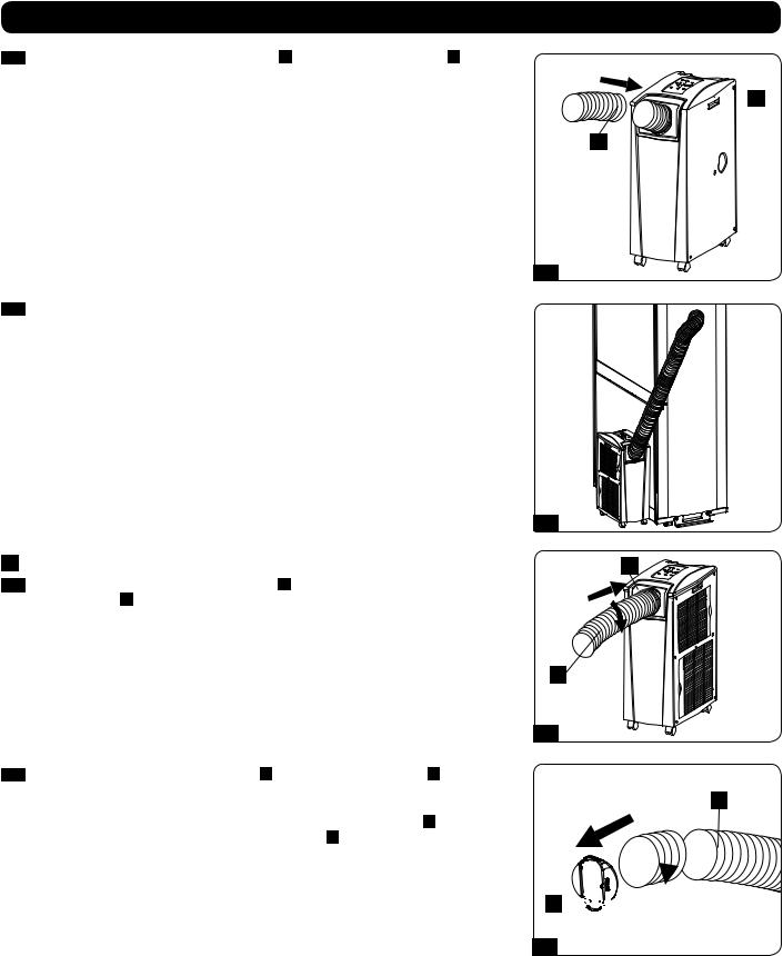
2-3 Connect the flexible cooling duct (shorter tube A ) to the cooling duct adapter B . Align the duct with the circular adapter opening, push the duct downward and turn the duct clockwise until it screws into the adapter solidly.
2-3
2-4 Place the other end of the cooling duct near the air intake of the target device or rack enclosure, using the straightest, shortest path available. If you plan to cool a rack enclosure, place the end of the cooling duct over a perforated area near the top of the enclosure’s front door (or near the top of the bank of equipment that requires cooling). Cool air will sink and spread across the air intakes at the front of the rack enclosure.
2-4
3 Exhaust Duct Connection
3-1 Connect the flexible exhaust duct (longer tube A ) to the warm air exhaust vent on the rear panel of the unit B . Align the duct with the circular vent opening, push the duct inward and turn the duct clockwise until it screws into the exhaust vent solidly.
A
A
1
1 
 2
2


B
2 |
B
3-2 Connect the other end of the exhaust duct A to the exhaust duct adapter B . Align the duct with the circular adapter opening, push the duct inward and turn the duct clockwise until it screws into the adapter solidly.
If you plan to connect the exhaust duct to a drop ceiling, proceed to step 4 . If you plan to connect the exhaust duct to a window, proceed to step 5 .
3-1
1
A 


3-2
B
2
5
Installation (continued)
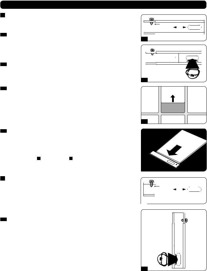
4 Drop Ceiling Exhaust Connection
Warning: Some ceilings may require modified installation procedures. The user |
Self-Tapping Screw |
must determine the fitness of hardware and procedures before installing. The |
|
procedures described in this manual may not be appropriate for all applications. |
|
4-1 Choose a removable drop ceiling panel near the unit to provide the straightest, shortest |
|
path available for the flexible exhaust duct. Measure the width of the ceiling panel, |
4-1 |
including the portion that rests on the ceiling grid. Combine the two sections of the |
|
adjustable exhaust panel, then adjust the exhaust panel to match the width of the ceiling |
|
panel. After the exhaust panel is set to the correct width, use the included self-tapping |
|
screw to lock it in place. Note: The exhaust panel can adjust from 26.6 to 49.2 inches |
|
(67.5 to 125 cm). |
|
4-2 Insert the exhaust duct adapter into the oblong hole in the adjustable exhaust panel. The |
|
adapter will snap into place. |
|
|
4-2 |
4-3 Slide the ceiling panel out of the way and place the exhaust panel inside the ceiling space. |
Ceiling Panel |
Allow the exhaust panel to rest on top of the ceiling grid. Note: There must be at least 10 |
(From Below) |
inches (25.4 cm) of open space above the exhaust panel to allow adequate airflow. |
|
4-3
4-4 Slide the ceiling panel back into place so that it adjoins the exhaust panel and closes any
gaps in the ceiling. A tight seal will permit maximum cooling efficiency. If the installation is
permanent, trim the ceiling panel so it doesn’t overlap the ceiling grid. Ceiling Panel (From Above)
Note: The flexible exhaust duct can extend to a maximum length of 118 inches (300 cm). Provide the straightest, shortest path available. Excessive bending or stretching of the duct will
reduce cooling efficiency.
After completing step 4 , proceed to step 6 .
4-4 |
Exhaust Panel |
|
5 Window Exhaust Connection
Warning: Some windows may require modified installation procedures. The user |
Self-Tapping Screw |
|
|
|||||
must determine the fitness of hardware and procedures before installing. The |
|
|
||||||
|
|
|
|
|
||||
procedures described in this manual may not be appropriate for all applications. |
|
|
|
|
|
|||
|
Measure the window opening. Combine the two sections of the adjustable exhaust panel, |
|
|
|
|
|
||
5-1 |
|
|
|
|
|
|||
|
|
|
|
|
|
|
|
|
|
then adjust the exhaust panel to match the width of the window opening. After the exhaust |
5-1 |
|
|
|
|
|
|
|
panel is set to the correct width, use the included self-tapping screw to lock it in place. |
|
|
|
|
|
|
|
|
Note: The exhaust panel can adjust from 26.6 to 49.2 inches (67.5 to 125 cm). It is |
|
|
|
|
|
||
|
compatible with vertical and horizontal mounting. |
|
|
|
|
|
||
|
|
|
|
|
||||
5-2 Insert the exhaust duct adapter into the oblong hole in the adjustable exhaust panel. The adapter will snap into place.
5-2
6
Installation (continued)
5-3 Insert the exhaust panel into the window opening, then close the window against the exhaust panel. A tight seal will permit maximum cooling efficiency. Note: There must be at least 10 inches (25.4 cm) of open space behind the exhaust panel to allow adequate airflow.
Note: The flexible exhaust duct can extend to a maximum length of 118 inches (300 cm). Provide the straightest, shortest path available. Excessive bending or stretching of the duct will reduce cooling efficiency.
Horizontal Window |
Opening |
INCORRECT CORRECT
Vertical |
Window |
Opening |
5-3 |
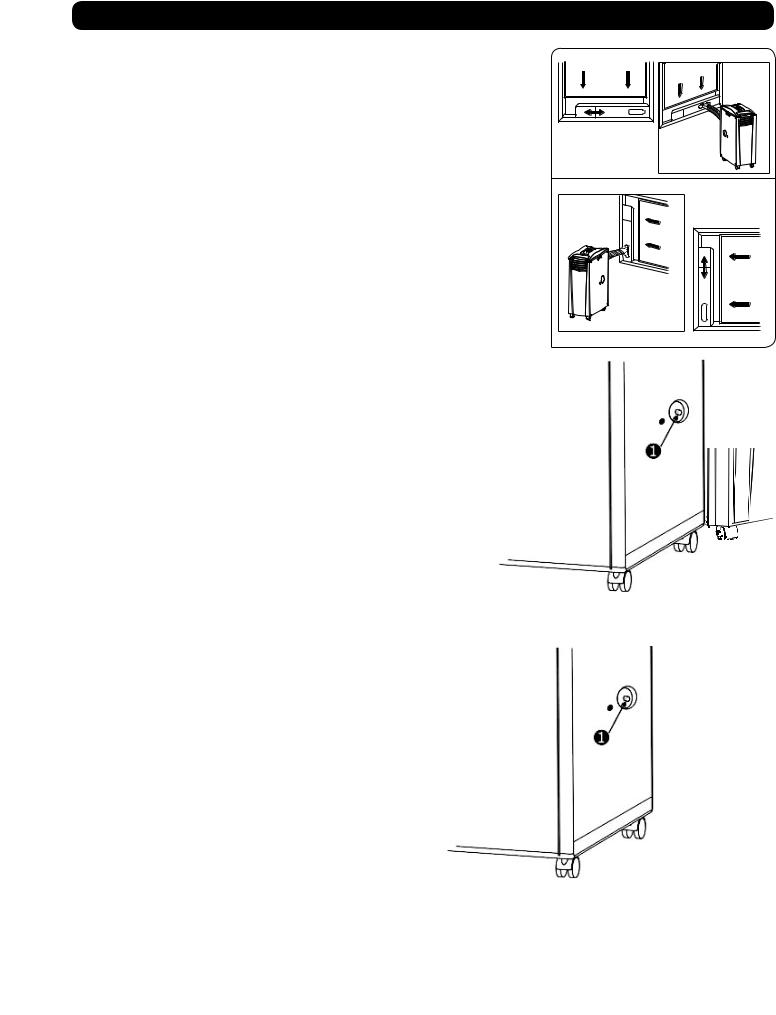
6 Drainage Plug Insertion
Warning: The unit’s built-in re-evaporator will not function until you insert the drainage plug into the drainage outlet.
When the unit cools or dehumidifies, condensation forms. The unit has a built-in re-evaporator that allows it to expel condensation through the warm air exhaust stream. This feature allows the unit to operate indefinitely without requiring you to empty a water collection tank. The unit ships with both the upper and lower drainage plugs pre-installed.
6-1 Cooling Mode with Re-Evaporation
Both plugs must remain installed to enable re-evaporation of condensation.
6-2 Cooling Mode without Re-Evaporation
To use Cooling mode without re-evaporating condensation, remove the bottom drain plug and route user-supplied drain line to external drainage. The top drain plug must remain installed.
6-3 Dehumidify Mode
When using the unit in Dehumidify mode, remove the top drain plug and route usersupplied drain line to external drainage. The bottom drain must remain installed. This will maximize the amount of water removed from the air.
Note: If the drainage system becomes clogged, a small internal reservoir will collect condensation. If the drainage system is not cleared before the internal reservoir fills, the unit will shut down automatically.
Warning: Before connecting the unit to a dedicated drainage system, turn it off and unplug it. There is a risk of electric shock while the unit is plugged in.
Note: If your building’s cooling system has night or weekend thermostat setbacks, has periodic shutdowns, or has limited cooling capacity, you may need to consider alternatives to the standard installation. This product is meant to be used as a supplemental cooling device, and cannot make up for significant fluctuations in building temperature or humidity.
Low Temperature Operation
The SRCOOL12K is a high performance cooler, capable of producing very cold air output. When using the SRCOOL12K in environments that are already cold (20° C / 68° F or less), Tripp Lite recommends using the Dehumidify Mode only. This will allow the unit to continue to provide the supplemental cooling while preventing any evaporator icing issues caused by the low room temperature.
6-1
TO EXTERNAL
DRAIN
6-2
TO EXTERNAL
DRAIN
6-3
7
Operation
Warning: Install the unit according to the instructions in the “Installation” section before attempting to operate it.
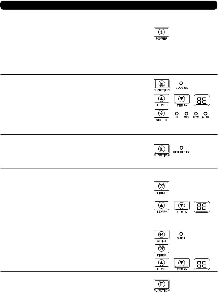
Power
Turn the unit on or off by pressing the “POWER” button.
The unit has a three-minute compressor delay in order to prevent potential circuit overloads at start up.
Automatic Restart Feature
The unit will turn on and resume operation automatically when power is restored after a power outage. The unit will use the same settings that it used immediately before the power outage occurred. Note: If the power outage is brief, the unit will run the fan alone for three minutes before resuming normal operation. The delay allows the compressor to depressurize so the unit will function properly when it enters Cool mode.
Cool Mode
Pressing the “FUNCTION” button cycles between Cool mode and Dehumidify mode. The “COOLING” LED illuminates when Cool mode is active.
Press the TEMP+ and TEMPbuttons to set the temperature in Cool mode. The selected temperature is shown on the numeric display. Once set, the desired temperature will blink five times after which the display will show the current room temperature.
Press the “FAN SPEED” button to cycle between high, medium and low fan speeds. An LED illuminates to indicate the selected fan speed. When speed is set on AUTO, the unit will automatically select a fan speed based on the set and ambient temperatures. If ambient temperature is lower than the set temperature, the fan will run and the “COOLING” LED will blink to indicate that the compressor is off. When cooling resumes, the “COOLING” LED will remain illuminated.
Dehumidify Mode
Pressing the “FUNCTION” button cycles between Cool mode and Dehumidify mode.
The “DEHUMIDIFY” LED illuminates when Dehumidify mode is active. In Dehumidify mode, the fan runs at a fixed speed and temperature controls are irrelevant. For optimal performance
in Dehumidify mode, close windows and doors, remove the top drain plug and route usersupplied drain line to external drainage.
Timer
The “TIMER” button allows you to schedule the unit to turn on or off automatically.
Timer On (Note: The unit must be off to activate the Timer On function. Confirm that mode, temperature and fan speed settings are correct before activating the Timer On function.)
Activate the timer by pressing the “TIMER” button. Press the TEMP+ and TEMPbuttons to set the delay (in hours) before the unit will turn on. The number of hours is shown on the numeric display. The number will flash on the screen five times before returning to the current temperature.
Timer Off (Note: The unit must be on to activate the Timer Off function.) Activate the timer by pressing the “TIMER” button. Press the TEMP+ and TEMPbuttons to set the delay (in hours) before the unit will turn off. The number of hours is shown on the numeric display. The number will flash on the screen five times before returning to the current temperature.
Quiet Control Mode
The unit includes a Quiet Control mode which regulates the cooling via the timer and microprocessor to achieve quieter operation levels when noise is an issue.
To activate, press the “QUIET” button. The Quiet LED will turn on. Set the desired temperature and then set the timer to the duration of the Quiet Control mode cycle. During the course of the cycle, the microprocessor memory will adjust the preset temperature by 0.9°F (0.5°C) every 30 minutes until it reaches the desired temperature. Once the temperature is reached, the unit will maintain the temperature for the duration of the set time.
Changing Degree Units
The unit can display temperature in both Celsius and Fahrenheit. The default setting for the
SRCOOL12K is Fahrenheit and the SRXCOOL12K is Celsius.
To toggle between temperature modes, put the unit in standby mode. The air conditioner is in standby mode when it is plugged into live AC power, but powered off. Then, hold the
“FUNCTION” key for 10 seconds until a beep sounds.
8
Operation (continued)
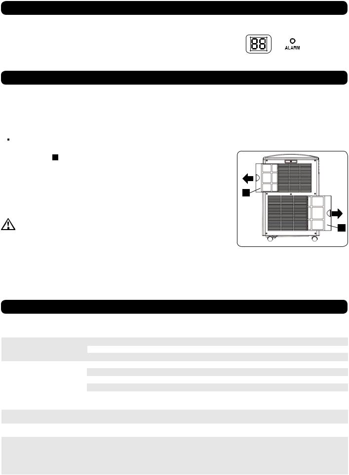
Alarm
When the water tank is full, the unit will display the message “E4” on its screen. To resume normal function, turn the unit off, remove the drainage plug and drain the excess water from the unit. Replace the plug and turn the unit on to begin cooling.
Maintenance
Periodic maintenance extends the unit’s lifespan and permits maximum operating efficiency.
Cleaning the Air Filters
It is important to keep the air filters clean and free of dust. When the filters are dirty or clogged with dust, it decreases cooling efficiency and can threaten air quality. Tripp Lite recommends cleaning the filters at least once every two weeks.
 Before cleaning the filters, turn the unit off and unplug it! There is a risk of electric shock while the unit is plugged in.
1.Turn the unit off and unplug it.
2.Remove the filters A by sliding them out of the cabinet.
3.Wash the filters in warm water with a neutral detergent. Do not put the filters into a dishwasher or use harsh detergents or chemicals. Allow the filters to air dry completely after
washing. Note: Do not use water hotter than 104° F (40° C) to clean the filters.
4. Replace the filters by sliding them back into their original position. |
A |
|
5. Plug the unit in and resume normal operation.
Cleaning the Cabinet
Before cleaning the cabinet, turn the unit off and unplug it! There is a risk of |
|
electric shock while the unit is plugged in. |
A |
1.Turn the unit off and unplug it.
2.Wipe the unit with a dry, non-abrasive cloth. Do not use gasoline, benzene, thinners or other harsh chemicals that may damage the surface. Do not pour water directly over the unit or into the working parts. This causes a risk of electrical shock and deterioration of electrical components and wiring insulation.
3.In extreme cases, wipe the unit with a damp cloth to remove residue.
Troubleshooting
Review the possible solutions below. If the problem persists, please visit www.tripplite.com/support for service.
Problem |
Possible Cause |
Possible Solution |
The unit does not function. |
The unit is turned off. |
Turn the unit on. (See “Operation” section.) |
|
|
|
|
The unit is not plugged in. |
Plug the unit into a suitable outlet. |
|
|
|
|
Main power is off. |
Check fuses or circuit breaker. |
|
|
|
Cooling performance is unsatisfactory. |
The air exhaust or intake is blocked. |
Confirm that all ducts and intakes are clear of obstructions. |
|
|
|
|
The temperature setting is too high. |
Adjust the temperature setting. |
|
The fan speed setting is too low. |
Adjust the fan setting. |
|
|
|
|
The air filters are dirty. |
Clean the air filters. |
|
|
|
|
The wattage of the rack enclosure, the size of the room or the |
Install additional units or contact Tripp Lite for additional cooling |
|
ambient temperature exceeds the cooling capacity of a single |
solutions suitable for your application. |
|
unit. |
|
|
|
|
The unit leaks water. |
The drainage plug is not installed. |
Insert the drainage plug in the drainage outlet. (See “Installation” |
|
|
section.) |
|
|
|
The unit generates excessive noise or |
The unit is on an uneven or unstable surface. |
Move the unit to a level, stable surface. |
vibration. |
|
|
|
|
|
The unit has ice or frost buildup. |
The unit is operating in an environment with excess humidity. |
OPTION 1: Turn off the unit, and let the unit defrost. Once |
|
|
defrosted, ensure the unit is operating with the fan speed set |
|
|
on HIGH. |
|
|
OPTION 2: Turn off the unit, and let the unit defrost. Once |
|
|
defrosted, operate the unit in DEHUMIDIFY MODE, or increase |
|
|
the desired temperature setpoint. |
|
|
|
9
Troubleshooting (continued)
Additional Display Error Codes
The Tripp Lite SRCOOL12K has the ability to continually monitor itself. Should an error occur, the display will show one of 5 error codes below:
Error Code |
Description |
|
|
E0 |
Internal Communication Error |
|
|
E1 |
Indoor Temperature Sensor Error |
E2 |
Internal Temperature Sensor Error |
E3 |
Refrigerant Error |
E4 |
Water Full |
Code E4 can be cleared by emptying the water tank. Consult the owner’s manual for details.
For Codes E0, E1, E2, and E3 follow these steps:
1.Power cycle the unit by unplugging it from the source for 5 minutes.
2.Plug the unit back in.
3.Restart the unit.
If the code remains clear, continue to operate the unit as normal. If the code returns, please contact Tripp Lite for further instructions.
Storage and Service
Storage
Before storing the unit, confirm that the ducts and vents are secured or removed and cared for properly. Also confirm that the unit is drained of condensation.
Service
Your Tripp Lite product is covered by the warranty described in this manual. A variety of Extended Warranty and On-Site Service Programs are also available from Tripp Lite. For more information on service, visit www.tripplite.com/support. Before returning your product for service, follow these steps:
1.Review the installation and operation procedures in this manual to insure that the service problem does not originate from a misreading of the instructions.
2.If the problem continues, do not contact or return the product to the dealer. Instead, visit www.tripplite.com/support.
3.If the problem requires service, visit www.tripplite.com/support and click the Product Returns link. From here you can request a Returned
Material Authorization (RMA) number, which is required for service. This simple on-line form will ask for your unit’s model and serial numbers, along with other general purchaser information. The RMA number, along with shipping instructions will be emailed to you. Any damages (direct, indirect, special or consequential) to the product incurred during shipment to Tripp Lite or an authorized Tripp Lite service center is not covered under warranty. Products shipped to Tripp Lite or an authorized Tripp Lite service center must have transportation charges prepaid. Mark the RMA number on the outside of the package. If the product is within its warranty period, enclose a copy of your sales receipt. Return the product for service using an insured carrier to the address given to you when you request the RMA.
Warranty and Warranty Registration
Warranty
1-YEAR LIMITED WARRANTY
Seller warrants this product, if used in accordance with all applicable instructions, to be free from original defects in material and workmanship for a period of 1 year from the date of initial purchase. If the product should prove defective in material or workmanship within that period, Seller will repair or replace the product, in its sole discretion. Service under this Warranty can only be obtained by your delivering or shipping the product (with all shipping or delivery charges prepaid) to: Tripp Lite, 1111 W. 35th Street, Chicago, IL 60609 USA. Seller will pay return shipping charges.
THIS WARRANTY DOES NOT APPLY TO NORMAL WEAR OR TO DAMAGE RESULTING FROM ACCIDENT, MISUSE, ABUSE OR NEGLECT. SELLER MAKES NO EXPRESS WARRANTIES OTHER THAN THE WARRANTY EXPRESSLY SET FORTH HEREIN. EXCEPT TO THE EXTENT PROHIBITED BY APPLICABLE LAW, ALL IMPLIED WARRANTIES, INCLUDING ALL WARRANTIES OF MERCHANTABILITY OR FITNESS, ARE LIMITED IN DURATION TO THE WARRANTY PERIOD SET FORTH ABOVE; AND THIS WARRANTY EXPRESSLY EXCLUDES ALL INCIDENTAL AND CONSEQUENTIAL DAMAGES. (Some states do not allow limitations on how long an implied warranty lasts, and some states do not allow the exclusion or limitation of incidental or consequential damages, so the above limitations or exclusions may not apply to you. This Warranty gives you specific legal rights, and you may have other rights which vary from jurisdiction to jurisdiction).
WARNING: The individual user should determine prior to use whether this device is suitable, adequate or safe for the use intended. Since individual applications are subject to great variation, the manufacturer makes no representation or warranty as to the suitability or fitness of this device for any specific application.
WARRANTY REGISTRATION
Visit www.tripplite.com/warranty today to register the warranty for your new Tripp Lite product. You’ll be automatically entered into a drawing for a chance to win a FREE Tripp Lite product!* * No purchase necessary. Void where prohibited. Some restrictions apply. Open to U.S. residents only. See www.tripplite.com for details.
Regulatory Compliance Identification Numbers
For the purpose of regulatory compliance certifications and identification, your Tripp Lite product has been assigned a unique series number. The series number can be found on the product nameplate label, along with all required approval markings and information. When requesting compliance information for this product, always refer to the series number. The series number should not be confused with the marking name or model number of the product.
WEEE Compliance Information for Tripp Lite Customers and Recyclers (European Union)
Note: This statement applies to products marked with the WEEE logo.
Under the Waste Electrical and Electronic Equipment (WEEE) Directive and implementing regulations, when customers buy new electrical and electronic equipment from Tripp Lite they are
entitled to:
• Send old equipment for recycling on a one-for-one, like-for-like basis (this varies depending on the country)
• Send the new equipment back for recycling when this ultimately becomes waste
Tripp Lite has a policy of continuous improvement. Product specifications are subject to change without notice.
1111 W. 35th Street, Chicago, IL 60609 USA • www.tripplite.com/support
10
Manual del Propietario
Unidad Portátil de Aire Acondicionado
SRCOOL12K (120V, 60 Hz)
SRXCOOL12K (230V, 50 Hz)
Introducción |
12 |
Instrucciones Importantes de Seguridad 12
Características |
13 |
Instalación |
14 |
Operación |
18 |
Mantenimiento |
19 |
Solución de Problemas |
20 |
Almacenamiento y Servicio |
20 |
Garantía y Registro de Garantía |
20 |
English |
1 |
Français |
21 |
Русский |
31 |
MÁS DE
1111 W. 35th Street, Chicago, IL 60609 USA • www.tripplite.com/support
Copyright © 2013 Tripp Lite.
11
Introducción
La Unidad independiente Portátil de Aire Acondicionado proporciona 12,000 BTU (hasta 3.4 kW) de capacidad complementaria de enfriamiento. Diseñada para ambientes de TI, es ideal para enfriar gabinetes de rack sobrecalentados, puntos calientes de equipo de TI y gabinetes de cableado de red sin acceso al aire acondicionado de la instalación. La Unidad Portátil de Aire Acondicionado puede enfocar aire frío mediante su ducto flexible de enfriamiento o enfriar una sala pequeña a través de su ventila con persianas. Además filtra y seca el aire para mejorar las condiciones de operación y confiabilidad del equipo. El condensado es re-evaporado para una operación libre de goteo, de modo que usted no gaste tiempo vaciando los tanques colectores de agua. El diseño independiente no requiere plomería o circuitos especiales, de modo que la instalación es rápida y fácil. El refrigerante ecológico R410A cumple con los estándares ambientales internacionales.
Aplicaciones Recomendadas
1. Enfriamiento de un gabinete de rack sobrecalentado.
2. Enfriamiento de un punto caliente de equipo dentro o fuera de un gabinete de rack.
3. Enfriamiento de una sala pequeña.
Instrucciones de seguridad importantes
GUARDE ESTAS INSTRUCCIONES
Este manual contiene instrucciones y advertencias que deben seguirse durante la instalación, el funcionamiento y el almacenamiento de este producto. Si no tiene en cuenta estas advertencias se puede anular la garantía.
Advertencias
•Antes de usar este dispositivo, cada usuario debe determinar si es apto, adecuado o seguro para el uso que pretende darle. Dado que las aplicaciones individuales están sujetas a diversas variaciones, el fabricante no representa ni garantiza la idoneidad o condición de este dispositivo para cualquier aplicación específica.
•Instale la unidad en interiores, alejada de temperaturas o humedad extremas, la luz solar directa, polvo y contaminantes conductores.
•Deje espacio adecuado para ventilación alrededor de la unidad, con la parte posterior y costados ventilados a no menos de 51 cm [20 pulgadas] de paredes u otros obstáculos.
•Instale la unidad sobre una superficie plana con una inclinación no mayor de 10º.
•Conecte la unidad a un tomacorriente de CA conectado directamente a tierra. La omisión en esto puede originar una descarga eléctrica o un incendio.
•La alimentación de energía para la unidad debe estar especificada de acuerdo con la placa de identificación de la unidad.
•No modifique la clavija ni utilice un adaptador que elimine la conexión a tierra.
•No utilice cables de extensión para conectar la unidad a un tomacorriente de CA. Use sólo el cable de alimentación suministrado con la unidad.
•Cumpla todos los reglamentos aplicables de cableado y seguridad, como el Código Eléctrico Nacional (NEC) en los EE.UU.
•No enchufe equipo adicional en el tomacorrientes en donde esté conectada la unidad. La sobrecarga del tomacorriente puede causar una descarga eléctrica o un incendio.
•No intente encender o apagar la unidad conectando o desconectando el enchufe de CA. Puede ocurrir una severa descarga eléctrica. Use el botón de ON/OFF para encender y apagar la unidad.
•Apague la unidad y desenchúfela del tomacorrientes de CA antes de realizar el mantenimiento.
•Antes de conectar la unidad a un sistema de drenaje dedicado, apague la unidad y desenchúfela. Existe un riesgo de descarga eléctrica cuando la unidad está enchufada.
•El mantenimiento sólo debe realizarlo personal capacitado.
•No use adelgazantes, alcohol, detergentes o cepillos abrasivos para limpiar el gabinete de la unidad. Estos artículos pueden dañar el gabinete.
•No vierta agua sobre la unidad. Esto puede causar una descarga eléctrica y dañar la unidad.
•No opere la unidad sin el filtro de aire. Esto puede causar una acumulación de polvo que puede dañar la unidad.
•No intente operar la unidad en un cuarto con circulación inadecuada de aire. Proporcione aire complementario de acuerdo con los códigos de construcción aplicables.
•No coloque objetos en la parte superior de la unidad.
•No se recomienda usar este equipo en aplicaciones de mantenimiento artificial de la vida, donde se puede esperar razonablemente que su falla cause la falla del equipo de mantenimiento de la vida o que afecte de manera importante su seguridad o eficiencia. No use este equipo en presencia de mezclas anestésicas inflamables con aire, oxígeno u óxido nitroso.
12
 Loading...