


Warranty |
|
|
|
chance |
|||||
|
Lite |
|
|||||||
Registration |
a |
|
product! |
||||||
|
|
|
|
|
for |
|
|||
|
|
|
|
|
.com/warranty |
||||
|
|
|
|
today |
|
|
|
|
|
|
|
online |
Tripp |
|
|
|
|
||
|
|
|
|
FREE |
|
|
|
|
|
Register |
|
a |
.tripplite |
|
|
|
|
||
|
win |
|
|
|
|
|
|
||
to |
|
|
|
|
|
|
|
||
|
www |
|
|
|
|
|
|||
Owner’s Manual
SMART1500LCDXL
Not suitable for mobile applications
|
INPUT |
|
|
|
|
K |
H |
|
|
|
|
OUTPUT |
|
|
|
|
|
|
|
|
|
|
LOAD |
|
|
|
|
|
% |
|
|
|
|
TEST BATT |
. |
. |
|
|
|
|
|
||
|
RUNTIME |
|
|
MIN |
|
|
||||
|
SENSITIVITY |
|
SCROLL |
|
|
|||||
|
|
|
|
|
|
|
|
|
|
|
|
|
|
|
|
|
|
|
|
|
|
|
EXTERNAL BATTERY CAPACITY |
|
|
|
||||||
|
|
x |
|
|
|
|
|
|
|
|
|
|
|
|
|
|
|
|
|
|
|
|
MODE |
|
|
|
MUTE |
|
|
|
||
Important Safety Instructions |
2 |
|
Features |
8 |
||||||
Quick Installation |
3 |
|
Storage and Service |
9 |
||||||
Basic Operation |
4 |
|
Warranty Registration |
10 |
||||||
UPS On/Off |
4 |
|
Español |
12 |
||||||
LCD Display |
4 |
|
Français |
22 |
||||||
LCD Features |
4 |
|
|
|
|
|
|
|
||
Display Power Conditions |
5 |
|
|
|
|
|
|
|
||
Enable/Disable Alarm |
5 |
|
|
|
|
|
|
|
||
LCD Brightness |
5 |
|
|
|
|
|
|
|
||
Self-test |
5 |
|
|
|
|
|
|
|
||
Power Sensitivity |
6 |
|
|
|
|
|
|
|
||
Scroll Control |
6 |
|
|
|
|
|
|
|
||
External Battery Settings |
7 |
|
|
|
|
|
|
|
||
Error Messages |
7 |
|
|
|
|
|
|
|
||
1111 W. 35th Street, Chicago, IL 60609 USA www.tripplite.com/support
Copyright © 2011 Tripp1Lite. All rights reserved.
201103012 933072.indb 1 |
3/8/2011 1:43:09 PM |

Important Safety Instructions
SAVE THESE INSTRUCTIONS
This manual contains instructions and warnings that should be followed during the installation, operation and storage of this product. Failure to heed these warnings may affect the warranty.
UPS Location Warnings
•Install your UPS indoors, away from excess moisture or heat, conductive contaminants, dust or direct sunlight.
•For best performance, keep the indoor temperature between 32º F and 104º F (0º C and 40º C).
•Leave adequate space around all sides of the UPS for proper ventilation.
•Do not mount unit with its front or rear panel facing down (at any angle). Mounting in this manner will seriously inhibit the unit’s internal cooling, eventually causing product damage not covered under warranty.
UPS Connection Warnings
•Connect your UPS directly to a properly grounded AC power outlet. Do not plug the UPS into itself; this will damage the UPS.
•Do not modify the UPS’s plug, and do not use an adapter that would eliminate the UPS’s ground connection.
•Do not use extension cords to connect the UPS to an AC outlet.
•If the UPS receives power from a motor-powered AC generator, the generator must provide clean, filtered, computer-grade output.
•The mains socket outlet that supplies the UPS should be easily accessible and located near the UPS.
Equipment Connection Warnings
•Use of this equipment in life support applications where failure of this equipment can reasonably be expected to cause the failure of the life support equipment or to significantly affect its safety or effectiveness is not recommended. Do not use this equipment in the presence of a flammable anesthetic mixture with air, oxygen or nitrous oxide.
•Do not connect surge suppressors or extension cords to the output of your UPS. This might damage the UPS and may affect the surge suppressor and UPS warranties.
•Connect the UPS to an outlet that is adequately protected against excess currents, short circuits and earth faults as part of the building installation.
Battery Warnings
•Your UPS does not require routine maintenance. Do not open your UPS for any reason. There are no user-serviceable parts inside.
•Batteries can present a risk of electrical shock and burn from high short-circuit current.
Observe proper precautions. Do not open the UPS or batteries. There are no user-serviceable parts inside the UPS. Battery replacement should be performed only by authorized service personnel using the same number and type of batteries (Sealed Lead-Acid). The batteries are recyclable. Refer to your local codes for disposal requirements or visit www.tripplite.com/
UPSbatteryrecycling for recycling information.
•When adding an external battery pack, connect only a Tripp Lite recommended battery pack of the correct voltage and type. Do not connect or disconnect the external battery pack when the UPS is operating on battery power. Visit Tripp Lite on the Web at www.tripplite.com/support/ battery/index.cfm to locate the specific battery for your UPS.
2
201103012 933072.indb 2 |
3/8/2011 1:43:09 PM |
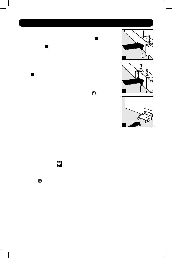
Quick Installation
STEP 1: To install the UPS in a 4-post rack, attach the included mounting hardware to the UPS as shown in diagram A . To mount the
UPS in a 2-post rack, attach the included hardware to the UPS as shown in diagram B . Then, using an assistant if necessary, lift the UPS and attach it to a standard rack or rack enclosure with usersupplied hardware. Caution: If the UPS is placed flat on a surface, do NOT stack any other object directly on top of the unit. The UPS will stand in a tower position without the aid of the included hardware. However, for added stability Tripp Lite recommends that the included hardware be attached as shown in diagram C . The UPS and included hardware are designed for common rack and rack enclosure types and may not be appropriate for all applications.
STEP 2: Plug the UPS into a properly grounded outlet.
After plugging the UPS into a wall outlet, push the MODE button for two seconds to turn the UPS on (see Basic Operation section). Please Note! The UPS will not turn on automatically in the presence of live utility power.
STEP 3: Plug your equipment into the UPS.
* Your UPS is designed to support electronic equipment only. You will overload the UPS if the total VA ratings for all the equipment you connect to the outlets exceeds the UPS’s Output Capacity. To find your equipment’s VA ratings, look on their nameplates. If the equipment is listed in amps, multiply the number of amps by 120 to determine VA. (Example: 1 amp × 120 = 120 VA).If you are unsure if you have overloaded the outlets, run a self-test (see Self-Test description in Basic Operation section).
A |
B |
C |
STEP 4: Optional Installation.
All models include USB and RS-232 communication ports as well as Tel/DSL/network surge protection jacks. These connections are optional; the UPS will work properly without these connections. See the connector's description in the Basic Operation section for connection instructions.
If the LINE POWER icon |
does not illuminate when the UPS is turned ON, try the |
following: |
|
1.Make sure that the UPS is plugged into a live AC outlet.
2.Press the MODE button for 2 seconds to start the UPS. (A beep should sound when the
UPS starts.)
3.If the UPS still does not start, contact Tripp Lite Tech Support for assistance.
3
201103012 933072.indb 3 |
3/8/2011 1:43:10 PM |

Basic Operation
UPS ON/OFF
•Plug the UPS into a grounded outlet.
•Turn the UPS on: Press and hold the MODE button for 2 seconds. The UPS alarm will beep once briefly after 2 seconds have passed.
•Plug equipment into the UPS: Your UPS is designed to support electronic equipment only. You will overload the UPS if the total VA ratings for all the equipment you connect to the “Battery, Surge and Noise Protected” outlets exceeds the UPS’s Output Capacity. To estimate your equipment’s power requirements, look on the nameplate. If the equipment is listed in amps, multiply the number of amps by 120 to determine VA, (Example: 1 amp x 120 = 120 VA). Your UPS is fully loaded when the display indicates 100% load.
•Turn the UPS off: Press and hold the MODE button for 2.5 seconds. The UPS alarm will beep once after 2.5 seconds have passed.
LCD Display
The LCD Display indicates a variety of UPS operational conditions. All descriptions apply when the UPS is plugged into an AC outlet and turned on. The LCD Display can be rotated for easy viewing, regardless of whether the UPS is in a horizontal or vertical (“tower”) position. To rotate the display, insert a small tool in the slots on the sides of the display to pop it out of the UPS housing; rotate the display, and snap it back into the UPS housing.
LCD Features
Tap the MODE button to advance from one display to the next. Use the MUTE button to toggle settings for Power Sensitivity Control, External Battery Setting Control, Scroll Control, Alarm,
LCD Brightness and Self-test functions. The last option displayed before navigating away from this menu option will be the selected setting. When the preferred setting has been selected,
continue by pressing the MODE button. If the screen is idle for 20 seconds, the LCD will return to the home screen, retaining the last selected settings.
4
201103012 933072.indb 4 |
3/8/2011 1:43:10 PM |
Basic Operation continued
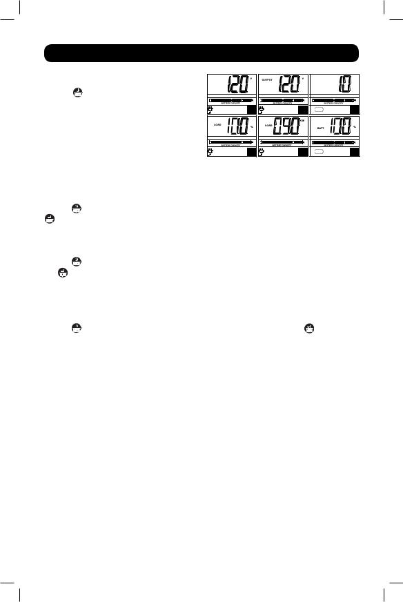
Display Power Conditions
Use the MODE button to advance through power conditions.
1.Voltage In
2.Voltage Out
3.Estimated Runtime (in minutes)
4.Load %
5.Load Wattage*
6.Battery Capacity %
INPUT |
|
1 |
2 |
4 |
5 |
* Load Wattage is displayed in watts up to “999”, and then will be displayed in Kilowatts.
RUNTIME |
MIN |
|
3 |
6 |
Enable/Disable Alarm
Tap the MODE button repeatedly to advance to the LCD display featuring the  icon. Press the
MUTE button to select ON or OFF alarm mode settings. The last option displayed before navigating away from this menu option will be the selected setting.
LCD Brightness
Tap the MODE button repeatedly to advance to the LCD Brightness display marked “LCD”. Press
the MUTE button to select Medium Backlight (default), High Backlight or Dim Backlight. The last option displayed before navigating away from this menu option will be the selected setting.
Note: After 2 minutes of inactivity, the backlight will revert to the Dim setting until a button is pressed.
Self-test
Tap the MODE button repeatedly to advance to the TEST BATT display. Press the MUTE button to initiate the test. The test will last approximately 10 seconds as the UPS switches to battery to test the capacity with a load. Upon completion of the test, the display will indicate PAS or BAD (pass or bad) for 20 seconds, then return to the home screen. Connected equipment can remain on during the test. Do not unplug your UPS, this will remove safe electrical grounding.
5
201103012 933072.indb 5 |
3/8/2011 1:43:11 PM |
Basic Operation continued
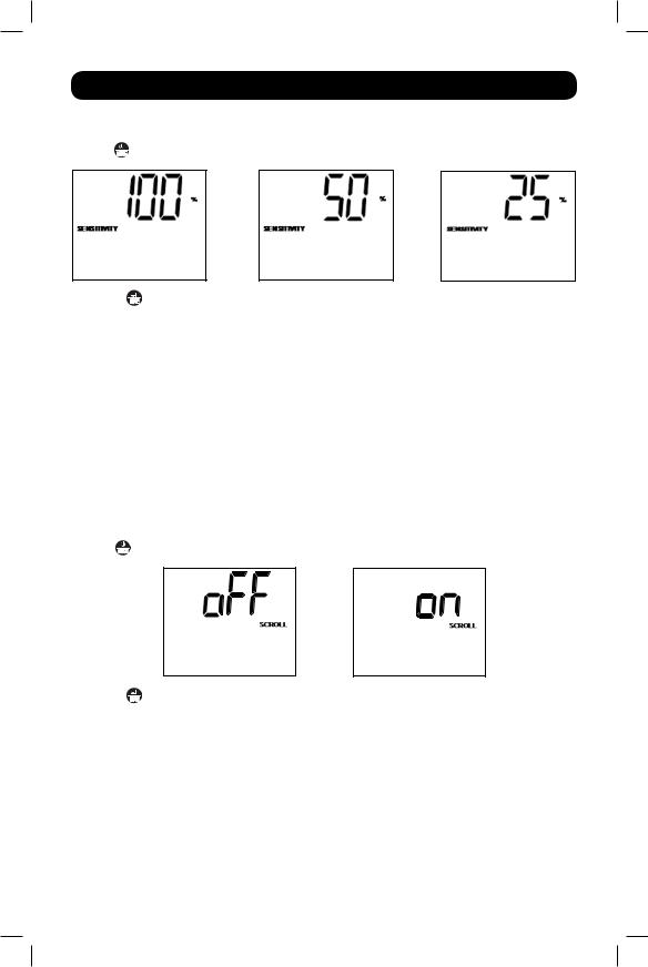
Power Sensitivity
Tap the MODE button repeatedly to advance to Sensitivity display, as shown here:
Press the MUTE button to advance through the options. The last option displayed, before navigating away from this menu option, will be the selected setting.
This setting is normally set to 100%, which enables the UPS to protect against waveform distortions in its AC input. When such distortion occurs, the UPS will normally switch to providing PWM sine wave power from its battery reserves for as long as the distortion is present. In some areas with poor utility power or where the UPS’s input power comes from a backup generator, frequent brownouts and/or chronic waveform distortion could cause the UPS to switch to battery too often, draining its battery reserves. You may be able to reduce how often your UPS switches to battery due to waveform distortion or brownouts by experimenting with different settings. As the setting is reduced, the UPS becomes more tolerant of variations in its input power’s AC waveform. NOTE: When experimenting with different settings, operate connected equipment in a safe test mode so that the effect on the equipment of any waveform distortions in the UPS’s output can be evaluated without disrupting critical operations. The experiment should last long enough to assure that all expected line conditions are encountered.
Scroll Control
Tap the MODE button repeatedly to advance to the Scroll display as shown here:
Press the MUTE button to advance to the next available option. The last option displayed, before navigating away from this menu option, will be the selected setting.
This display option allows the user to select the option to automatically scroll each operating condition of the UPS (such as Input Voltage, Output Voltage and Runtime) automatically.
NOTE:
1.Each condition is displayed in 2 second intervals.
2.If a button is pressed while Scroll Mode is enabled, the scroll function will pause for 10 seconds to allow the user to manually make menu selections.
6
201103012 933072.indb 6 |
3/8/2011 1:43:11 PM |

Basic Operation continued
External Battery Setting Control
Tap the MODE button repeatedly to advance to the External Battery display, as shown here:
EXTERNAL BATTERY |
|
EXTERNAL BATTERY |
|
|
|
|
|
|
Press the MUTE button to advance to the next available option. The last option displayed, before navigating away from this menu option, will be the selected setting.
Note: The Battery Runtime calculation is based on this setting.
This feature setting allows the user to configure the UPS for use with an External Battery Pack or without an External Battery Pack. The Runtime will be automatically reconfigured.
NOTE: Battery Packs cannot be daisychained. Only one Battery Pack can be attached to the UPS.
Error Messages
In the event that the UPS battery requires replacement, the  icon will flash, as well as the
  icon. If there is an overload, the
  ,
,  , and
, and  icons will flash simultaneously along with a numeric read out of the load percentage.
7
201103012 933072.indb 7 |
3/8/2011 1:43:11 PM |

Features
UPS Features
MODE

MUTE

ON/OFF/MODE Button: Press and hold for 2 seconds to turn on the
UPS and 2.5 seconds to turn the UPS off. When the UPS is on, tap this button repeatedly to advance through LCD display screens. If utility power is absent, pressing and holding this button for 2.5 seconds will “cold-start” the UPS; i.e. turn it on and supply power to the outlets from its batteries.
MUTE/ENTER Button: Use this button to toggle selection options for: self-test, enable/disable alarm, LCD brightness, Sensitivity Control,
Scroll Control and the External Battery Setting Control. This button can also be used to temporarily mute an active alarm by briefly pressing it.
Tel/DSL Line Protection Jacks: These jacks protect equipment against surges over a single phone line. Connecting your equipment to these jacks is optional. Your UPS will work properly without this connection. An RJ-11 cable will be included with your UPS.
USB and RS-232 Communication Ports: These ports can connect your UPS to any computer for automatic file saves and unattended shutdown in the event of a power failure. Use with Tripp Lite’s PowerAlert Software (available as a FREE download at www.tripplite.com) and appropriate USB or DB9 cable. Both a USB and a DB9 cable will be included with your UPS.
NOTE:
1.This connection is optional. The UPS will work properly without this connection.
2.This UPS System provides basic communication compatibility with most integrated Windows®, Macintosh®, and Linux® power management applications.
Battery Backup Protected/Surge Protected Outlets: Provide both battery backup and surge protection. Plug your computer, monitor and other critical equipment into these outlets. Note: Do not plug laser printers into the UPS.
Removable Mounting Hardware: Adapts the UPS to either tower or rackmount (2U) applications.
External Battery Connector: Use to connect a Tripp Lite external battery pack for additional runtime. Refer to instructions available with the battery pack for complete connection information and safety warnings.
NOTE: Visit Tripp Lite on the Web at www.tripplite.com/support/battery/index.cfm to locate the specific battery for your UPS.
Resettable Input Circuit Breaker: Protects your electrical circuit from overcurrent draw from the UPS load. If this breaker trips, remove some of the load, then reset it by pressing it in.
8
201103012 933072.indb 8 |
3/8/2011 1:43:13 PM |

Storage and Service
Storage
To avoid battery drain, all connected equipment should be turned off and disconnected from
the UPS. Press and hold the MODE button for 2.5 seconds. Your UPS will be completely turned off (deactivated), and will be ready for storage. If you plan on storing your UPS for an
extended period, fully recharge the UPS batteries every three months. Plug the UPS into a
live AC outlet, turn it on by pressing and holding the MODE button for 2 seconds, and allow the batteries to recharge for 4 to 6 hours. If you leave your UPS batteries discharged for a long
period of time, they will suffer a permanent loss of capacity.
Service
A variety of Extended Warranty and On-Site Service Programs are available from Tripp Lite. For more information on service, visit www.tripplite.com/support. Before returning your product for service, follow these steps:
1.Review the installation and operation procedures in this manual to insure that the service problem does not originate from a misreading of the instructions.
2.If the problem continues, do not contact or return the product to the dealer. Instead, visit www.tripplite.com/support.
3.If the problem requires service, visit www.tripplite.com/support and click the Product Returns link. From here you can request a Returned Material Authorization (RMA) number, which is required for service. This simple on-line form will ask for your unit’s model and serial numbers, along with other general purchaser information. The RMA number, along with shipping instructions will be emailed to you. Any damages (direct, indirect, special or consequential) to the product incurred during shipment to Tripp Lite or an authorized Tripp
Lite service center is not covered under warranty. Products shipped to Tripp Lite or an authorized Tripp Lite service center must have transportation charges prepaid. Mark the RMA number on the outside of the package. If the product is within its warranty period, enclose a copy of your sales receipt. Return the product for service using an insured carrier to the address given to you when you request the RMA.
9
201103012 933072.indb 9 |
3/8/2011 1:43:13 PM |

Warranty Registration
Visit www.tripplite.com/warranty today to register the warranty for your new Tripp Lite product. You’ll be automatically entered into a drawing for a chance to win a FREE Tripp Lite product! *
* No purchase necessary. Void where prohibited. Some restrictions apply. See website for details.
FCC Part 68 Notice (United States Only)
If your Modem/Fax Protection causes harm to the telephone network, the telephone company may temporarily discontinue your service. If possible, they will notify you in advance. If advance notice isn’t practical, you will be notified as soon as possible. You will be advised of your right to file a complaint with the FCC. Your telephone company may make changes in its facilities, equipment, operations or procedures that could affect the proper operation of your equipment. If it does, you will be given advance notice to give you an opportunity to maintain uninterrupted service. If you experience trouble with this equipment’s Modem/Fax Protection, please visit www.tripplite.com/support for repair/warranty information. The telephone company may ask you to disconnect this equipment from the network until the problem has been corrected or you are sure the equipment is not malfunctioning. There are no repairs that can be made by the customer to the Modem/Fax Protection. This equipment may not be used on coin service provided by the telephone company. Connection to party lines is subject to state tariffs. (Contact your state public utility commission or corporation commission for information.)
FCC Notice, Class B
This device complies with part 15 of the FCC Rules. Operation is subject to the following two conditions:
(1) This device may not cause harmful interference, and (2) this device must accept any interference received, including interference that may cause undesired operation.
Note: This equipment has been tested and found to comply with the limits for a Class B digital device, pursuant to part 15 of the FCC Rules. These limits are designed to provide reasonable protection against harmful interference in a residential installation. This equipment generates, uses and can radiate radio frequency energy and, if not installed and used in accordance with the instructions, may cause harmful interference to radio communications. However, there is no guarantee that interference will not occur in a particular installation. If this equipment does cause harmful interference to radio or television reception, which can be determined by turning the equipment off and on, the user is encouraged to try to correct the interference by one or more of the following measures:
•Reorient or relocate the receiving antenna.
•Increase the separation between the equipment and receiver.
•Connect the equipment into an outlet on a circuit different from that to which the receiver is connected.
•Consult the dealer or an experienced radio/TV technician for help.
Any changes or modifications to this equipment not expressly approved by Tripp Lite could void the user’s authority to operate this equipment.
10
201103012 933072.indb 10 |
3/8/2011 1:43:13 PM |
 Loading...