


Warranty |
today .com/warranty |
|
|
|
|||
Registrationwin |
a |
Lite |
|
|
|
||
|
|
for |
|
|
|
||
online |
FREE |
Tripp |
|
Owner’s Manual |
|||
|
|
||||||
|
.tripplite |
|
|
|
|
|
|
Register www |
|
|
|
|
|
|
|
to |
|
|
|
|
|
|
|
chance |
|
|
|
|
|
|
|
product! |
|
|
SmartPro |
® |
2U Rackmount |
||
|
|
|
|
Intelligent, Line-Interactive UPS Systems |
|||
|
|
|
|
|
120V Sine Wave Output • 750VA—1,000VA |
||
|
|
|
|
SMART750RMXL2U |
SMART1000RM2U |
||
|
|
|
|
|
(AGSM8268) |
|
(AGSM8267) |
Not suitable for mobile applications.
Important Safety Instructions |
2 |
Mounting |
4 |
Quick Installation |
6 |
Optional Installation |
7 |
Basic Operation |
9 |
Storage and Service |
17 |
Battery Replacement |
18 |
Warranty Registration |
20 |
Español |
21 |
Français |
41 |
1111 W. 35th Street, Chicago, IL 60609 USA
www.tripplite.com/support
Copyright © 2012 Tripp Lite. All rights reserved. 1SmartPro® is a registered trademark of Tripp Lite.
201205048 93-3149.indb 1 |
6/19/2012 11:33:27 AM |

Important Safety Instructions
SAVE THESE INSTRUCTIONS
This manual contains important instructions that should be followed during the installation, operation and storage of this product. Failure to heed these warnings may affect the warranty.
UPS Location Warnings
•Use caution when lifting the UPS. Because of the considerable weight of all rackmount UPS systems, at least two people should assist in lifting and installing them.
•Install the UPS indoors, away from excess moisture or heat, dust or direct sunlight.
•For best performance, the ambient temperature near the UPS should be between 0° C and 40° C (between 32° F and 104° F).
•Leave adequate space around all sides of the UPS for proper ventilation. Do not obstruct its vents or fan openings.
•When mounting the UPS system in a tower orientation, make sure the LCD Screen panel is at the top of the UPS, not at the bottom.
•Do not mount unit with its front or rear panel facing down (at any angle). Mounting in this manner will seriously inhibit the unit’s internal cooling, eventually causing product damage not covered under warranty.
UPS Connection Warnings
•The UPS contains its own energy source (battery). The output terminals may be live even when the UPS is not connected to an AC supply.
•Connect the UPS to a properly grounded AC power outlet. Do not modify the UPS’s plug in a way that would eliminate the UPS’s connection to ground. Do not use adapters that eliminate the UPS’s connection to ground.
•Do not plug the UPS into itself; this will damage the UPS and void your warranty.
•If you are connecting the UPS to a motor-powered AC generator, the generator must provide filtered, frequency-regulated computer-grade output. Connecting the UPS to a generator will void its Ultimate Lifetime Insurance.
Equipment Connection Warnings
•Use of this equipment in life support applications where failure of this equipment can reasonably be expected to cause the failure of the life support equipment or to significantly affect its safety or effectiveness is not recommended. Do not use this equipment in the presence of a flammable anesthetic mixture with air, oxygen or nitrous oxide.
•Do not connect surge suppressors or extension cords to the output of the UPS. This might damage the UPS and may affect the surge suppressor and UPS warranties.
|
2 |
201205048 93-3149.indb 2 |
6/19/2012 11:33:27 AM |

Important Safety Instructions
Battery Warnings
•Batteries can present a risk of electrical shock and burn from high short-circuit current. Observe proper precautions. Do not dispose of the batteries in a fire. Do not open the UPS or batteries. Do not short or bridge the battery terminals with any object. Unplug and turn off the UPS before performing battery replacement. Use tools with insulated handles. There are no user-serviceable parts inside the UPS. Battery replacement should be performed only by authorized service personnel using the same number and type of batteries (Sealed Lead-Acid). The batteries are recyclable. Refer to your local codes for disposal requirements or visit www.tripplite.com/UPSbatteryrecycling for recycling information. Tripp Lite offers a complete line of UPS System Replacement Battery Cartridges (R.B.C.).Visit Tripp Lite on the Web at www.tripplite.com/support/battery/index.cfm to locate the specific replacement battery for your UPS. The RBC Type can also be found on the label affixed to the Battery Retention Plate.
•During hot-swap battery replacement, the UPS will not provide backup power in the event of a blackout or other power interruptions.
•Do not operate the UPS without batteries.
External Battery Connection Warnings
• When adding external battery packs to select models with external battery pack connectors,
connect only |
Tripp Lite-recommended battery packs |
of the correct voltage and type. Do |
not connect |
or disconnect battery packs when the |
UPS is operating on battery power. |
Visit www.tripplite.com/support/battery/index.cfm to locate the supported battery type(s) for your UPS.
|
3 |
201205048 93-3149.indb 3 |
6/19/2012 11:33:27 AM |

Mounting (Rack)
Mount your equipment in either a 2-post or 4-post rack or rack enclosure. The user must determine the fitness of hardware and procedures before mounting. If hardware and procedures are not suitable for your application, contact the manufacturer of your rack or rack enclosure. The procedures described in this manual are for common rack and rack enclosure types and may not be appropriate for all applications.
Note: The illustrations may differ from your model.
4-Post Mounting |
|
|
|
1 The included plastic pegs A will temporarily |
B |
A |
|
support the empty rackmount shelves B |
|||
|
|
||
while you install the permanent mounting |
|
|
|
hardware. Insert a peg near the center of the |
|
|
|
front and rear bracket of each shelf as |
|
|
|
shown. (Each front bracket has 6 holes and |
|
|
|
each rear bracket has 3 holes.) The pegs will |
A |
|
|
snap into place. |
|
||
1 |
|
||
After installing the pegs, expand each shelf |
|
||
to match the depth of your rack rails. The |
|
|
|
pegs will fit through the square holes in the |
|
|
|
rack rails to support the shelves. Refer to the |
|
|
|
rack unit labels to confirm that the shelves |
|
|
|
are level in all directions. Note: The support |
|
|
|
ledge of each shelf must face inward. |
|
|
2 |
Secure the shelves B to the mounting rails |
|
B |
C |
|
||||
|
permanently using the included screws and |
|
|
||||||
|
cup washers C |
as shown. Place the |
cup |
|
|
|
|
||
|
washer between the screw and the rack so |
|
|
|
|
||||
|
that the screw enters the wider opening of |
|
|
|
|
||||
|
the cup washer first. |
|
|
|
C |
|
|
||
|
Place 4 screws total at the front and 4 |
2 |
|
|
|||||
|
|
|
|
||||||
|
screws total at the back. |
|
|
|
|
|
|
||
|
Tighten all screws before proceeding. |
|
|
|
|
|
|||
|
WARNING: Do not attempt to install your |
|
|
|
|
||||
|
equipment until you have inserted and |
|
|
|
|
||||
|
tightened the required screws. The |
|
|
|
|
||||
|
plastic pegs will not support the weight |
|
|
|
|
||||
|
of your equipment. |
|
|
|
|
|
|
||
3 |
Attach your equipment’s mounting brackets to |
|
|
|
|
||||
|
the forward mounting holes of the cabinet using |
|
|
|
|
||||
|
the hardware included with your equipment. |
|
|
|
|
||||
|
The mounting bracket “ears” should face |
|
|
|
|
||||
|
forward. |
(Some |
equipment |
may |
have |
3 |
|
|
|
|
pre-installed or integral mounting brackets.) |
|
|
|
|||||
4 |
With the aid of an assistant (if necessary), |
|
|
|
|
||||
|
lift your equipment and slide it into the |
D |
|
D |
|
||||
|
shelves. Attach the equipment mounting |
|
|
|
|
||||
|
brackets to the forward mounting rails with |
|
|
|
|
||||
|
user-supplied screws and washers |
D . |
|
|
|
|
|||
|
Tighten all screws securely. |
|
|
|
|
|
|
||
|
|
|
|
|
|
4 |
|
|
|
|
|
|
|
|
|
4 |
|
|
|
201205048 93-3149.indb 4 |
|
|
|
|
|
6/19/2012 |
11:33:31 AM |
||
Mounting (Rack) continued
2-Post Mounting/Wall Mounting
2-post mounting requires a Tripp Lite 2-Post Rackmount Installation Kit (model: 2POSTRMKITWM, sold separately).
Wall mounting requires a Tripp Lite Wall Mount Kit 9 (2POSTRMKITWM, sold separately).
Mounting (Tower)
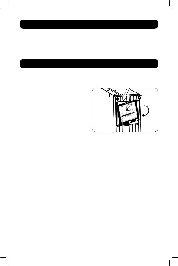
WARNING: When mounting the UPS system in a tower or wall-mount orientation, make sure the LCD Screen panel is at the top of the UPS, not at the bottom.
Note: To mount the UPS in an upright (tower) position, 2-9USTAND is required (sold separately).
Rotate the LCD Screen panel for easy viewing while the UPS is tower mounted. Insert a small screwdriver, or other tool, in the slots on either side of the panel. Pop the panel out, rotate it and pop the panel back in place.
5
201205048 93-3149.indb 5 |
6/19/2012 11:33:32 AM |
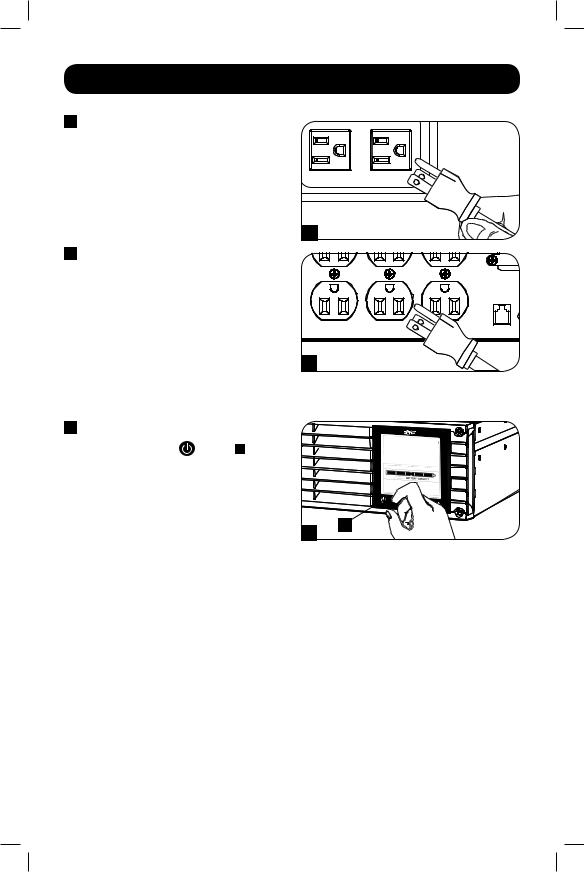
Quick Installation
1Plug the UPS into an outlet on a dedicated circuit.
|
Note: After you plug the UPS into a live AC |
|
|
|
outlet, the UPS (in “Standby” mode) will |
|
|
|
automatically charge its batteries, but will |
|
|
|
not supply power to its outlets until it is |
|
|
|
turned ON. |
|
|
|
|
|
1 |
2 |
Plug your equipment into |
|
|
|
the UPS.* |
|
|
|
* Your UPS is designed to support only electronic |
|
|
|
equipment. You will overload the UPS if the total |
|
|
|
VA ratings for all the equipment you connect |
|
|
|
exceeds the UPS’s Output Capacity. To find your |
|
|
|
equipment’s VA ratings, look on its nameplates. |
|
|
|
If the equipment is listed in amps, multiply the |
|
|
|
number of amps by 120 to determine VA. |
2 |
|
|
(Example: 1 amp × 120 = 120 VA) If you are |
||
|
unsure if you have overloaded the UPS’s outlets, |
|
|
|
see LOAD icon description in LCD Interface |
|
|
|
section under Basic Operation. |
|
|
3 |
Turn the UPS ON. |
|
|
|
Press and hold the |
button A for one |
|
|
second. The alarm will beep once briefly. |
|
|
Note: UPS system will function properly upon initial startup, however, maximum runtime for the unit’s battery will only be accessible after it has been charged for 24 hours.
3
6
A
201205048 93-3149.indb 6 |
6/19/2012 11:33:34 AM |

Optional Installation
These connections are optional. Your UPS will function properly without these connections.
1USB and RS-232 Serial Communications
Use the included USB cable (see 1A) or DB9 serial cable (see 1B) to connect the communication port on your computer to the communication port of your UPS. Install on your computer the Tripp Lite PowerAlert Software appropriate to your computer’s operating system.
2 EPO Port Connection
This optional feature is only for those applications which require connection to a facility’s Emergency Power Off (EPO) circuit. When the UPS is connected to this circuit, it enables emergency shutdown of the UPS’s inverter.
Using the cable provided, connect the EPO port of your UPS (see 2A) to a user-supplied normally closed or normally open switch according to the circuit diagram (see 2B).
The EPO port is not a phone line surge suppressor; do not connect a phone line to this port.
RS232 |
USB |
1A
RS232 |
USB |
1B |
RS232 |
USB |
2A
4-5 |
2B
7
201205048 93-3149.indb 7 |
6/19/2012 11:33:36 AM |
Optional Installation |
continued |
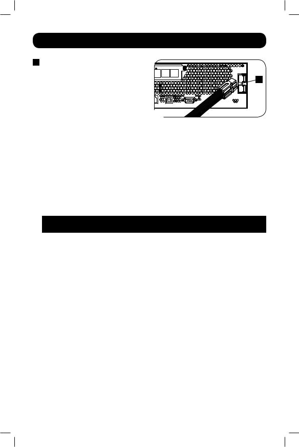
3External Battery Connection (Select Models)
Your UPS |
comes |
with a |
robust |
internal |
A |
|
battery |
system; |
external |
batteries are |
|
||
needed only to extend runtime. Adding |
|
|||||
external batteries will increase recharge time |
|
|||||
as well |
as |
runtime. This |
UPS |
supports |
|
|
BP24V15RT2U (limit 1), BP24V28-2U (limit |
3 |
|
|
|
||
1) and BP24V70-3U |
(multi-pack). |
|
|
|
|
|
The illustration (see |
|
) shows the location of your UPS’s External Battery Connector |
|
where |
||
3 |
A |
|||||
|
|
|||||
you will insert the battery pack cable. Complete installation instructions for your battery pack appear in the battery pack owner’s manual. Make sure that cables are fully inserted into their connectors. Small sparks may result during battery connection; this is normal.
Do not connect or disconnect battery packs when the UPS is running on battery power.
CAUTION! When an external battery pack is connected, make sure the AC load does not exceed the nameplate rating. Select models are derated when an external battery pack is connected. See UPS nameplate label for derating details.
When connecting external batteries to the UPS, go to the Tripp Lite website at www.tripplite. com/en/support/bpcon g/index.cfm to download the External Battery Pack Utility software to con gure your UPS for external battery support.
|
Wattage with Internal |
Wattage with External |
Model Name |
Batteries Only |
Batteries Attached |
|
|
|
SMART1000RM2U |
800W |
N/A |
|
|
|
SMART750RMXL2U |
600W |
450W |
|
|
|
Note:
1.The runtime will automatically recalculate once the External Battery Pack Tool process is complete.
2.If the setup will no longer include external batteries, the UPS can be con gured to work without external batteries via the LCD Screen. See External Battery Settings Control section under Basic Operation for details.
3.If external battery packs are removed, the UPS must be reset to “NO EXTERNAL BATTERY” via the LCD interface or the External Battery Con guration Program available on the Tripp Lite website. Failure to do so may result in damage to the internal batteries due to over-charging.
8
201205048 93-3149.indb 8 |
6/19/2012 11:33:37 AM |
Basic Operation
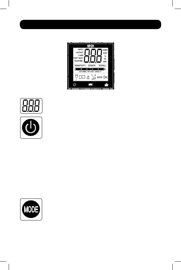
LCD Interface
 Note: This LCD image is shown with all icons illuminated. Under normal conditions, only select
  icons will be lit.
3-Digit Display: This display is generally used to show values for a given “Display” or “Control” screen.
“ON/OFF” Button
•To turn the UPS ON: After you plug the UPS into a live AC outlet, the UPS (in
“Standby” mode) will automatically charge its batteries, but will not supply power to its outlets until it is turned ON. With the UPS plugged into a live AC wall outlet, press and hold the “ON/OFF” button for one second.* The UPS will beep once to indicate ON status. Release the button.
•To cold-start the UPS: If utility power is absent, you can “cold-start” the UPS
(i.e., turn it on and supply power for a limited time from its batteries) by pressing and holding the “ON/OFF” button for one second.* The UPS will beep once to indicate ON status. Release the button.
•To turn the UPS OFF: With the UPS ON and receiving utility power, press and hold the “ON/OFF” button for 2.5 seconds.* The UPS will beep once to indicate OFF status. Then unplug the UPS from the wall outlet. The UPS will be completely off.
*If the user unintentionally presses the ON/OFF button, the OFF function can be temporarily canceled by continuing to hold the ON/OFF button until the UPS beeps and then, without releasing it, momentarily press either the MODE button or the ENTER/MUTE button. Once both buttons are released, the UPS will remain ON.
“MODE” Button
To enable viewing of power displays and control menu options, tap this button. See
“Display Power Conditions” & “Control Menu Options” for details.
•Can be used in conjunction with the ON/OFF button to cancel the “OFF” function. See “ON/OFF Button” instructions above.
•Can be used in conjunction with the ENTER/MUTE button to restore the LCD to Factory Mode. See “Control Menu Options.”
9
201205048 93-3149.indb 9 |
6/19/2012 11:33:38 AM |
Basic Operation continued
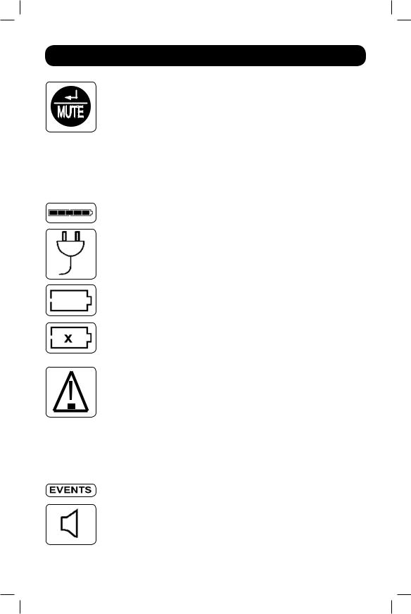
“ENTER/MUTE” Button
To toggle settings options while viewing a control menu option, tap this button.
The UPS power failure alarm can also be temporarily silenced by tapping this button. Once silenced, an alarm will automatically re-sound to indicate low battery conditions and can no longer be silenced.*
•Can be used in conjunction with the ON/OFF button to cancel the “OFF” function. See “ON/OFF Button” instructions above.
•Can be used in conjunction with the ENTER/MUTE button to restore the LCD to Factory Mode. See “ON/OFF Button” instructions.
Note: Alarm-free silent operation is available by setting the alarm to disable (see CONTROL MENU OPTIONS / ALARM ENABLE-DISABLE section).
Battery Capacity: This will be active in all “Display” modes, but is not shown in
“Control” modes.
AC Input: This indicates that the unit is running in Line Mode and supplying AC power to equipment connected to the output.
Battery Input: This will flash to indicate that the UPS is not receiving AC input and is running in inverter mode. The Battery Input icon is also used in conjunction with the EVENTS icon to indicate On Battery events.
Replace Battery Icon: In the event that UPS batteries expire and require replacement, this icon and the warning icon will flash. This icon will also flash after a failed UPS self-test (see the BASIC OPERATION / CONTROL MENU OPTIONS / SELF-TEST section for more information).
Warning: This will flash to let the user know that there is a warning condition and immediate action must be taken:
1.For Replace Battery: Replace Battery and Warning icons flash during any normal “Display” mode.
2.For Overload: Load, Warning and Load Percentage icons will flash, the alarm
will sound repeatedly and the LCD screen will switch from the user-selected display mode to Load Percentage. Overload indication is available in both AC and battery modes.
CAUTION! Any overload condition that is not correct by the user immediately may cause the UPS to shut down and cease supplying output power in the event of a blackout or brownout.
EVENTS Icon: Displayed in conjunction with the AVR icon and BATT icons to indicate the number of On Battery or AVR events that have occurred.
Alarm Off: Indicates that the alarm is disabled.
10
201205048 93-3149.indb 10 |
6/19/2012 11:33:39 AM |
Basic Operation continued
Alarm On: Indicates that the alarm is enabled.
INPUT Icon: Indicates that the 3-digit value displayed is the Input Voltage.
OUTPUT Icon: Indicates that the 3-digit value displayed is the Output Voltage.
LOAD Icon: Displayed in two modes:
1.Displayed in conjunction with the % icon and 3-digit value to indicate the load percentage.
2.Displayed in conjunction with KWH/Day and 3-digit value to indicate daily power consumption.
3.Both the LOAD icon and Warning icon will flash to indicate an overload.
BATT Icon: Displayed in two modes:
1.BATT icon (displayed in conjunction with % icon and 3-digit value) indicates the Battery Capacity %.
2.BATT icon is shown with TEST icon to indicate self-test mode or control mode.
% Icon: Indicates units of %.
TEST Icon: Displayed in conjunction with BATT icon to indicate that the UPS is performing a self-test.
RUNTIME Icon: Displayed in conjunction with the MIN icon and 3-digit value to indicate Runtime in minutes.
MIN Icon: Indicates units of minutes.
1.Displayed in conjunction with RUNTIME icon and 3-digit value to indicate battery runtime in minutes.
2.Displayed in conjunction with the 3-digit value (reporting “LCD”) to indicate the minimum brightness.
VWA Icon: This is a multipurpose icon which indicates units of Volts, VA, Watts, or Amps (V, VA, W, or A will be shown).
K Icon: Displayed in conjunction with the W to indicate Kilowatts. It is also used in conjunction with the WH and /DAY icons to indicate Kilowatt Hours per Day.
H and /DAY Icons: Displayed in conjunction with “K” and “W” icons to indicate Kilowatt Hours per day (KWH/DAY).
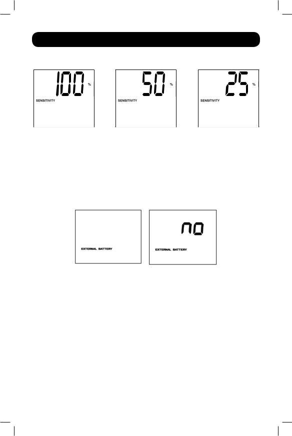
Sensitivity Icon: Displayed to set the AC input line sensitivity setting. Sensitivity settings available are 100% (Normal = no delay), 50% (half delay), and 25%
(full delay).
11
201205048 93-3149.indb 11 |
6/19/2012 11:33:39 AM |

Basic Operation |
continued |
SCROLL Icon: When enabled, the display will automatically cycle through each DISPLAY mode of the LCD once per two-second interval. If a button is pressed while Scroll Mode is enabled, the scroll function will pause for 10 seconds to allow the user to manually make menu selections before resuming scroll.
Automatic Voltage Regulation Icon: Indicates that the AC input is either low or high and that the AVR function is actively boosting or cutting the line. The AVR icon is also used in conjunction with the EVENTS icon to indicate AVR events.
EXTERNAL BATTERY Icon (Select Models): |
Displayed only when the EXTERNAL |
BATTERY SETTING CONTROL is active. |
|
BATTERY CAPACITY Icon: Used to better describe the battery capacity bar graph.
Display Power Conditions
Use the  button to advance through power conditions.
1. Voltage In |
2. Voltage Out |
|
|
3. Estimated Runtime |
4. Load % |
||
|
|
|
|
|
|
(in minutes) |
|
|
|
|
|
|
|
|
|
|
|
|
|
|
|
|
|
|
|
|
|
|
|
|
|
5. Load Wattage* |
6. KWH/Day** |
7. Battery Capacity % |
*Load Wattage is displayed in watts up to “999” and then will be displayed in Kilowatts.
**The Kilowatt Hour usage per day reports daily power consumption of equipment connected to the UPS in KWH
in a 24-hour cycle. Press and hold the |
button for 4 seconds to reset the accumulator to “0.” |
Note: When the UPS is in Battery Mode (power is supplied to the output from the batteries), the BATTERY icon will be lit in the display instead of the AC INPUT icon. The values displayed are random values used for example reference.
12
201205048 93-3149.indb 12 |
6/19/2012 11:33:40 AM |

Basic Operation continued
Control Menu Options
Enable/Disable Alarm
Tap the  button repeatedly to advance to the LCD display featuring the
  icon. Press the
  button to select ON or OFF alarm mode settings. The last option displayed before navigating away from this menu option will be the selected setting.
Note: Disabling the alarm via this control menu option will silence the alarm under all conditions, including low battery conditions.
LCD Brightness
Tap the  button repeatedly to advance to the LCD Brightness display marked “LCD.” Press the
  button to select Medium Backlight (default), High Backlight or Dim Backlight. The last option displayed before navigating away from this menu option will be the selected setting.
Note: The default brightness is set at medium. Any time a button is pressed, the LCD will engage the high brightness setting. After 2 minutes of inactivity, the backlight will revert to the selected setting until a button is pressed.
Self-test
Tap the  button repeatedly to advance to the TEST BATT display. Press the
  button to initiate the test. The test will last approximately 10 seconds as the UPS switches to battery to test the capacity with a load. Upon completion of the test, the display will indicate PAS or BAD (pass or bad) for 20 seconds, and then return to the home screen. Connected equipment can remain on during the test. Do not unplug your UPS to test it; this will remove safe electrical grounding.
Note: If the self-test result is BAD, it may be due to the batteries not being charged for 24 hours. Fully charge the batteries and repeat the self-test. Please refer to the note under Step 3 on Page 6.
Scroll Control
This setting is normally set to “OFF.” Setting it to “ON” allows the user to select the option to automatically scroll each operating condition of the UPS (such as Input Voltage, Output Voltage and
Runtime) automatically.
Tap the  button repeatedly to advance to the Scroll display as shown above.
Press the  button to advance to the next available option. The last option displayed, before navigating away from this menu option, will be the selected setting.
Note:
1.Each condition is displayed in 2-second intervals.
2.If a button is pressed while Scroll Mode is enabled, the scroll function will pause for 10 seconds to allow the user to manually make menu selections.
13
201205048 93-3149.indb 13 |
6/19/2012 11:33:40 AM |
Basic Operation continued
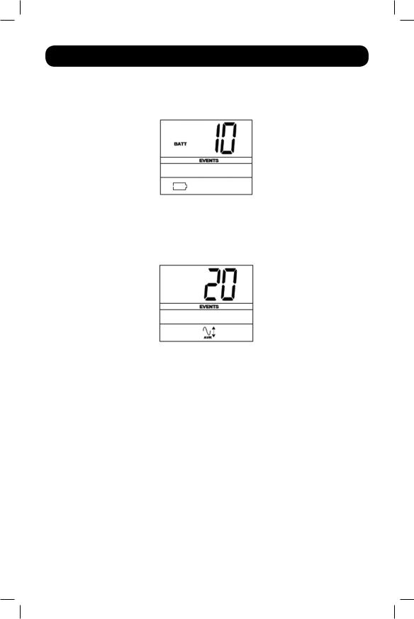
ON Battery Events
This feature allows the user to view the number of times the UPS has experienced an ON Battery
Event. To reset the counter to “0,” press and hold the  button.
Tap the  button repeatedly to advance to the ON Battery Events display, as shown above.
Note: The value displayed is a random value used for example reference.
AVR Events
This feature allows the user to view the number of times the UPS has experienced an Automatic Voltage Regulation Event. To reset the counter to “0,” press and hold the  button.
Tap the  button repeatedly to advance to the AVR display, as shown above.
Note: The value displayed is a random value used for example reference.
Power Sensitivity
This setting is normally set to 100%, which enables the UPS to protect against waveform distortions in its AC input. When such distortion occurs, the UPS will normally switch to providing pure sine wave power from its battery reserves for as long as the distortion is present. In some areas with poor utility power or where the UPS’s input power comes from a backup generator, frequent brownouts and/or chronic waveform distortion could cause the UPS to switch to battery too often, draining its battery reserves. You may be able to reduce how often your UPS switches to battery due to waveform distortion or brownouts by experimenting with different settings. As the setting is reduced, the UPS becomes more tolerant of variations in its input power’s AC waveform.
Note: When experimenting with different settings, operate connected equipment in a safe test mode so that the effect on the equipment of any waveform distortions in the UPS’s output can be evaluated without disrupting critical operations. The experiment should last long enough to assure that all expected line conditions are encountered.
14
201205048 93-3149.indb 14 |
6/19/2012 11:33:41 AM |
Basic Operation continued
Tap the  button repeatedly to advance to Sensitivity display, as shown on the previous page.
Press the  button to advance through the options. The last option displayed, before navigating away from this menu option, will be the selected setting.
External Battery Setting Control (Select Models)
This control menu option only appears when the UPS is configured using the External Battery Utility software and is reporting “YES” in the External Battery LCD Control Screen. This setting is normally set to “YES.” The only available LCD interface configuration option is to change the setting from “YES” to “NO” external batteries.
Note: See the Optional Installation section for information on configuring the UPS for external battery operation using the External Battery Utility software.
Tap the  button repeatedly to advance to the External Battery display, as shown above.
YES
To set the UPS to “NO” External Battery, press and hold the  button for 3.5 seconds.
Note: The Battery Runtime calculation is based on this setting. The runtime will automatically recalculate once the external battery setting is configured for “NO” external batteries.
Factory Mode Reset
The LCD settings can be restored to Factory Mode by holding the MODE and ENTER/MUTE buttons simultaneously for 5 seconds while in any display mode.
CAUTION: This action cannot be undone. The user must reconfigure the UPS for external batteries if the UPS’s setup includes external batteries.
15
201205048 93-3149.indb 15 |
6/19/2012 11:33:41 AM |

Basic Operation |
continued |
Other UPS
15A 120V NEMA 5-15R
Features (Rear Panel)
AC Outlets: All models include NEMA 5-15R outlets. These outlets provide your connected equipment with AC line power during normal operation and battery power during blackouts and brownouts. The UPS protects equipment connected to these outlets against damaging surges and line noise. If you have a serial or USB connection to your UPS, you can remotely reboot connected equipment by turning the outlets OFF and ON using Tripp Lite’s PowerAlert Software. The outlets are divided into one or more load banks (labelled “LOAD 1,” etc.) which may be remotely switched OFF and ON without interrupting power to equipment connected to the other outlets. Outlets labelled “UNSWITCHED” may not be remotely switched o .
Communications Ports (USB or RS-232): These ports connect your UPS to any workstation or server. Use with Tripp Lite’s PowerAlert Software and included cables to enable your computer to automatically save open les and shut down equipment during a blackout. Also use PowerAlert Software to monitor a wide variety of AC line power and UPS operating conditions. Consult your PowerAlert Software manual or contact Tripp Lite Customer Support for more information. See “USB and RS-232 Serial Communications” in the “Optional Installation” section for installation instructions.
EPO (Emergency Power O ) Port: Your UPS features a EPO port that may be used to connect the UPS to a contact closure switch to enable emergency inverter shutdown. See Optional Installation.
Accessory Slot: Remove the small cover panel from this slot to install optional accessories to remotely monitor and control your UPS. Refer to your accessory’s manual for installation instructions. Contact Tripp Lite Customer Support at (773) 869-1234 for more information, including a list of available SNMP, network management and connectivity products.
External Battery Connector (optional on select models): |
Use |
to connect |
Tripp Lite external battery packs for additional runtime. Refer |
to |
instructions |
available with the battery pack for complete connection information and safety warnings. Visit www.tripplite.com/support/battery/index.cfmto locate the supported battery type(s) for your UPS.
Input Breaker: Your UPS features one breaker that protects your UPS. If the breaker trips, remove some of the load on the circuit, then reset it by pressing the breaker switch in.
Ground Screw: Use this to connect any equipment that requires a chassis ground.
16
201205048 93-3149.indb 16 |
6/19/2012 11:33:42 AM |

Storage and Service
Storage
Before storing your UPS, turn it completely OFF: with the UPS ON and receiving utility power, press and hold the “ON/OFF” button for two seconds (an alarm will beep once briefly after the interval has passed); then, unplug the UPS from the wall outlet. If you store your UPS for an extended period of time, recharge the UPS batteries once every three months: plug the UPS into a wall outlet; allow it to charge for 12 hours; and then unplug it and place it back in storage. If you leave your UPS batteries discharged for an extended period of time, they will suffer a permanent loss of capacity.
Service
A variety of Extended Warranty and On-Site Service Programs are also available from Tripp Lite. For more information on service, visit www.tripplite.com/support. Before returning your product for service, follow these steps:
1.Review the installation and operation procedures in this manual to insure that the service problem does not originate from a misreading of the instructions.
2.If the problem continues, do not contact or return the product to the dealer. Instead, visit www.tripplite.com/support.
3.If the problem requires service, visit www.tripplite.com/support and click the Product Returns link. From here you can request a Returned Material Authorization (RMA) number, which is required for service. This simple online form will ask for your unit’s model and serial numbers, along with other general purchaser information. The RMA number, along with shipping instructions, will be e-mailed to you. Any damages (direct, indirect, special or consequential) to the product incurred during shipment to Tripp Lite or an authorized Tripp Lite service center is not covered under warranty. Products shipped to Tripp Lite or an authorized Tripp Lite service center must have transportation charges prepaid. Mark the RMA number on the outside of the package. If the product is within its warranty period, enclose a copy of your sales receipt. Return the product for service using an insured carrier to the address given to you when you request the RMA.
17
201205048 93-3149.indb 17 |
6/19/2012 11:33:42 AM |

Battery Replacement
Under normal conditions, the original batteries in your UPS will last many years. See Safety section before replacing batteries. The batteries are designed for hot-swap replacement (i.e., leaving the UPS in ON mode), but some qualified service personnel may wish to put the UPS in the OFF mode and disconnect equipment before proceeding.
Note: Refer to the label on the battery retention plate for the R.B.C. part number.
SMART750RMXL2U and SMART1000RM2U Battery (RBC24VLCD)
Replacement Procedure
|
Remove Front Panel |
3 |
|
|
1 |
Disconnect Batteries |
|||
|
||||
|
|
1 |
4 x screws |
3 |
|
2 |
Remove Battery Retention Plate |
4 |
Remove/Recycle Batteries |
2 4 x screws |
4 |
18
201205048 93-3149.indb 18 |
6/19/2012 11:33:45 AM |
 Loading...