


WARRANTY |
|
for |
Lite |
Owner’s Manual |
||||
REGISTRATION |
.com/warranty |
|||||||
|
on a |
|||||||
|
|
|
todayTripp |
|
|
|
|
|
|
|
-line |
|
|
|
|
|
|
Register |
|
FREE |
|
|
|
|
||
.tripplite |
|
|
|
|
||||
|
to |
win |
|
|
|
|
|
|
chance |
|
|
|
|
|
|
|
|
a |
www |
|
|
PowerVerter |
|
|||
|
|
|
|
|
|
|
® |
|
product! |
|
|
|
|
|
Series (v. 3.0) |
|
|
|
|
|
|
|
|
|
||
DC-to-AC Inverter/Chargers |
1111 W. 35th Street, Chicago, IL 60609 USA |
|||||||
|
|
|
|
|
|
Input |
Output |
|
|
|
|
|
|
|
Customer Support: (773) 869-1234 |
||
|
|
Invert: |
|
|
12 VDC |
120V, 60 Hz. AC |
||
|
|
|
|
www.tripplite.com |
||||
|
|
Charge: |
|
120V, 60 Hz. AC |
12 VDC |
|
||
Quiet Mobile Power
Congratulations! You've purchased the most advanced, feature-rich Inverter/Charger designed for recreational applications. Tripp Lite RV Inverter/Chargers are the quiet alternative to generators-with no fumes, fuel or noise to deal with! You get AC electricity anywhere and anytime you need it: away from shore power, rolling down the highway, dry camping in majestic back country or overnighting at a non-electric site. Your Tripp Lite Inverter/Charger provides your appliances, equipment and electronics with utilityor generator-supplied AC electricity (filtered through premium ISOBAR® surge protection) whenever available. In addition, it automatically powers your craft's 12V system and recharges your connected battery bank-doing what traditional converter/chargers do. Whenever power blackouts, brownouts or high voltages occur, your Inverter/Charger immediately and automatically switches over to inverting battery output to power connected AC equipment.
Better for Your Equipment
Premium Protection Levels
•Built-In ISOBAR® Surge Protection
•Automatic Overload Protection
Ideal Output for All Loads (including computers)
•Frequency-Controlled Output
•Fast Load Switching
•Balanced Load Sharing*
Better for Your Batteries
Faster Battery Recharge
• High-Amp, 3-Stage Battery Charger (adjustable)
Critical Battery Protection
•Battery Charge Conserver (Load Sense)*
•Battery Temperature Sensing*
•High-Efficiency DC-to-AC Inversion
Better for You
Quiet, Simple, Maintenance-Free Operation
•Multi-Function Lights & Switches
•Automatic Generator Starting*
•Moisture-Resistant Construction†
Contents
Specifications/Warranty/Warranty Registration |
2 |
Safety |
3 |
Feature Identification |
4 |
Operation |
5-6 |
Configuration |
6-8 |
Battery Selection |
9 |
Mounting |
10 |
Battery Connection |
11 |
AC Input/Output Connection |
12 |
Service/Maintenance |
13 |
Troubleshooting |
13 |
Français |
14 |
* Available on all models except 612 models. †Inverter/Chargers are moisture-resistant, not waterproof. Copyright © 2005. PowerVerter® is a registered trademark of Tripp Lite. All rights reserved.
2R
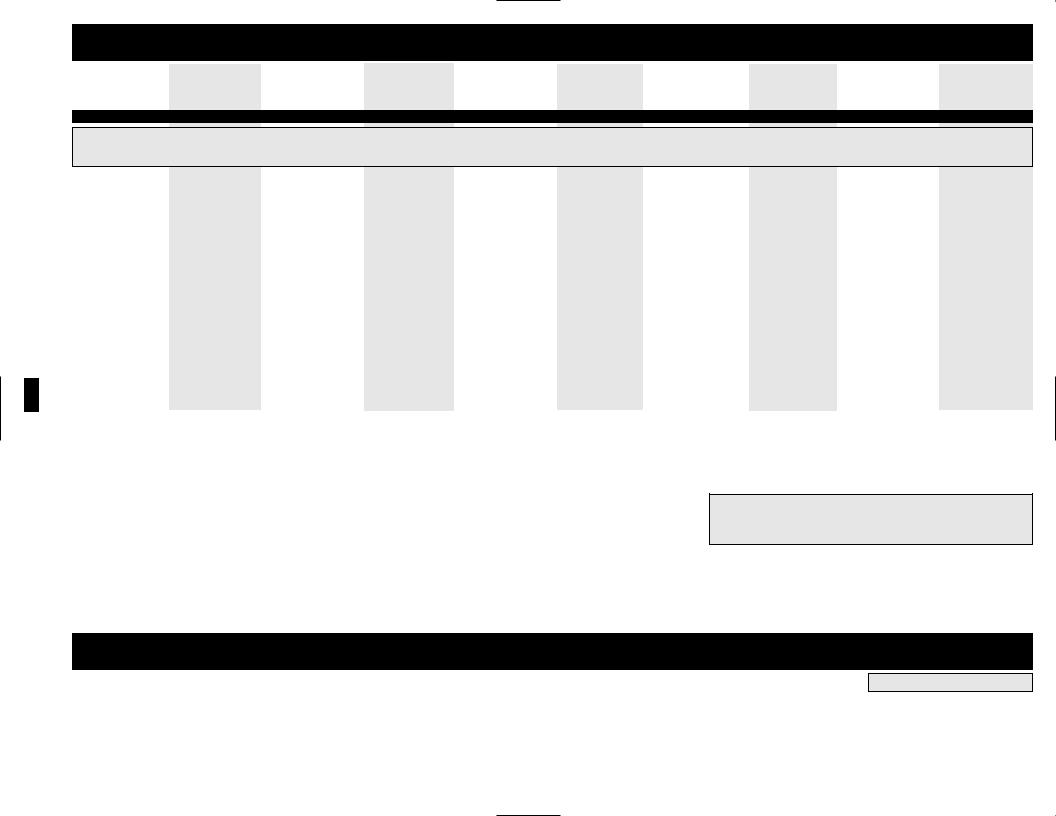
Specifications
MODEL NUMBER: |
RV612UL |
RV612ULH |
RV1012UL |
RV1012ULHW |
RV1512UL |
RV2012UL |
RV2012OEM |
RV2512OEM |
RV3012OEM |
Series Number: |
AGAP60012MVJ |
AGAP60012MVJ |
AGAP100012MV3 |
AGAP100012MV3 |
AGAP200012MV3 |
AGAP200012MV3 |
AGAP200012MVP3 |
|
AGAP4669 |
Agency Approvals: |
UL458 |
UL458 |
UL458 with Marine Sup. |
UL458 |
UL458 |
UL458 with Marine Sup. |
UL458 |
None |
UL458 |
AC Input Connection: |
Input Cord |
Hardwire |
Input Cord |
Hardwire |
Hardwire |
Hardwire |
Hardwire |
Hardwire |
Hardwire |
INVERTER
Common Specifications for All Models: • DC Input Volts (Nominal):12 VDC • · DC Input Voltage Range:10 - 15 VDC • Output Volts (Nominal):120 VAC, ± 5% • Output Frequency (Nominal):60 Hz, ± 0.5% • Efficiency:88% to 94%, depending on load and temperature
Select Tripp Lite Inverter/Chargers include a Battery Charge Conserver (Load Sense) Control which saves battery power by allowing users to set the minimum load level at which the unit’s inverter turns on. Users can significantly reduce the No Load DC Input Current (approximately 1 to 3 A for all models) to a very low amp level with the use of this control.
|
Continuous Power (@ 20 C): |
600 |
600 |
1000 |
1000 |
1500 |
2000 |
2000 |
2500 |
3000 |
|
OverPower™ Peak Surge Power:* |
900 |
900 |
1500 |
1500 |
2250 |
3000 |
3000 |
3750 |
4500 |
|
Double Boost™ Peak Surge Power:* |
1200 |
1200 |
2000 |
2000 |
3000 |
4000 |
4000 |
5000 |
6000 |
|
Maximum Output AC Current |
5 A |
5 A |
8.3 A |
8.3 A |
12.5 A |
16.7 A |
16.7 A |
20 A |
25 A |
|
(Continuous): |
|
|
|
|
|
|
|
|
|
|
UL Required DC Fuse |
TPN-80 (fuse) |
TPN-80 (fuse) |
ANL-200 (fuse) |
ANL-200 (fuse) |
ANL-275 |
two ANL-200 (fuse) |
two ANL-200 (fuses) |
two ANL-200 (fuses) |
two ANL-275 (fuses) |
|
and Fuse Block: |
R25100-1CR (fuse block) |
R25100-1CR (fuse block) |
4164 (fuse block) |
4164 (fuse block) |
4164 (fuse block) |
4164 (fuse block) |
two 4164 (fuse blocks) |
two 4164 (fuse blocks) |
two 4164 (fuse blocks) |
|
(or equivalent) |
Bussmann |
Bussmann |
Bussmann |
Busmann |
Bussmann |
Bussmann |
Bussmann |
Bussmann |
Bussmann |
|
|
(manufacturer) |
(manufacturer) |
(manufacturer) |
(manufacturer) |
(manufacturer) |
(manufacturer) |
(manufacturer) |
(manufacturer) |
(manufacturer) |
|
DC Input Current @ |
|
|
|
|
|
|
|
|
|
|
Nominal V DC Full Load: |
56 A |
56 A |
95 A |
95 A |
145 A |
190 A |
190 A |
240 A |
290 A |
|
|
|
|
|
|
|
|
|
|
|
|
BATTERY CHARGER |
|
|
|
|
|
|
|
|
|
|
|
|
|
|
|
|
|
|
|
|
|
Common Specifications for All Models • Acceptance Volts VDC:Selectable 14.4 V** / 14.2 V Wet** / Gel • Float Volts DC (w/gel):13.3 V (13.6 V) • · Input Volts (Nominal):120 VAC |
|
|
|
|
|||||
|
Charging Capacity DC: |
45 A / 11 A** |
45 A** / 11 A |
55 A** / 14 A |
55 A** / 14 A |
75 A** / 19 A |
100 A** / 25 A |
100 A** / 25 A |
120 A** / 30 A |
140 A** / 35 A |
|
Input Current AC: |
9.5 A |
9.5 A |
11.5 A |
11.5 A |
15 A |
20 A |
20 A |
24 A |
30 A |
|
|
|
|
|
|
|
|
|
|
|
|
LINE VAC OPERATION |
|
|
|
|
|
|
|
|
|
|
|
|
|
|
|
|
|
|
|
|
|
Common Specifications for All Models • Input Frequency (Nominal):60 Hz, ±10% • Maximum Input Volts (Transfer to Battery) (Continuous, Charger at Maximum):Selectable 135** or 145 VAC |
|
|
|
|
|||||
|
Minimum Input Volts: |
Selectable 95** or |
Selectable 95** or |
Selectable 75**, 85, |
Selectable 75**, 85, |
Selectable 75**, 85, |
Selectable 75**, 85, |
Selectable 75**, 85, |
Selectable 75**, 85, |
Selectable 75**, 85, |
|
(Transfer to Battery) |
105 VAC |
105 VAC |
95 or 105 VAC |
95 or 105 VAC |
95 or 105 VAC |
95 or 105 VAC |
95 or 105 VAC |
95 or 105 VAC |
95 or 105 VAC |
|
Maximum Input AC Current |
11.3 A |
14.5 A |
12 A |
20 A |
35 A |
38 A |
40 A |
44 A |
37 A |
|
(Continuous, Charger |
|
|
|
|
|
|
|
|
|
|
at Maximum): |
|
|
|
|
|
|
|
|
|
|
Maximum Bypass AC Current: |
6 A |
6 A |
12 A |
12 A |
20 A |
20 A |
20/20 A |
20/20 A |
20/20 A |
|
(Load circuit breaker limited) |
|
|
|
|
|
|
|
|
|
* OverPower duration (up to 1 hour). DoubleBoost duration (up to 10 seconds). Actual duration depends on battery age, battery charge level and ambient temperature. **Factory setting. The policy of Tripp Lite is one of continuous improvement. Specifications are subject to change without notice. This product designed and engineered in the USA.
Minimum Recommended Cable Sizing Chart†
Use in conjunction with DC wiring connection instructions in the Battery Connection section.
Inverter/Charger DC Volt: 12
|
|
|
|
|
|
Wire Gauge |
|
||
|
|
|
|
|
|
|
|
|
|
|
|
|
|
|
|
|
|
|
Twin 00 (2/0) |
|
Watts |
6 |
4 |
2 |
0 |
|
00 (2/0) |
|
(RV2012OEM, RV2512OEM & RV3012OEM only) |
500 |
15 ft |
25 ft |
39 ft |
62 ft |
|
79 ft |
|
158 ft. |
|
|
|
|
|
|
|
|
|
|
|
700 |
11 ft |
18 ft |
28 ft |
44 ft |
|
56 ft |
|
112 ft. |
|
|
|
|
|
|
|
|
|
|
|
1000 |
N/R |
12 ft |
20 ft |
31 ft |
|
39 ft |
|
78 ft. |
|
|
|
|
|
|
|
|
|
|
|
2000 |
N/R |
N/R |
N/R |
16 ft |
|
20 ft |
|
40 ft. |
|
|
|
|
|
|
|
|
|
|
|
2400 |
N/R |
N/R |
N/R |
13 ft |
|
16 ft |
|
32 ft. |
|
|
|
|
|
|
|
|
|
|
|
3000 |
N/R |
N/R |
N/R |
10 ft |
|
13 ft |
|
26 ft. |
|
|
|
|
|
|
|
|
|
|
|
† N/R = Not Recommended. NOTE: Acceptable power is directly related to cable length (i.e. - the shorter the cable, the better the performance)
Note on Labeling Two symbols are used on the RV labels.
V~: AC Voltage V 
 : DC Voltage
Limited Warranty
Tripp Lite warrants its Inverter/Chargers to be free from defects in materials and workmanship for a 30 month period from the date of retail purchase by end user.
Tripp Lite’s obligation under this warranty is limited to repairing or replacing (at its sole option) any such defective products. To obtain service under this warranty you must obtain a Returned Material Authorization (RMA) number from Tripp Lite or an authorized Tripp Lite service center. Products must be returned to Tripp Lite or an authorized Tripp Lite service center with transportation charges prepaid and must be accompanied by a brief description of the problem encountered and proof of date and place of purchase. This warranty does not apply to equipment which has been damaged by accident, negligence or misapplication or has been altered or modified in any way, including opening of the unit’s casing for any reason. This warranty applies only to the original purchaser who must have properly registered the product within 10 days of retail purchase.
EXCEPT AS PROVIDED HEREIN, TRIPP LITE MAKES NO WARRANTIES, EXPRESS OR IMPLIED, INCLUDING WARRANTIES OF MERCHANTABILITY AND FITNESS FOR A PARTICULAR PURPOSE. Some states do not permit limitation or exclusion of implied warranties; therefore, the aforesaid limitation(s) or exclusion(s) may not apply to the purchaser.
EXCEPT AS PROVIDED ABOVE, IN NO EVENT WILL TRIPP LITE BE LIABLE FOR DIRECT, INDIRECT, SPECIAL, INCIDENTAL OR CONSEQUENTIAL DAMAGES ARISING OUT OF THE USE OF THIS PRODUCT, EVEN IF ADVISED OF THE POSSIBILITY OF SUCH DAMAGE. Specifically, Tripp Lite is not liable for any costs, such as lost profits or revenue, loss of equipment, loss of use of equipment, loss of software, loss of data, costs of substitutes, claims by third parties, or otherwise.
Tripp Lite has a policy of continuous improvement. Specifications are subject to change without notice.
WARRANTY REGISTRATION
Visit www.tripplite.com/warranty to register the warranty of your new
Tripp Lite product. You'll be automatically entered into a drawing for a chance to win a FREE Tripp Lite product!*
* No purchase necessary. Void where prohibited. Some restrictions apply. See website for details.

Important Safety Instructions
SAVE THESE INSTRUCTIONS!
This manual contains important instructions and warnings that should be followed during the installation, operation and storage of all Tripp Lite Inverter/Chargers.
Note: For Marine installations, please replace this page with the page titled "For Marine Applications Only" found in the Owner's Manual Addendum.
Location Warnings
•Although your Inverter/Charger is moisture resistant, it is NOT waterproof. Flooding the unit with water will cause it to short circuit and could cause personal injury due to electric shock. Never immerse the unit, and avoid any area where standing water might accumulate. Mounting should be in the driest location available.
•Leave a minimum of 2" clearance at front and back of the Inverter/Charger for proper ventilation. To avoid automatic Inverter/Charger shutdown due to overtemperature, any compartment that contains the Inverter/Charger must be properly ventilated with adequate outside air flow. The heavier the load of connected equipment, the more heat will be generated by the unit.
•Do not install the Inverter/Charger directly near magnetic storage media, as this may result in data corruption.
•Do not install near flammable materials, fuel or chemicals.
Battery Connection Warnings
•The Inverter/Charger will not operate (with or without utility power) until batteries are connected.
•Multiple battery systems must be comprised of batteries of identical voltage, age, amp-hour capacity and type.
•Because explosive hydrogen gas can accumulate near batteries if they are not kept well ventilated, your batteries should not be installed (whether for a mobile or stationary application) in a “dead air” compartment. Ideally, any compartment would have some ventilation to outside air.
•Sparks may result during final battery connection. Always observe proper polarity as batteries are connected.
•Do not allow objects to contact the two DC input terminals. Do not short or bridge these terminals together. Serious personal injury or property damage could result.
Equipment Connection Warnings
Do not use a Tripp Lite RV Inverter/Charger in life support or healthcare applications where a malfunction or failure of a Tripp Lite RV Inverter/Charger could cause failure of, or significantly alter the performance of, a life support device or medical equipment.
•You may experience uneven performance results if you connect a surge suppressor, line conditioner or UPS system to the output of the Inverter/Charger.
•Corded Models: Do not modify the Inverter/Charger’s plug or receptacle in a way that eliminates its ground connection. Do not use power adapters that will eliminate the plug’s ground connection.
•Connect your Inverter/Charger only to a properly grounded AC power outlet or hardwired source. Do not plug the unit into itself; this will damage the device and void your warranty.
Operation Warnings
•Your Inverter/Charger does not require routine maintenance. Do not open the device for any reason. There are no user serviceable parts inside.
•Potentially lethal voltages exist within the Inverter/Charger as long as the battery supply and/or AC input are connected. During any service work, the battery supply and AC input connection (if any) should therefore be disconnected.
•Do not connect or disconnect batteries while the Inverter/Charger is operating in either inverting or charging mode. Operating Mode Switch should be in the OFF position. Dangerous arcing may result.
3R

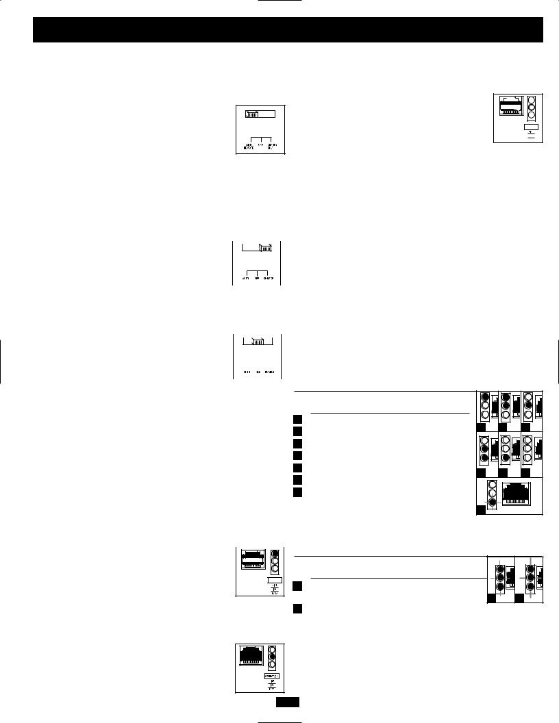
Feature Identification
Identify the premium features on your specific model and quickly locate instructions on how to maximize their use.
1 Configuration DIP Switches: optimize Inverter/Charger operation depending on your application. See Configuration section for setting instructions.
2Operating Mode Switch: controls Inverter/Charger operation. The “AUTO/REMOTE” setting ensures your equipment receives constant, uninterrupted AC power. It also enables the Inverter/Charger to be remotely monitored and controlled with an optional remote module (Tripp Lite model APSRM4, sold separately or included with select models). The “CHARGE ONLY” setting allows your batteries to return to full charge faster by turning the inverter off which halts battery discharging. See Operation section for setting instructions.
3“LINE”, “INVERT”, “LOAD” LEDs: intuitive “traffic light” signals show whether the Inverter/Charger is operating from AC line power or DC battery power. It also warns you if the connected equipment load is too high. See Operation section for instructions on reading the indicator lights.
4“BATTVOLT/CHRGCURR” LEDs: these three lights will turn ON in several sequences to show two separate operational conditions depending on the position of the Operating Mode Switch. See Operation section for instructions on reading indicator lights.
5DC Power Terminals: connect to your battery terminals. See Battery Connection section for instructions.
6Ground Fault Interrupter (GFI) AC Receptacles (not on hardwire models): allow you to connect equipment that would normally be plugged into a utility outlet. They feature ground fault interrupter switches that trip if there is excessive current on the ground safety wire.
7AC Input Cord (not on hardwire models): connects the Inverter/Charger to any source of utilityor generator-supplied AC power. SeeAC Input/Output Connection section for instructions.
8 Hardwire AC Input/Output Terminals (not on corded models): securely connect the Inverter/Charger to vehicle or facility electrical system input and recommended GFI receptacle output. See AC Input/Output Connection section for instructions.
9Resettable Circuit Breaker: protect your Inverter/Charger against damage due to overload. See Operation section for resetting instructions.
10Remote Control Module Connector: allows remote monitoring and control with an optional module (Tripp Lite model APSRM4, sold separately or included with select models). See remote module owner’s manual for connection instructions.
11Battery Charge Conserver (Load Sense) Dial (not on 612 models): conserves battery power by setting the low-load level at which the Inverter/Charger’s inverter automatically shuts off. See Configuration section for setting instructions.
12Main Ground Lug: properly grounds the Inverter/Charger to vehicle grounding system or to earth ground. See Configuration section for instructions.
13Multi-Speed Cooling Fan: quiet, efficient fan prolongs equipment service life.
14Hardwire AC Input/Output Cover Plate
15Battery Temperature Sensing Connector (not on 612 models): prolongs battery life by adjusting charge based on battery temperature. Use with cable (included on select models). See Configuration section for details.
16Automatic Generator Start Connector (not on 612 models): automatically cycles generator based on battery voltage. Use with user-supplied cable. See Configuration section for details.
13 |
1* |
4 |
10 |
3 |
2 |
11† |
13 |
1 |
4 |
10 |
3 |
2 |
11 |
|
|
|
|
|
|
|
|
|
|||||||
|
|
|
|
|
|
|
15 |
Side Mounted, |
||||||
|
|
|
|
|
|
|
|
|
|
|
|
|
||
|
|
|
|
|
|
15† |
|
|
|
|
|
|
|
Not Shown |
|
|
|
|
|
|
Side Mounted, |
|
|
|
|
|
16 |
Side Mounted, |
|
|
|
|
|
|
|
|
Not Shown |
|
|
|
|
|
||
|
|
|
|
|
|
|
|
|
|
|
|
|
|
Not Shown |
|
|
|
16† Side Mounted, |
|
|
|
|
|
|
|
|
Not Shown |
|
“FOR USE WITH COPPER WIRE ONLY” |
9 |
||
|
|
|
9 |
|
HOT |
IN |
|
|
|
|
|
|
|
|
|||
|
|
|
|
NEUTRAL |
IN |
|
||
|
|
|
6 |
|
|
|||
|
|
|
|
GROUND |
IN |
|
||
|
|
|
|
|
GROUND |
OUT |
|
|
|
|
|
|
|
HOT |
OUT |
|
|
|
|
|
|
|
NEUTRAL |
OUT |
|
|
Front View (Corded Models) |
5 |
7 |
12** |
5 |
8 |
14 |
|
|
* 612 models have only one set of DIP Switches. ** Select models include front-mounted ground lug. † Available on all models except 612 models. |
Front View (Single Input/Output Hardwire Models) |
|
|
|
||||
13 |
1 |
4 |
10 |
3 |
2 |
11 |


 15
15
16 12

 9
9
 8
8
5
12
Front View (Dual Input/Output Hardwire Models) |
Rear View (Single Input/Output Hardwire Models and Select Corded Models) |
4R
Operation
Switch Modes
After configuring, mounting and connecting your Inverter/Charger, you are able to operate it by switching between the following operating modes as appropriate to your situation:
AUTO/REMOTE: Switch to this mode when you need constant, uninterrupted AC power for connected appliances and equipment. The Inverter/Charger will
continue to supply AC power to connected equipment and to charge your connected batteries while utilityor generator-supplied AC power is present. Since the
inverter is ON (but in Standby) in this mode, it will automatically switch to your battery system to supply AC power to connected equipment in the absence of a utility/generator source or in over/under voltage situations. “AUTO/REMOTE” also enables an optional remote control module (Tripp Lite model APSRM4, sold separately or included with select models) to function when connected to the unit.
CHARGE ONLY: Switch to this mode when you  are not using connected appliances and equipment in
order to conserve battery power by disabling the inverter. The Inverter/Charger will continue to supply AC power to connected equipment and charge 
connected batteries while utilityor generator-supplied AC power is present. However, since the inverter is OFF in this mode, it WILL NOT supply AC power to connected equipment in the absence of a utility/generator source or in over/under voltage situations.
OFF: Switch to this mode to shut down the  Inverter/Charger completely, preventing the inverter
from drawing power from the batteries, and preventing utility AC from passing through to connected  equipment or charging the batteries. Use this switch
to automatically reset the unit if it shuts down due to overload or overheating. First remove the excessive load or allow the unit to sufficiently cool (applicable to your situation). Switch to “OFF”, then back to “AUTO/REMOTE” or “CHARGE ONLY” as desired. If unit fails to reset, remove more load or allow unit to cool further and retry. Use an optional remote control module (Tripp Lite model APSRM4, sold separately or included with select models) to reset unit due to overload and overtemperature.
Indicator Lights
Your Inverter/Charger (as well as an optional Tripp Lite Remote Control Module, sold separately or included with select models) is equipped with a simple, intuitive, user-friendly set of indicator lights. These easily-remembered “traffic light” signals will allow you, shortly after first use, to tell at a glance a wide variety of operating details.
“LINE Green LED”: If the operating mode switch is  set to “AUTO/REMOTE”, this light will ILLUMI-
 NATE CONTINUOUSLY when your connected equipment is receiving continuous AC power sup-


plied from a utility/generator source.
If the operating mode switch is set to “CHARGE
ONLY”, this light will BLINK to alert you that the unit’s inverter is OFF and will NOT supply AC power in the absence of a utility/generator source or in over/under voltage situations.
“INV” (Inverting) Yellow LED: This light will ILLUMINATE CONTINUOUSLY whenever connected equipment is receiving battery-supplied, inverted AC power (in the absence of a utility/generator source or in over/under voltage situations). This
5R
light will be off when AC power is supplying the load. This light will BLINK to alert you if the load is less than the Battery Charge Conserver (Load Sense) setting.
“LOAD” Red LED: This red light will ILLUMI- 


 NATE CONTINUOUSLY whenever the inverter is
  functioning and the power demanded by connected
  appliances and equipment exceeds 100% of load


 capacity. The light will BLINK to alert you when the
 inverter shuts down due to a severe overload or overheating. If this happens, turn the operating mode switch “OFF”; remove the overload and let the unit cool. You may then turn the operating mode switch to either “AUTO/REMOTE” or “CHARGE ONLY” after it has adequately cooled. This light will be off when AC power is supplying the load.
“BATT VOLT/CHRG CURR” LEDs: these three lights will turn ON in several sequences to show two separate operational conditions depending on the position of the Operating Mode Switch.
If the switch is in the "AUTO/REMOTE" position, the LEDs indicate the approximate charge level and voltage of your connected battery bank and alert you to several fault conditions. See Chart for charge and voltage levels.
If the switch is in the "CHARGE ONLY" position, the LEDs indicate the approximate charge rate of the Inverter/Charger. See Chart for charge rates. Note: the charge rates in the chart are expressed as percentages of the Inverter/Charger's rated charging amps, which vary by model. Refer to the Specifications to determine the charging amps of your specific model.
LED Function with Switch in "AUTO/REMOTE" Position
Approximate Battery Charge Level* |
|
|
|
||
|
LEDs |
Battery Capacity |
|
|
|
|
Illuminated |
(Charging/Discharging) |
|
|
|
1 |
Green |
91%–Full |
1 |
|
|
2 |
Green & Yellow |
81%–90% |
2 |
3 |
|
|
|
|
|||
3 Yellow |
61%–80% |
4 |
Yellow & Red |
41%–60% |
|
|
5 |
Red |
21%–40% |
5 |
6 |
|
All three lights off |
4 |
||
6 |
1%–20% |
|
|
7 Flashing red |
0% (Inverter |
|
shutdown)** |
7
* Charge levels listed are approximate. Actual conditions vary
depending on battery condition and load. ** Inverter shutdown protects battery against damage due to excessive discharge.
Fault Condition |
|
|
|
|
|
LEDs |
Fault |
|
|
|
Illuminated |
Condition |
|
|
1 |
All three lights |
Excessive discharge |
|
|
|
flash slowly* |
(Inverter shutdown) |
1 |
2 |
2 |
All three lights |
Overcharge (Charger |
|
|
|
flash quickly** |
shutdown) |
|
|
*Approximately ½ second on, ½ second off. See Troubleshooting section. Inverter shutdown protects battery against damage due to excessive discharge.** Approximately ¼ second on, ¼ second off. Charger shutdown protects battery against damage due to overcharge. May also indicate a battery charger fault exists. See Troubleshooting section.
 Loading...