


|
|
|
|
|
|
|
|
chance |
|
|
|
|
|
|
for |
|
|
product! |
|
Warranty today |
Lite |
|
|||||||
Registrationonline |
.com/warranty |
||||||||
|
|
|
|
|
|
|
a |
|
|
|
|
|
FREE |
Tripp |
|
|
|
|
|
Registerwin |
|
|
|
|
|
|
|
||
a |
.tripplite |
|
|
|
|
||||
to |
www |
|
|
|
|
|
|
||
Owner’s Manual
PDUMH15ATNET
PDUMH20ATNET
Switched Rack PDU with Automatic Transfer Switch
Important Safety Instructions
Installation
Features
Configuration and Operation
Technical Support
Warranty and Warranty Registration
Español
Français
2
3
8
10
12
12
13
25
1111 W. 35th Street • Chicago, IL 60609 USA
(773) 869-1234 • www.tripplite.com
Copyright © 2007 Tripp Lite. All rights reserved. SmartOnline™ is a trademark of Tripp Lite.

Important Safety Instructions
SAVE THESE INSTRUCTIONS
This manual contains instructions and warnings that should be followed during the installation, operation, and storage of this product. Failure to heed these instructions and warnings will void the product warranty.
•The PDU provides convenient multiple outlets, but it DOES NOT provide surge or line noise protection for connected equipment.
•The PDU is designed for indoor use only in a controlled environment away from excess moisture, temperature extremes, conductive contaminants, dust or direct sunlight.
•Do not connect the PDU to an ungrounded outlet or to extension cords or adapters that eliminate the connection to ground.
•The power requirement for each piece of equipment connected to the PDU must not exceed the individual outlet’s load rating.
•The total power requirement for equipment connected to the PDU must not exceed the maximum load rating for the PDU.
•Do not drill into or attempt to open any part of the PDU housing. There are no user-serviceable parts inside.
•Do not attempt to modify the PDU, including the input plugs and power cables.
•Do not attempt to use the PDU if any part of it becomes damaged.
•Do not attempt to mount the PDU to an insecure or unstable surface.
•Never attempt to install electrical equipment during a thunderstorm.
•Use of this equipment in life support applications where failure of this equipment can reasonably be expected to cause the failure of the life support equipment or to significantly affect its safety or effectiveness is not recommended. Do not use this equipment in the presence of a flammable anesthetic mixture with air, oxygen or nitrous oxide.
2
Installation
Mounting the PDU
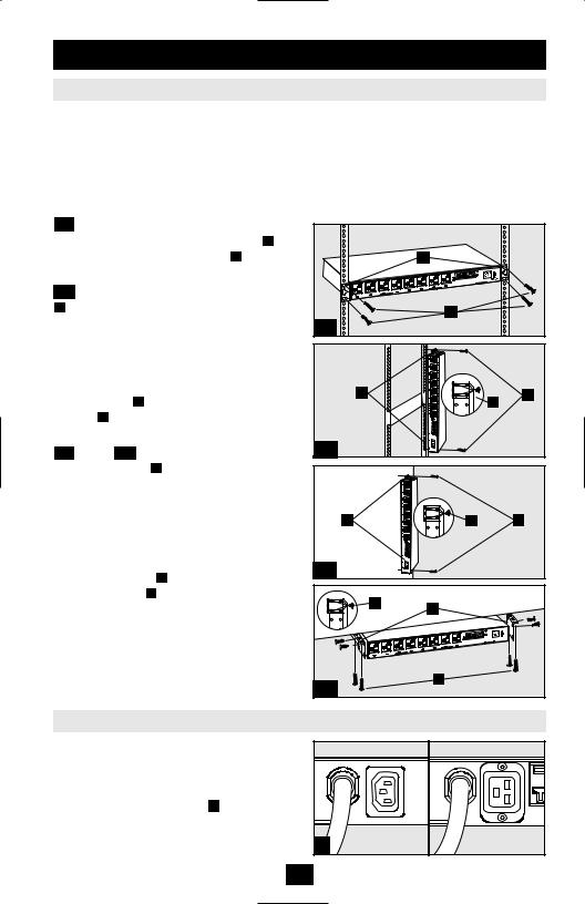
The PDU supports four primary mounting configurations: 1U Rack, 0U Rack, Wall and Under-Counter.
Note: Regardless of configuration, the user must determine the fitness of hardware and procedures before mounting. The PDU and included hardware are designed for common rack and rack enclosure types and may not be appropriate for all applications. Exact mounting configurations may vary.
1-1 1U Rack Mounting: Attach the PDU to the rack by inserting four user-supplied screws A through the PDU mounting brackets B and into the mounting holes of the rack rail as shown.
1-2 0U Rack Mounting: Remove the screws
C attaching the mounting brackets to the PDU, change the orientation of the brackets as shown and reattach the brackets. Use only the screws supplied by the manufacturer or their exact equivalent (#6-32, 1/4" flat head). Attach the PDU vertically by inserting two or more usersupplied screws A through the PDU mounting brackets B and into mounting points in the rack or rack enclosure.
1-3 Wall or 1-4 Under-Counter Mounting:
Remove the screws C attaching the mounting brackets to the PDU, change the orientation of the brackets as shown and reattach the brackets. Use only the screws supplied by the manufacturer or their exact equivalent (#6-32, 1/4" flat head). Attach the PDU to a stable mounting surface by inserting two or more user-supplied screws A through the PDU mounting brackets B and into secure points on the mounting surface.
Connecting the PDU
The PDU includes two AC power inputs: Primary and Secondary. The Primary input cord is permanently attached to the rear of the PDU. The Secondary input cord is detachable and
connects to the IEC power inlet 2 at the rear of the PDU (PDUMH15ATNET - IEC-320-C14 inlet; PDUMH20ATNET - IEC-320-C20 inlet).
|
B |
|
A |
1-1 |
|
B |
A |
|
C |
1-2 |
|
B |
|
C |
A |
1-3 |
|
|
|
|
C |
B |
|
|
|
|
A
1-4
2 |
PDUMH15ATNET |
PDUMH20ATNET |
3

Installation continued |
|
|
|
|
Connecting the PDU continued |
|
|
|
|
2-1 Connect Input Plug Adapters (Optional - |
|
|
|
|
Model PDUMH20ATNET Only): The PDU |
|
|
|
|
includes two adapters that convert one or both |
|
|
|
|
of the L5-20P input plugs to 5-20P input plugs. |
2-1 |
|
PDUMH20ATNET |
|
Connecting the adapters is optional. The PDU |
|
|||
|
|
|
||
will function normally without connecting the |
|
|
|
|
adapters. |
|
|
|
|
2-2 Connect Secondary Input Cord to PDU: |
|
|
|
|
Although the PDU will operate without |
|
|
|
|
connecting the Secondary input cord, the |
2-2 |
PDUMH15ATNET |
PDUMH20ATNET |
|
Secondary input is required for the PDU's |
||||
|
|
|
||
Automatic Transfer Switch function. |
|
|
|
|
2-3 Connect PDU Input Plugs: Connect the |
|
|
|
|
Primary input plug A to a preferred source of |
|
|
|
|
grounded 120V AC power, such as a |
|
A |
|
|
SmartOnline™ UPS System. The UPS system |
|
|
||
must not share a circuit with a heavy electrical |
|
|
|
|
load (such as an air conditioner or refrigerator). |
|
B |
PDUMH15ATNET |
|
Under normal operating conditions, the PDU |
|
|||
|
|
|
||
will distribute AC power from the Primary |
|
|
|
|
input source. Connect the Secondary input plug |
|
|
|
|
B to an alternative source of grounded 120V |
|
|
|
|
AC power, such as a redundant SmartOnline |
|
|
|
|
UPS System. The UPS system must not share a |
|
|
|
|
circuit with a heavy electrical load (such as an |
|
|
A |
|
air conditioner or refrigerator). Do not plug the |
|
|
||
|
|
|
||
Secondary input into the same power source as |
|
|
|
|
the Primary input. The PDU will distribute AC |
|
|
|
|
power from the Secondary input only if the |
|
B |
PDUMH20ATNET |
|
Primary input becomes unavailable. See the |
|
|||
|
|
|
||
Configuration and Operation section for more |
|
|
|
|
information. |
|
|
|
|
Note: Immediately after the PDU is connected to live AC |
2-3 |
|
|
|
power, you may notice a series of soft clicking sounds emitted |
|
|
||
by electrical relays within the PDU. The relays may also click |
|
|
|
|
occasionally during the operation of the PDU. This is normal. |
|
|
PDUMH15ATNET |
|
3 Connect Equipment to PDU: Do not exceed |
|
|
||
|
|
|
||
the load rating of the PDU. The total electrical |
|
|
|
|
current used by the PDU will be displayed on |
|
|
|
|
the digital meter in amperes. Each outlet |
|
|
|
|
includes a green LED that illuminates when the |
|
|
|
|
outlet is receiving AC power. |
|
|
PDUMH20ATNET |
|
|
|
|
||
|
3 |
|
|
4
Installation continued
Networking the PDU
Note: The MAC address of the PDU (a 12-digit string in this format: 000667xxxxxx) is printed on a label attached to the PDU enclosure. The MAC address is also printed on a label attached to the internal network card.
If your network's DHCP server will assign a dynamic IP address to the PDU automatically, go to Step
4-1 . If you will assign a static IP address to the PDU manually, go to Step 5-1 . If you are uncertain which method to use, contact your network administrator for assistance before continuing the installation process.
Dynamic IP Address Assignment
4-1 Connect PDU to Network: While the PDU is powered, connect a standard Ethernet patch cable to the RJ-45 Ethernet port A on the PDU.
Note: This port is not compatible with PoE (Power over Ethernet) applications. The PDU will attempt to obtain an IP address via DHCP. This may take as long as several minutes, depending on your network environment.
A |
4-1 |
4-2 Discover IPAddress: Contact your network administrator to determine which dynamic IP address has been assigned to the PDU by the DHCP server. The PDU can be identified on the DHCP server by referring to its MAC address. (The MAC address is a 12-digit string in this format: 000667xxxxxx. Refer to the MAC address label attached to the PDU.) You may wish to request a long-term lease period for the IP address, depending on your application. After you have discovered the IP address, skip Steps 5-1 through 5-6 and proceed directly to Step 6-1 .
Static IP Address Assignment
5-1 Determine IP Information: Before assigning a static IP address, you'll need to know the IP address, gateway address and subnet mask. If you do not have this information, contact your network administrator for assistance.
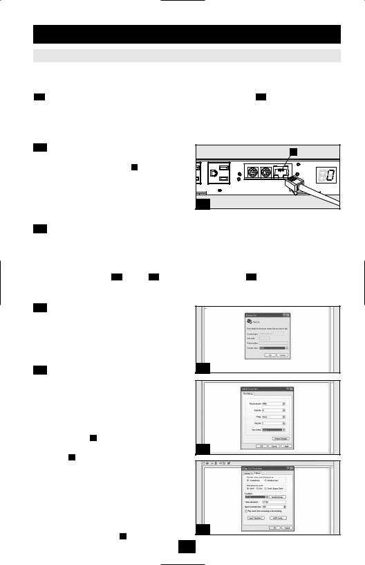
5-2 Configure Terminal Emulation Program:
Open a VT100-compatible terminal emulation program (such as the HyperTerminal program bundled with Microsoft® Windows®) on a computer with an available DB9 serial port. (A notebook computer may be the most convenient choice.) Set the terminal emulation program to use the COM port A that corresponds to the computer’s DB9 serial port. Specify the
parameters B required to communicate with the PDU terminal interface:
Bits per second: |
9600 |
Data bits: |
8 |
Parity: |
None |
Stop bits: |
1 |
Flow control: |
None |
If the terminal emulation program supports multiple emulation modes, you may also need to specify VT100 emulation C .
A
B
C
5
Installation continued
Networking the PDU continued
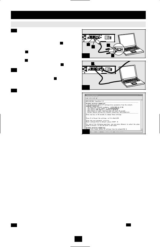
5-3 Connect PDU to Computer: Use the miniDIN to DB9 serial cable (part number 73-1025) included with the PDU to connect the PDU to the computer. The circular connector A at one end of the cable attaches to the 8-pin mini-DIN serial port B on the PDU. (Align the connector carefully to avoid damaging the pins.) The DB9 connector C at the other end of the cable connects to the computer's serial port D .
5-4 Connect PDU to Network: While the PDU is powered, connect a standard Ethernet patch cable to the RJ-45 Ethernet port A on the PDU.
Note: This port is not compatible with PoE (Power over Ethernet) applications.
B |
A |
C |
|
|
|
5-3 |
|
D |
A |
5-4
5-5 Configure PDU in Terminal Mode: After a |
|
|
brief pause, an initialization page should appear |
|
|
in the terminal emulation program. Press any |
|
|
key on the keyboard within 10 seconds to |
|
|
change the PDU settings. (If the 10-second |
|
|
period has elapsed, you can reboot the PDU by |
|
|
powering down completely and then restoring |
|
|
power.) |
|
|
Follow the sequence of responses below in order |
|
|
to assign an IP address to the PDU. The default |
5-5 |
|
terminal mode root password is TrippLite. |
||
|
||
Sample IP settings are shown - supply your own |
|
|
IP information when you configure your PDU. |
|
Press A to Accept the settings, or M to Modify? M
Enter the root password: *********
Reset configuration to default values (Y/N)? N
For each of the following questions, you can press <Return> to select the value shown in braces, or you can enter a new value.
NETWORK INTERFACE PARAMETERS:
Should this target obtain IP settings from the network?[N] N
Static IP address [192.168.1.19]? 192.168.0.123
Static IP address is 192.168.0.123
Subnet Mask IP address [255.255.0.0]? 255.255.255.0
Subnet Mask IP address is 255.255.255.0
Gateway address IP address [192.168.1.1]? 192.168.0.1
Gateway address IP address is 192.168.0.1
You can also change the root password, real-time clock and other settings. (Tripp Lite recommends against changing the default settings unless you are an advanced user with a specific purpose.) After you have finished entering settings, the PDU will save changes to memory and reboot (this may take several minutes). After the PDU reboots, the initialization page should display the new static IP settings.
5-6 Remove Serial Cable: Remove the serial cable from the PDU and proceed to Step 6-1 .
6

Installation continued
Networking the PDU continued
Testing Network Connection
6-1 Access PDU with Web Browser: After an IP address has been assigned to the PDU, attempt to access it with a Web browser that supports frames, forms and Java™. Open a Web browser on a computer connected to the LAN and enter the IP address assigned to the PDU. You should be prompted for a password A . The user name is admin and the default password is admin. After you enter the user name and password, the PowerAlert Status page B will appear in the browser window. For more information about configuration and operation of the PDU via the PowerAlert interface, refer to the SNMPWEBCARD User's Guide, included on the CD-ROM bundled with the PDU.
Note for Network Management System Users Only: Two MIB files - Tripplite.mib and RFC1628.mib - must be loaded on each Network Management Station that will monitor the PDU via SNMP. The files are provided on the CD-ROM included in the product package.
A
B
7
Features
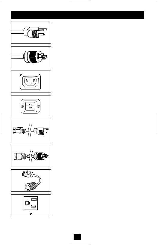
Primary AC Input Power Cord (Model PDUMH15ATNET):
The cord is permanently attached to the PDU and has a NEMA 5-15P plug.
Primary AC Input Power Cord (Model PDUMH20ATNET):
The cord is permanently attached to the PDU and has a NEMA
L5-20P plug.
Secondary AC Input Power Inlet (Model PDUMH15ATNET):
The IEC-320-C14 inlet connects to the detachable Secondary AC
Input Power Cord.
Secondary AC Input Power Inlet (Model PDUMH20ATNET):
The IEC-320-C20 inlet connects to the detachable Secondary AC
Input Power Cord.
Secondary AC Input Power Cord (Model PDUMH15ATNET):
The detachable cord has an IEC-320-C13 connector and a NEMA 5-15P plug.
Secondary AC Input Power Cord (Model PDUMH20ATNET):
The detachable cord has an IEC-320-C19 connector and a NEMA
L5-20P plug.
Input Plug Adapters (Model PDUMH20ATNET): The adapters convert NEMA L5-20P input plugs to NEMA 5-20P input plugs.
NEMA 5-15R Outlets (Model PDUMH15ATNET): During normal operation, the outlets distribute AC power to connected equipment. When an outlet is live, the associated LED illuminates.
8
Features continued
A

 B
B
NEMA 5-15/20R Outlets (Model PDUMH20ATNET): During normal operation, the outlets distribute AC power to connected equipment. When an outlet is live, the associated LED illuminates.
Digital Load Meter (Ammeter): The total electrical current used by the PDU is displayed on the digital meter in amperes.
Input Source Indicator: When the PDU is connected to a live AC power source, the Primary or Secondary input LED illuminates to indicate which source is supplying power to the PDU outlets.
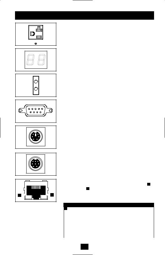
Factory Port: The port is reserved for configuration by factory authorized personnel only. Do not connect anything to the port.
PS/2 Port: Use this port to connect a Tripp Lite ENVIROSENSE environmental sensor to provide remote temperature/humidity monitoring and a dry contact interface to control and monitor alarm, security and telecom devices. Contact Tripp Lite Customer Support at (773) 869-1234 for ordering information. Note: Do not connect a keyboard or mouse to this port.
Mini-DIN Serial Port: Use this port to provide a direct terminal connection to a computer with a terminal emulation program. A serial cable (part number 73-1025) is included with the PDU. If you need to order a replacement cable, contact Tripp Lite Customer Support at (773) 869-1234.
Ethernet Port: Use this RJ-45 jack to connect the PDU to the network with a standard Ethernet patch cable. The Link LED A and Status LED B indicate several operating conditions, as shown in the table below. This port is not compatible with PoE (Power Over Ethernet) applications.
Network Operating Conditions
A Link LED Color
|
Off |
No Network Connection |
|
|
Flashing Amber |
100 Mbps Network Connection |
|
|
Flashing Green |
10 Mbps Network Connection |
|
|
B |
Status LED Color |
|
|
|
|
|
|
Off |
Card Not Initialized |
|
|
Steady Green |
Card Initialized and Operational |
|
|
Flashing Amber |
Error - Card Not Initialized |
|
|
|
|
|
9
Configuration and Operation
Automatic Transfer Switch
When the Primary and Secondary inputs are both connected to Tripp Lite UPS Systems, the PDU operates as an Automatic Transfer Switch, providing redundant input power for high availability applications. Under normal operating conditions, the PDU will distribute power from the Primary input source, switching to the Secondary input source under certain conditions. The PDU will switch to the Primary source whenever it is Good according to the PDU input voltage definitions (see below).
Automatic Transfer Switch Source Selection
Upon power-up, the PDU looks for a source >85V. If it is unable to find a source >85V, it remains off.
Input voltage definitions:
99V |
< Vin < 139V |
Good |
75V |
< Vin < 99V |
Fair |
Vin < 75V |
Bad |
|
In normal operation (after power-up), if the selected source is no longer Good, the PDU will attempt to switch to the other source, but only if the other source is Good. If the selected source becomes Fair and the other source is not Good, the PDU will keep the loads connected to the selected source until the selected source becomes Bad, at which point the loads will be disconnected (note that the source selection doesn't change). After the loads are disconnected, they remain disconnected until the selected source becomes >85V, or until the other source becomes Good.
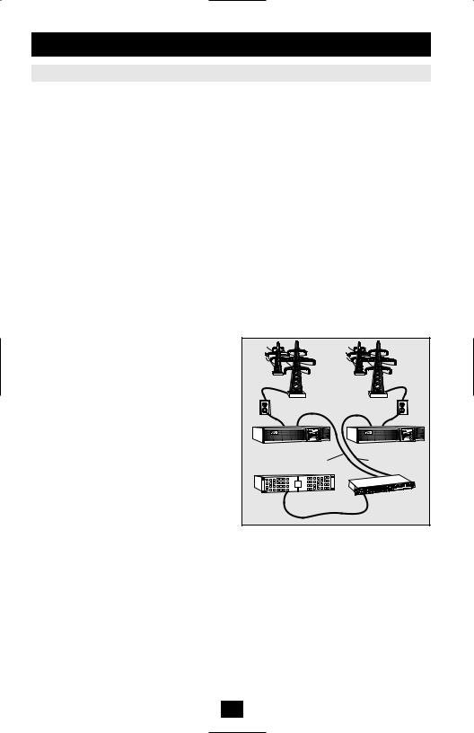
Preferred Configuration
The Automatic Transfer Switch function provides increased availability when the Primary and Secondary inputs of the PDU are connected to separate Tripp Lite UPS Systems that are connected to separate utility power sources. For maximum availability, Tripp Lite recommends using matching SmartOnline UPS Systems with pure sine wave output for the Primary and Secondary input power sources. The automatic transfer switch function will be compromised if the primary and secondary inputs are connected to the same utility power source.
Utility B |
Utility A |
Facility Circuit |
Facility Circuit |
Secondary UPS |
Primary UPS |
Secondary Input Cord |
Primary Input Cord |
Critical Equipment |
PDUMH15ATNET |
Loads |
|
10
Configuration and Operation continued
Quick Test
After installing the PDU and connecting equipment, you may test the Automatic Transfer Switch function by temporarily shutting down the UPS system connected to the Primary AC input. When the Primary input UPS is no longer supplying AC power, the PDU will switch from the Primary input to the Secondary input, and the Secondary input LED will illuminate. When the Primary input UPS has been restarted and resumes supplying AC power, the PDU will switch back to the Primary input.
Primary Input Active |
Secondary Input Active |
Note: The primary and secondary inputs must be connected to separate sources of utility power. The automatic transfer switch function will be compromised if the primary and secondary inputs are connected to the same utility power source. Do not perform a test with equipment that must remain in productive operation. Any test procedure must prepare for the contingency that the equipment may lose power. Do not test the PDU by detaching power cords which are connected to live power sources, as this eliminates the connection to ground and places your equipment at risk.
Remote Monitoring and Control
The PDU provides remote monitoring A , outlet control B and more via Web browser, telnet and SNMP-based Network Management Systems. For more information about configuration and operation of the PDU via the PowerAlert Web browser interface, refer to the SNMPWEBCARD User's Guide, included on the CD-ROM bundled with the PDU.
A
B
11
 Loading...