


WARRANTYFREE.com/warranty |
|||
REGISTRATION: |
a |
Lite |
|
|
|
for |
|
|
todayTripp |
|
|
onlinea |
|
|
|
register |
win.tripplite |
|
|
to |
|
|
|
www |
|
|
|
chance— |
|
|
|
product |
|
|
|
Owner’s Manual
VS UPS Systems
OMNIVS800, OMNIVS1000, OMNIVS1500, OMNIVS1500XL
Not suitable for mobile applications.
Important Safety Instructions |
2 |
|
|
|
|
Quick Installation |
3 |
|
|
|
|
Basic Operation |
4 |
|
|
|
|
Storage & Service |
7 |
|
|
|
|
Warranty Registration |
7 |
|
|
|
|
Español |
8 |
|
|
|
|
Français |
16 |
|
|
1111 W. 35th Street Chicago, IL 60609 USA Customer Support: (773) 869-1234 • www.tripplite.com
Copyright © 2007 Tripp Lite. All rights reserved.

Important Safety Instructions
SAVE THESE INSTRUCTIONS
This manual contains instructions and warnings that should be followed during the installation, operation and storage of this product. Failure to heed these warnings will void the warranty.
UPS Location Warnings
•Install the UPS indoors, away from excess moisture or heat, dust or direct sunlight.
•For best performance, keep the indoor temperature between 32º F and 104º F (0º C and 40º C).
•Leave adequate space around all sides of the UPS for proper ventilation.
•Do not mount unit with its front or rear panel facing down (at any angle). Mounting in this manner will seriously inhibit the unit's internal cooling, eventually causing product damage not covered under warranty.
UPS Connection Warnings
•Connect the UPS directly to a properly grounded AC power outlet. Do not plug the UPS into itself; this will damage the UPS.
•Do not modify the UPS plug, and do not use an adapter that would eliminate the ground connection.
•Do not use extension cords to connect the UPS to an AC outlet. The warranty will be void if anything other than Tripp Lite surge suppressors are used to connect the UPS to an outlet.
•If the UPS receives power from a motor-powered AC generator, the generator must provide clean, filtered, computer-grade output.
Equipment Connection Warnings
•Use of this equipment in life support applications where failure of this equipment can reasonably be expected to cause the failure of the life support equipment or to significantly affect its safety or effectiveness is not recommended. Do not use this equipment in the presence of a flammable anesthetic mixture with air, oxygen or nitrous oxide.
•Do not connect surge suppressors or extension cords to the output of the UPS. This may damage the UPS and will void the surge suppressor and UPS warranties.
Battery Warnings
•The UPS does not require routine maintenance. Do not open the UPS for any reason. There are no user-serviceable parts inside.
•Batteries can present a risk of electrical shock and burns from high short-circuit current. Observe proper precautions. Do not dispose of the batteries in a fire. Do not open the UPS or batteries. Do not short or bridge the battery terminals with any object. Use tools with insulated handles. Battery replacement should be performed only by authorized service personnel using the same number and type of batteries (Sealed Lead-Acid). The batteries are recyclable. Refer to your local codes for disposal requirements or in the USA only call 1-800-SAV-LEAD or 1-800-8-BATTERY (1-800-822-8837) or visit www.rbrc.com for recycling information. Tripp Lite offers a complete line of UPS System Replacement Battery Cartridges (R.B.C.). Visit Tripp Lite on the Web at www.tripplite.com/support/battery/index.cfm to locate the specific replacement battery for your UPS.
•Do not attempt to add external batteries unless your UPS includes external battery connectors.
2

Quick Installation
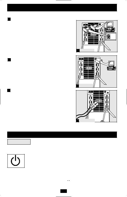
1 Connect the UPS to
a 120V AC electrical outlet.
Make sure the outlet does not share a circuit with a heavy electrical load such as an air conditioner or refrigerator.
2 Plug your equipment into the UPS.
The battery backup receptacles AA provide filtered AC power during normal operation and provide battery backup power during blackouts and extreme voltage irregularities. Connect your computer and monitor to the battery backup receptacles.*
One or more surge-only receptacles BB attached to short cords at the rear of the UPS provide AC line protection without battery backup. These receptacles will protect equipment that would overload the UPS or greatly reduce backup time if connected to the battery backup receptacles.
Note: High-amperage equipment such as laser printers, refrigerators, air conditioners and electric heaters should not be connected to the UPS.
* Your UPS is designed to only support computer equipment. You will overload the UPS if the total VA ratings for all the equipment you connect to the (A) outlets exceeds the UPS’s Output Capacity. To find your equipment’s VAratings, look on their nameplates. If the equipment is listed in amps, multiply the number of amps by 120 to determine VA. (Example: 1 amp x 120 = 120 VA.) If you are unsure if you have overloaded the
(A) outlets, run a self-test (see “MUTE/TEST” button description).
3 Select UPS Operating Mode.
Press the ON/OFF button to toggle the UPS between the ON (“ ” LED lit) and the OFF (“
 ” LED not lit) modes.
1 |
A
A
2 |
B |
OMNIVS800 |
|
|
A |
|
A |
2 |
B |
OMNIVS1000 |
|
|
A |
|
A |
 B
B
OMNIVS1500XL & 2 OMINVS1500*
3
*OMNIVS1500 does not feature external battery connection
3
Quick Installation optional
These connections are optional. The UPS will function properly without these connections.
1 |
Phone Line/Network Line Surge |
|
|
Suppression |
|
|
The UPS has jacks which protect against surges over a |
|
|
phone line or network data line. |
|
|
Using telephone cords or network data cables as |
|
|
appropriate, connect the wall jack to the UPS jack marked |
|
|
“IN.” Connect equipment to the UPS jack marked “OUT.” |
|
|
Make sure the equipment connected to the UPS jacks is |
|
|
also protected against surges on the AC line. NOTE: |
1 OMNIVS1500XL |
|
Tel/DSL/Ethernet (RJ-45) jacks not compatible with PoE |
|
|
|
|
|
(Power over Ethernet) applications. |
|
2 |
USB Communications |
Use a USB cable to connect the computer’s USB port to the USB port of the UPS. Download the PowerAlert UPS monitoring software program appropriate for the computer’s operating system from www.tripplite.com/software/ and install it.
|
External Battery Connection |
2 |
OMNIVS1500XL |
|
(OMNIVS1500XL only) |
||
3 |
|
|
|
|
All UPS models come with a robust internal battery system; |
|
|
|
select models feature connectors that accept an optional |
|
|
|
external battery pack (sold separately from Tripp Lite) to |
|
|
|
provide additional runtime. Adding an external battery will |
|
|
|
increase recharge time as well as runtime. See battery pack |
|
|
|
owner’s manual for complete installation instructions. Make |
|
|
|
sure cables are fully inserted into their connectors. Small |
|
|
|
sparks may result during battery connection; this is normal. |
|
|
|
Do not connect or disconnect battery pack when the UPS is |
3 OMNIVS1500XL |
|
|
running on battery power. |
||
|
|
|
|
Basic Operation
Buttons
Switch the Operating Mode: While the UPS is plugged into a live AC outlet, ON/OFF Button: press the ON/OFF button and hold it until the UPS beeps (about 2 seconds) to
toggle between ON and OFF.
•ON Mode: ENABLES battery backup. UPS Conditions: The UPS charges the
battery and supplies power to the outlets while receiving utility line power. The “ ” indicator light will illuminate. If utility power fails, the UPS provides power from battery.
Cold-Start: Cold start the UPS to use it as a stand-alone power source when utility power is not present (if the UPS battery is charged). To cold start the UPS, press and hold the ON/OFF button until the UPS beeps (about 2 seconds), then release it. The “ 


 ” indicator will illuminate and AC power inverted from stored battery power will be provided to the outlets.
4
Basic Operation continued
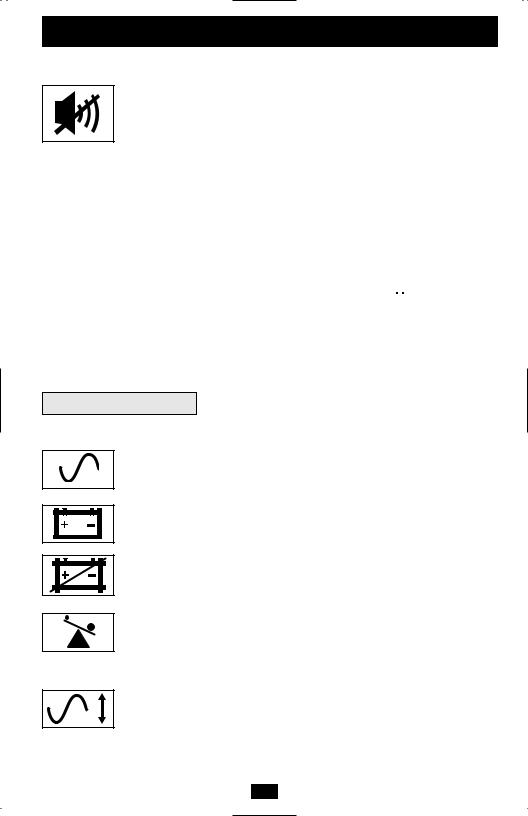
MUTE/TEST Button:
Silence the UPS On-Battery Alarm: Press and hold this button to silence the UPS on-battery alarm, a series of short beeps followed by a brief pause that is activated when the UPS is providing AC power from battery. Note: When the battery is nearly depleted, the low battery alarm—a continuous beep that cannot be silenced—will warn to shut down connected equipment immediately.
Run a Self-Test: To run a self-test, leave connected equipment on. With the UPS plugged in and ON, press and hold the button until the UPS beeps (about 2 seconds) then release it.
Self-Test Results: All LEDs will be lit and the UPS will emit several short beeps as it momentarily switches to battery to test charge and load capacity. The test will last up to 10 seconds. If the inverter is overloaded, the “ 
 ” LED will stay lit and the UPS will continue to beep after the test; if this happens, remove some of the load from the “UPS/Surge” outlets and run the self-test again. If the batteries are weak, the “
  ” LED will stay lit and the UPS will continue to beep after the test. If this happens, let the UPS charge its batteries for 12 hours and repeat the test. If the condition persists, contact Tripp Lite for service. CAUTION: Do not unplug the UPS to test its batteries. This will remove safe electrical grounding and may introduce a damaging surge into network connections.
Indicator Lights
All Indicator Light descriptions apply when the UPS is plugged into an AC outlet and turned on.
LINE POWER: This green light will illuminate whenever the UPS is ON and receiving normal AC line power.
BATTERY POWER: This yellow light will illuminate when the UPS is providing equipment with battery power.
REPLACE BATTERY: This red light will illuminate continuously after the UPS runs a self-test to indicate that the battery is weak. If it remains lit after allowing the UPS to charge for twelve hours and running a second self-test, contact Tripp Lite for service.
OVERLOAD: This red light will illuminate continuously to indicate that the UPS is overloaded when the UPS is providing power from battery or after the UPS runs a self-test. If it lights up, immediately remove some of the equipment connected to the “UPS/Surge” outlets and run a self-test. Large overloads may cause the UPS to shut down.
“VOLTAGE CORRECTION” LED (select models only): Lights green whenever your UPS is automatically correcting high or low AC line voltage. The UPS will also click gently. These are normal, automatic operations of your UPS, and no action is required on your part.
5
Basic Operation continued |
|||
Other UPS Features |
|||
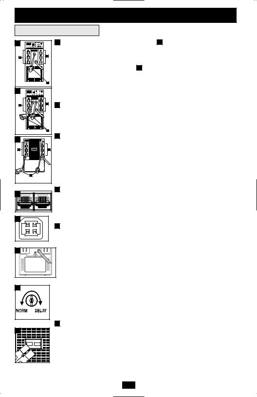
1 |
1 |
AC Outlets: The battery backup receptacles A provide filtered AC power during |
|
|
|
normal operation and provide battery backup power during blackouts and extreme |
|
|
A |
voltage irregularities. Connect your computer and monitor to the battery backup |
|
A |
receptacles. |
||
|
|||
|
|
One or more surge-only receptacles B attached to short cords at the rear of the UPS |
|
|
|
provide AC line protection without battery backup. These receptacles will protect |
|
|
|
equipment that would overload the UPS or greatly reduce backup time if connected |
|
|
B |
to the battery backup receptacles. Note: High-amperage equipment such as laser |
|
OMNIVS800 |
|
||
1 |
|
printers, refrigerators, air conditioners and electric heaters should not be connected to |
|
|
|
the UPS. |
|
A |
A |
2 Telephone/DSL/Ethernet Protection Jacks: These |
jacks protect equipment |
|
|
|
|
|
|
against surges over a telephone or data line. Connecting |
equipment to these jacks |
|
|
is optional. The UPS will work properly without this connection. Note: Models |
|
|
|
with tel/DSL/Ethernet (RJ-45) jacks not compatible with PoE (Power over |
|
|
|
Ethernet) applications. |
|
B
OMNIVS1000
1 |
|
3 USB Communication Port: This port can connect your UPS to any computer for |
|
|
automatic file saves and unattended shutdown in the event of a power failure. Use |
||
|
|
||
A |
A |
with Tripp Lite's PowerAlert Software (available as a FREE download at |
|
www.tripplite.com) and appropriate USB cable. A USB cable may be included with |
|||
|
|
||
|
|
your UPS. If the appropriate cable did not come with your UPS, a user-supplied |
|
|
|
USB cable may then be used to connect your UPS to your computer. This |
|
|
|
connection is optional. The UPS will work properly without this connection. Note: |
|
|
B |
This UPS System provides basic communication compatibility with most |
|
OMNIVS1500XL & OMINVS1500* |
integrated Windows®, Macintosh® and Linux® power management applications. |
||
2 |
|
4 Battery Replacement Door: Under normal conditions, the original battery in the |
|
|
UPS will last several years. Battery replacement should be performed only by |
||
|
|
qualified service personnel. Refer to “Battery Warnings” in the Safety section. |
|
|
|
Should the UPS require battery replacement, visit Tripp Lite on the Web at |
|
|
|
www.tripplite.com/support/ battery/index.cfm to locate the specific replacement |
|
3 |
|
battery for the UPS. |
|
|
|
||
|
|
5 Power Sensitivity Adjustment: This dial is normally set fully counterclockwise, |
|
|
|
which enables the UPS to protect against waveform distortions in its AC input. |
|
|
|
When such distortions occur, the UPS will normally switch to providing PWM |
|
|
|
sinewave power from its battery reserves for as long as the distortions are present. |
|
|
|
In some areas with poor utility power or where the UPS’s input power comes from |
|
4a backup generator, frequent brownouts and/or chronic waveform distortion could cause the UPS to switch to battery too often, draining its battery reserves. It may be possible to reduce how often the UPS switches to battery due to waveform distortion or brownouts by experimenting with different settings for this dial. As the dial is turned clockwise, the UPS becomes more tolerant of variations in its input power’s AC waveform and switches to battery less often. NOTE: The further the
5dial is adjusted clockwise, the greater the degree of waveform distortion the UPS will allow to pass to connected equipment. When experimenting with different settings for this dial, operate connected equipment in a safe test mode so that the effect on the equipment of any waveform distortions in the UPS’s output can be evaluated without disrupting critical operations. The experiment should last long enough to assure that all expected line conditions are encountered.
6 |
6External Battery Connector (Select Models Only): Use to connect a single Tripp Lite external battery pack for additional runtime. Refer to instructions available with the battery pack for complete connection information and safety warnings.
Automatic Voltage Regulation: The UPS will automatically correct abnormal AC line voltage. When automatic voltage regulation is operating, the UPS may click gently. This is a normal, automatic operation of the UPS, and no action is required.
OMNIVS1500XL
*OMNIVS1500 does not feature external battery connection
6

Storage & Service
Storage
All connected equipment should be turned off, then disconnected from the UPS to avoid battery drain. Unplug the UPS from its AC receptacle, then press and hold its ON/OFF button to deactivate it. The UPS is now ready for storage. When storing the UPS for an extended period of time, fully recharge the UPS batteries once every three months by plugging the UPS into a live AC outlet and letting the UPS charge for 12 hours. If the UPS batteries are discharged for an extended period of time, they will suffer a permanent loss of capacity.
Service
If returning the UPS for service, contact the local Tripp Lite dealer or distributor. They will provide a referral to a service center. Please carefully pack the UPS using the ORIGINAL PACKING MATERIAL that came with the unit. Enclose a letter describing the symptoms of the problem. If the UPS is within the warranty period, enclose a copy of the sales receipt.
Warranty Registration
Visit www.tripplite.com/warranty today to register the warranty for your new Tripp Lite product. You'll be automatically entered into a drawing for a chance to win a FREE Tripp Lite product!*
* No purchase necessary. Void where prohibited. Some restrictions apply. See website for details.
FCC RADIO/TV INTERFERENCE NOTICE: Note: This equipment has been tested and found to comply with the limits for a Class B digital device, pursuant to Part 15 of the FCC Rules. These limits are designed to provide reasonable protection against harmful interference in a residential installation. This equipment generates, uses and can radiate radio frequency energy, and if not installed and used in accordance with the instruction manual, may cause interference to radio communications. However, there is no guarantee that interference will not occur in a particular installation. If this equipment does cause harmful interference to radio or television reception, which can be determined by turning the device off and on, the user is encouraged to try to correct the interference using one or more of the following measures: reorient or relocate the receiving antenna; increase the separation between the equipment and receiver; connect the equipment into an outlet on a circuit different from that which the receiver is connected; consult the dealer or an experienced radio/television technician for help. The user must use shielded cables and connectors with this product. Any changes or modifications to this product not expressly approved by the party responsible for compliance could void the user's authority to operate the equipment.
FCC Part 68 Notice (United States Only):
If your Modem/Fax Protection causes harm to the telephone network, the telephone company may temporarily discontinue your service. If possible, they will notify you in advance. If advance notice isn't practical, you will be notified as soon as possible. You will be advised of your right to file a complaint with the FCC. Your telephone company may make changes in its facilities, equipment, operations or procedures that could affect the proper operation of your equipment. If it does, you will be given advance notice to give you an opportunity to maintain uninterrupted service. If you experience trouble with this equipment's Modem/Fax Protection, please call Tripp Lite Technical Support at (773) 869-1234 for repair/warranty information. The telephone company may ask you to disconnect this equipment from the network until the problem has been corrected or you are sure the equipment is not malfunctioning. There are no repairs that can be made by the customer to the Modem/Fax Protection. This equipment may not be used on coin service provided by the telephone company. Connection to party lines is subject to state tariffs. (Contact your state public utility commission or corporation commission for information.)
EQUIPMENT ATTACHMENT LIMITATIONS (Models with the Industry Canada label in Canada only): NOTICE: The Industry Canada label identifies certified equipment. This certification means that the equipment meets the telecommunications network protective, operational and safety requirements as prescribed in the appropriate Terminal Equipment Technical Requirements Document(s). The Department does not guarantee the equipment will operate to the user’s satisfaction.
Before installing this equipment, users should ensure that it is permissible to be connected to the facilities of the local telecommunications company. The equipment must also be installed using an acceptable method of connection. The customer should be aware that the compliance with the above conditions might not prevent degradation of service in some situations.
Repairs to certified equipment should be coordinated by a representative designated by the supplier. Any repairs or alterations made by the user to this equipment, or equipment malfunctions, may give the telecommunications company cause to request the user to disconnect the equipment.
Users should ensure for their own protection that the electrical ground connections of the power utility, telephone lines and internal metallic water pipe system, if present, are connected together. This precaution may be particularly important in rural areas. Caution: Users should not attempt to make connections themselves, but should contact the appropriate electric inspection authority, or electrician, as appropriate.
Regulatory Compliance Identification Numbers
For the purpose of regulatory compliance certifications and identification, your Tripp Lite product has been assigned a unique series number. The series number can be found on the product nameplate label, along with all required approval markings and information. When requesting compliance information for this product, always refer to the series number. The series number should not be confused with the marking name or model number of the product.
Tripp Lite has a policy of continuous improvement. Product specifications are subject to change without notice.
Note on Labeling: Two symbols are used on the label. V~ : AC Voltage V  : DC Voltage
7

Manual de operación
Sistemas UPS Omni VS
OMNIVS800, OMNIVS1000, OMNIVS1500, OMNIVS1500XL
No conveniente para los usos móviles.
Importantes instrucciones de seguridad |
9 |
|
|
|
|
Instalación rápida |
10 |
|
|
|
|
Operación básica |
11 |
|
|
|
|
Almacenamiento y servicio |
15 |
|
|
|
|
English |
1 |
|
|
|
|
Français |
16 |
|
|
1111 W. 35th Street Chicago, IL 60609 EE.UU. Asistencia al cliente: +1 (773) 869-1234 • www.tripplite.com
© 2007 Tripp Lite. Todos los derechos reservados.
 Loading...