


User’s Guide
M/GE-PSW-SX-01, M/GE-PSW-LX-01
Stand-Alone Media Converters
•Copper to Fiber
•10/100/1000Base-T to 1000Base-X
The miniature plug-and-play M/GE-PSW-xX-01, 2- port Ethernet/Fast Ethernet bridging media converters allow integrating fiber optic cable to
10/100/1000 Unshielded Twisted Pair (UTP) environments while providing a spacesaving alternative to traditional sized media converters.
M/GE-PSW-xX-01: Auto-Negotiation, AutoCross, Far End Fault (FEF)
Part Number |
Copper - Port |
Fiber-Optic -Port |
|
10/100/1000Base-T |
1000Base-FX |
M/GE-PSW-SX-01 (SC) |
RJ-45 |
SX, 850 nm, multimode 62.5/125 |
|
100 m (328 ft)* |
200m (722 ft), 50/125 550m (1,805 ft) |
M/GE-PSW-LX-01 (SC) |
RJ-45 |
LX, 1310 nm single mode |
|
100 m (328 ft)* |
10 km (2.1 miles)* |
*Typical maximum cable distance; actual distance is dependent upon the physical characteristics of the network.
Installation . . . . . . . . . . . . |
. . . . . .2 |
Operation . . . . . . . . . . . . . . |
. . . . .6 |
Cable Specifications . . . . . . |
. . . .10 |
Technical Specifications . . . |
. . . .11 |
Troubleshooting . . . . . . . . . |
. . . .12 |
Contact Us . . . . . . . . . . . . . |
. . . .13 |
Declaration of Conformity |
. . . . .14 |
Compliance Information . . . |
. . . .15 |

M/GE-PSW-xX-01
Installation
Copper and fiber ports
The illustration below shows the front panel of the M/GE-PSW-xX-01 media converters.
Front Panel
TP Link/Active
Fiber Link/Activity
TX RX
Copper Port
Fiber Port
Power ON LED
Electrostatic Discharge (ESD)
Always observe the following ESD precautions when installing or handing the M/GE-PSW-xX-01 media converter:
•Do not remove the converter from its protective packaging until you are ready to install it.
•Wear an ESD wrist grounding strap before handling any module or component. If you do not have a wrist strap, maintain grounded contact with the system unit
throughout any procedure requiring ESD protection.
Installation -- Continued
Connect the fiber cable
Full duplex (always ON) is on the fiber side only; therefore, the 512-Bit Rule does not apply. The cable lengths are constrained by the cable requirement.
1.Locate or build IEEE 803.2™ compliant 1000Base-X fiber cable with male, two-stranded TX to RX connectors installed at both ends.
2.Connect the fiber cable to the M/GE-PSW-xX-01 media converters as follows:
•Connect the male TX cable connector to the female TX port.
•Connect the male RX cable connector to the female RX port.
3.Connect the fiber cable to the other device (another media converter, hub, etc.) as follows:
•Connect the male TX cable connector to the female RX port.
•Connect the male RX cable connector to the female TX port.
Connect fiber cable |
Connect fiber cable |
to media converter |
to other device |
as shown. |
(media converter, |
|
hub, etc.) as shown |
RX |
RX |
TX |
TX |
Note: With AutoCross permanently enabled, the link LED only lights when a valid end-to-end connection is made.
2 |
Tech Support: 1-800-260-1312 International: 00-1-952-941-7600 (24 hours) |
techsupport@transition.com -- Click the “Transition Now” link for a live Web chat. |
3 |
M/GE-PSW-xX-01
Installation -- Continued
Connect the twisted-pair copper cable
The AutoCross feature allows either MDI (straight-through) or MDI-X (crossover) cable connections to be configured automatically, according to network conditions.
1.Locate or build IEEE 803.2™ compliant 10/100/1000Base-T cables with RJ45 connectors installed at both ends.
2.Connect the RJ-45 connector at one end of the cable to the RJ-45 port on the M/GE-PSW-xX-01 media converter.
3.Connect the RJ-45 connector at the other end of the cable to the RJ-45 port on the other device (switch, workstation, etc.).
Installation -- Continued
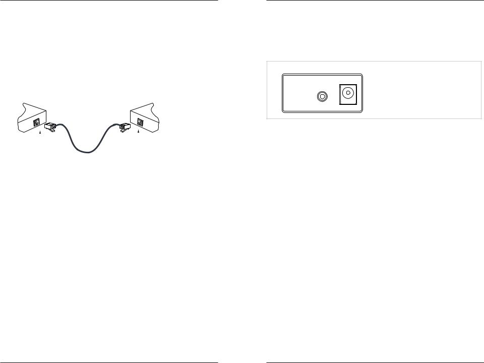
Powering the media converter
The M/GE-PSW-xX-01 media converter is powered by using a DC power adapter through the barrel connector on its rear panel, as shown below.
M/GE-PSW-xX-01 Back Panel Power
Back Panel
Barrel Connector
 5-28 VDC
|
|
|
|
|
|
|
|
RJ-45 port |
RJ-45 port |
||
on the media |
on the other device |
||
converter |
(switch, work station, etc.) |
||
|
|
|
|
Note: With AutoCross permanently enabled, the link LED only lights when a valid end-to-end connection is made.
Power adapter
AC power
1.Connect the barrel connector of the power adapter to the media converter’s power port (located on the back panel of the media converter).
2.Connect the power adapter plug to AC power.
3.Verify that the media converter is powered up by observing the illuminated LED power indicator light on the front panel.
DC power
Consult the user’s guide for the Transition Networks SPS-1872-SA DC external power supply for powering the media converter.
4 |
Tech Support: 1-800-260-1312 International: 00-1-952-941-7600 (24 hours) |
techsupport@transition.com -- Click the “Transition Now” link for a live Web chat. |
5 |
 Loading...