


 Loading...
Product Catalog
Voyager™ — TS*/YS*/WS*
Packaged Cooling, Gas/Electric & Heat Pump
15–25 Tons, 50 Hz
August 2012 |
RT-PRC034-EN |
Introduction
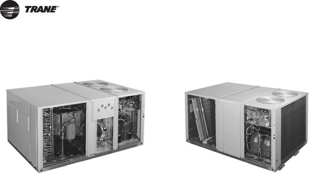
Packaged Gas/Electric |
Packaged Cooling/Heat Pump |
Packaged Rooftop Air Conditioners
Through the years, Trane has designed and developed the most complete line of Packaged Rooftop products available in the market today. Trane was the first to introduce the Micro—microelectronic unit controls—and has continued to improve and revolutionize this design concept.
The ReliaTel control platform offers the same great features and functionality as the original Micro, with additional benefits for greater application flexibility.
Voyager continues to provide the highest standards in quality and reliability, comfort, ease of service, and the performance of Trane light commercial products.
Trane customers demand products that provide exceptional reliability, meet stringent performance requirements, and are competitively priced. Trane delivers with Voyager.
Voyager features cutting edge technologies: reliable compressors, Trane engineered ReliaTel controls, computer-aided run testing, and Integrated Comfort™ Systems. So, whether you’re the contractor, the engineer, or the owner you can be certain Voyager Products are built to meet your needs.
Trademarks
and the logo, Frostat, Integrated Comfort, ReliaTel, Tracer, are trademarks of in the United States and other countries. All trademarks referenced in this document are the trademarks of their respective owners.
Revision Summary
RT-PRC034-EN (20 August 2012)
•New configurable model number
•New optional features: Condensate Overflow Switch, MERV 8 and Filter Removal Tool, Stainless Steel Drain Pan
•Updated Features/Benefits, Model Number Description, General Data, Electrical Data, Mechanical Specifications
© 2012 Trane All rights reserved |
RT-PRC034-EN |

Table of Contents
Introduction . . . . . . . . . . . . . . . . . . . . . . . . . . . . . . . . . . . . . . . . . . . . . . . . . . . . . . . . . . . . 2
Features and Benefits . . . . . . . . . . . . . . . . . . . . . . . . . . . . . . . . . . . . . . . . . . . . . . . . . . . 4
Standard Features . . . . . . . . . . . . . . . . . . . . . . . . . . . . . . . . . . . . . . . . . . . . . . . . . 4
Options . . . . . . . . . . . . . . . . . . . . . . . . . . . . . . . . . . . . . . . . . . . . . . . . . . . . . . . . . . . 5
Other Benefits . . . . . . . . . . . . . . . . . . . . . . . . . . . . . . . . . . . . . . . . . . . . . . . . . . . . . 6
Standard Features . . . . . . . . . . . . . . . . . . . . . . . . . . . . . . . . . . . . . . . . . . . . . . . . . 6
Variety of Options . . . . . . . . . . . . . . . . . . . . . . . . . . . . . . . . . . . . . . . . . . . . . . . . . . 9
Other Benefits . . . . . . . . . . . . . . . . . . . . . . . . . . . . . . . . . . . . . . . . . . . . . . . . . . . . 12
Application Considerations . . . . . . . . . . . . . . . . . . . . . . . . . . . . . . . . . . . . . . . . . . . . . 15
Selection Procedure (SI/IP) . . . . . . . . . . . . . . . . . . . . . . . . . . . . . . . . . . . . . . . . . . . . . |
16 |
SI Selection Procedure . . . . . . . . . . . . . . . . . . . . . . . . . . . . . . . . . . . . . . . . . . . . . |
16 |
IP Selection Procedure . . . . . . . . . . . . . . . . . . . . . . . . . . . . . . . . . . . . . . . . . . . . . |
19 |
Model Number Descriptions . . . . . . . . . . . . . . . . . . . . . . . . . . . . . . . . . . . . . . . . . . . . |
22 |
General Data . . . . . . . . . . . . . . . . . . . . . . . . . . . . . . . . . . . . . . . . . . . . . . . . . . . . . . . . . . |
24 |
Performance Data . . . . . . . . . . . . . . . . . . . . . . . . . . . . . . . . . . . . . . . . . . . . . . . . . . . . . |
30 |
Controls . . . . . . . . . . . . . . . . . . . . . . . . . . . . . . . . . . . . . . . . . . . . . . . . . . . . . . . . . . . . . . |
59 |
Electrical Data . . . . . . . . . . . . . . . . . . . . . . . . . . . . . . . . . . . . . . . . . . . . . . . . . . . . . . . . . |
62 |
Typical Wiring . . . . . . . . . . . . . . . . . . . . . . . . . . . . . . . . . . . . . . . . . . . . . . . . . . . . . . . . . |
66 |
Jobsite Connections . . . . . . . . . . . . . . . . . . . . . . . . . . . . . . . . . . . . . . . . . . . . . . . . . . . |
80 |
Dimensional Data . . . . . . . . . . . . . . . . . . . . . . . . . . . . . . . . . . . . . . . . . . . . . . . . . . . . . . |
81 |
Weights . . . . . . . . . . . . . . . . . . . . . . . . . . . . . . . . . . . . . . . . . . . . . . . . . . . . . . . . . . . . . . |
87 |
Mechanical Specifications . . . . . . . . . . . . . . . . . . . . . . . . . . . . . . . . . . . . . . . . . . . . . . |
93 |
Factory Installed Options . . . . . . . . . . . . . . . . . . . . . . . . . . . . . . . . . . . . . . . . . . . |
95 |
Factory or Field Installed Options . . . . . . . . . . . . . . . . . . . . . . . . . . . . . . . . . . . |
96 |
Field Installed Options . . . . . . . . . . . . . . . . . . . . . . . . . . . . . . . . . . . . . . . . . . . . . |
97 |
RT-PRC034-EN |
3 |
Features and Benefits
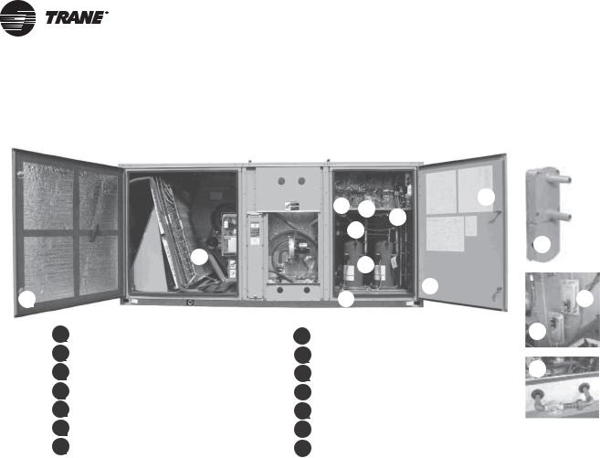
Figure 1. Factory installed options
B
A
AFoil-Faced Insulation
BQuick Adjust Idler Pulley
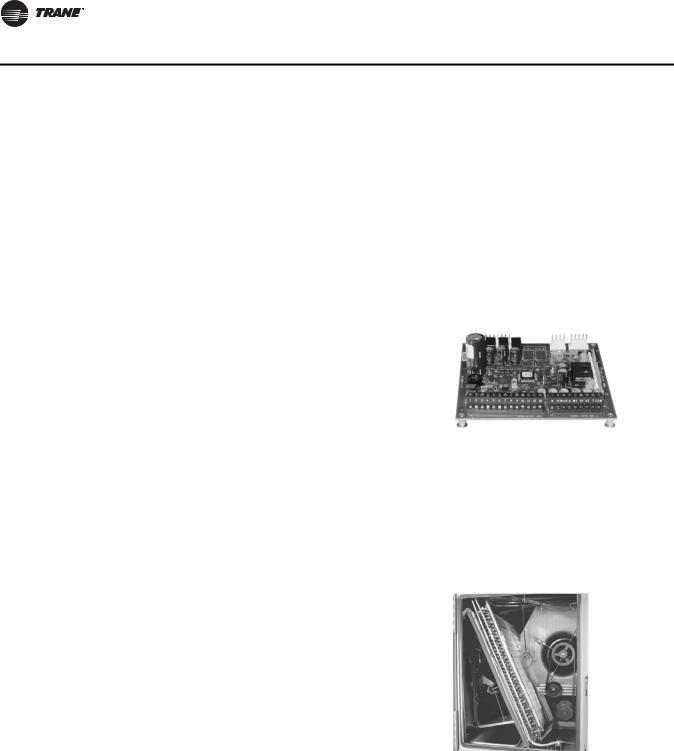
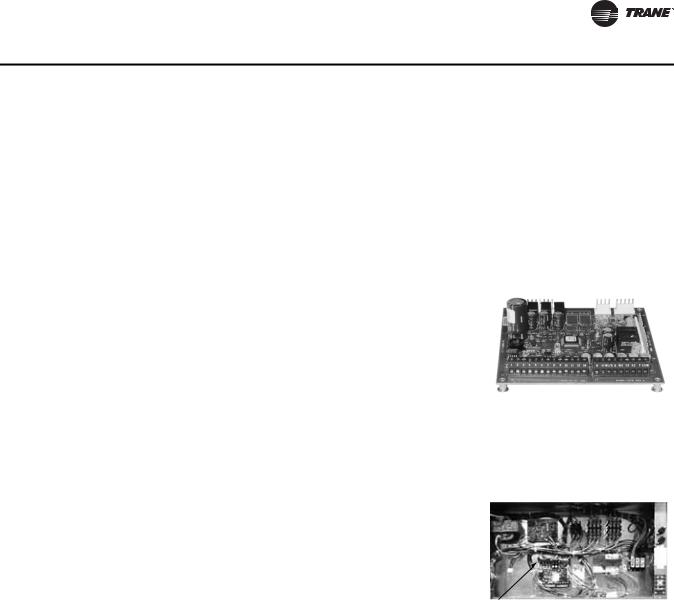
CReliaTel™ Microprocessor Controls
D Colored and Numbered Wiring
ELow Ambient Cooling to Zero° F
FHigh and Low Pressure Switches
G Scroll Compressors (R-410A)
J
CE
|
F |
|
|
|
D |
|
|
|
|
K |
|
|
G |
|
|
|
I |
|
|
|
H |
M |
|
|
Available in R-410A refrigerant |
L |
|
H |
|||
|
IHinged Access Doors
J |
Single Side Service |
N |
|
||
|
Smoke Detector |
|
K |
|
LFan Failure Switch
M |
Clogged Filter Switch |
|
Through-the-Base Gas Piping |
N |
Standard Features
•2” throwaway filters provided on 15–25 ton units
•Anti-Short Cycle Timer
•Belt Drive Motors
•Colored and Numbered Wiring
•Crankcase Heaters
•Dedicated Airflow
•Discharge Line Thermostat
•Easy Access Low Voltage Terminal Board (LTB)
•Foil-Faced and Edge Captured Insulation
•High Efficiency Drum and Tube Heat Exchanger
•High Efficiency Gas Heat with Hot Surface Ignition
•High Pressure Cutout
•IAQ Sloped Condensate Drain Pan
•Liquid Line Refrigerant Drier
•Low Ambient Cooling to 0°F
•Microchannel Type Condenser Coils (Major Design Sequence F, T and Y Units Only)
•Operating Charge of R-410A
•Patented Hybrid Condenser Coil for Easy cleaning
•Phase Monitor
•Provisions for Through-the-Base Gas and Condensate Drain Connections
•Quick Access Panels
•Quick Adjust Idler Arm Pulley
•ReliaTel™ Microprocessor Controls
4 |
RT-PRC034-EN |

Features and Benefits
•Single Point Power
•Single Side Service
•Standardized Components
•Trane Built Scroll Compressors
•U-shaped Airflow Pattern
Options
Factory Installed Options*10
•2" MERV 8 or MERV 13 Filters with Filter Removal Tool
•Black Epoxy Pre-Coated Coils4, 11
•CO2 Sensor Wiring (Wiring Only)
•Complete Coat™ Microchannel Condenser Coil
•Condensate Overflow Switch
•Hinged Access Doors
•Stainless Steel Drain Pan
•Stainless Steel Heat Exchanger with 10 year warranty4
•Through the Base Electrical Access
•Through the Base Electrical with Circuit Breaker8, 9
•Through the Base Electrical with Disconnect Switch5, 8, 9
Factory* or Field Installed Options10
Note: *Some Factory Installed Options (FIOPS) available for Downflow Air Discharge units only. Please verify with ordering system for availability.
Explanation of Notes 1–10 located on page 23 following Model Number Description.
•Clogged Filter/Fan Failure Switch2, 4
•Discharge Air Sensing Kit2, 4
•Economizer - Downflow
•Electric Heaters4, 6, 9
•Frostat2, 4
•LonTalk® Communications Interface (LCI)4
•ReliaTel™ Options Module7
•Trane Communications Interface (TCI)1, 4
Field Installed Options
•Barometric Relief
•CO2 Sensor
•Digital Display Zone Sensor
•Economizer - Horizontal
•High and Low Static Drive Kits
•LP Conversion Kit
•Manual Outside Air Damper
•Motorized Outside Air Dampers
•Oversized Motors
•Reference or Comparative Enthalpy3, 4
•Remote Potentiometer
•Roof Curb (Downflow Only)
•Thermostat
•Tool-less Hail Guards
•Ventilation Override Accessory2
•Zone Sensors and Remote Zone Sensors
RT-PRC034-EN |
5 |
Features and Benefits
Other Benefits
•Cabinet Design Ensures Water Integrity
•Ease of Service, Installation and Maintenance
•Mixed Model Build Enables “Fastest in the Industry” Ship Cycle Times
•Outstanding Airflow Distribution
•ReliaTel™ Controls benefits
•Rigorous Testing
•Unmatched Product Support
•Varitrac
Standard Features
Anti-Short Cycle Timer (Standard with ReliaTel™)
Provides a 3 minute minimum “ON” time and 3 minute “OFF” time for compressors to enhance compressor reliability by assuring proper oil return.
Colored And Numbered Wiring
Save time and money tracing wires and diagnosing the unit.
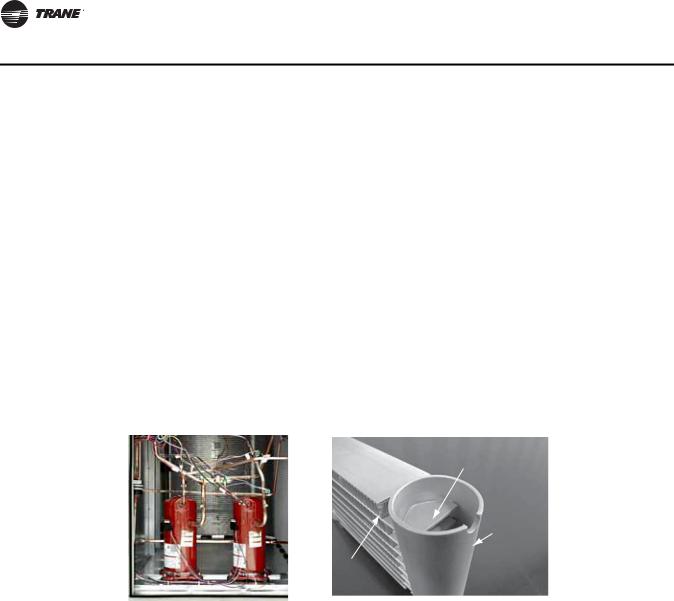
Compressors |
Microchannel Condenser Coil |
|
Microchannel Flat Tube |
|
Header |
|
(top removed) |
|
Ribbon Fin |
Voyager contains the best compressor technology available to achieve the highest possible performance.
Dual compressors are outstanding for humidity control, light load cooling conditions and system back-up applications. Dual compressors are available on all models.
Microchannel coils have better heat transfer performance due to flat streamlined tubes with small ports, and metallurgical tube-to-fin bond.
Microchannel condenser coil can reduce system refrigerant charge by up to 50% (potential LEED credit) because of smaller internal volume, which can lead to better compressor reliability. Compact all aluminum microchannel coils also help to reduce the unit weight. All-aluminum construction improves recyclability. Galvanic corrosion is also minimized due to all aluminum construction. Strong aluminum brazed structure provides better fin protection.
6 |
RT-PRC034-EN |
Features and Benefits
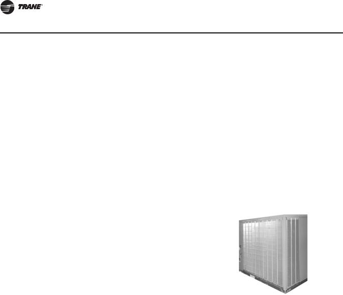
Condenser Coil
Voyager boasts a patentpending 1+1+1 condenser coil, permanently gapped for easy cleaning.
Controls—ReliaTel
ReliaTel™ microprocessor controls provide unit control for heating, cooling and ventilating utilizing input from sensors that measure indoor and outdoor temperature and other zone sensors. ReliaTel also provides outputs for building automation systems and expanded diagnostics.
For a complete list of ReliaTel offerings, refer to “Other Benefits,” p. 12.
Conversionless Units
The dedicated design units (either downflow or horizontal) require no panel removal or alteration time to convert in the field—a major cost savings during installation. Horizontal units come complete with duct flanges so the contractor doesn’t have to field fabricate them. These duct flanges are a time and cost saver.
Crankcase Heaters
These band heaters provide improved compressor reliability by warming the oil to prevent migration during off-cycles or low ambient conditions. These are standard on all Voyager models.
Discharge Line Thermostat
A bi-metal element discharge line thermostats installed as a standard option on the discharge line of each system. This standard option provides extra protection to the compressors against high discharge temperatures in case of loss of charge, extremely high ambient and other conditions which could drive the discharge temperature higher.
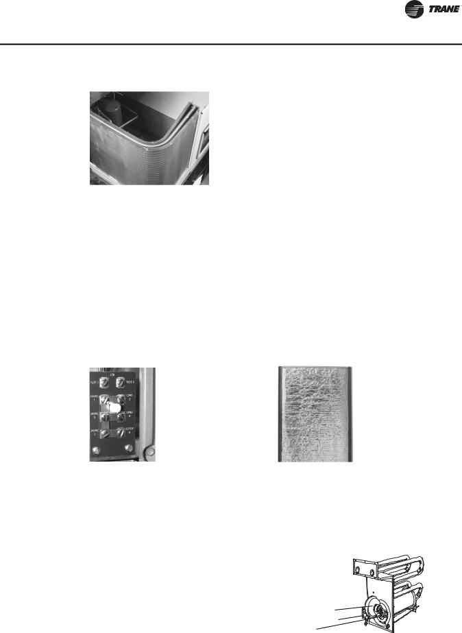
Easy Access Low Voltage Terminal Board Foil Faced Insulation
Voyager’s Low Voltage Terminal Board is external to the electrical control cabinet. It is extremely easy to locate and attach the thermostat wire and test operation of all unit functions. This is another cost and time saving installation feature.
All panels in the evaporator section of the unit have cleanable foil-faced insulation. All edges are either captured or sealed to ensure no insulation fibers get into the airstream.
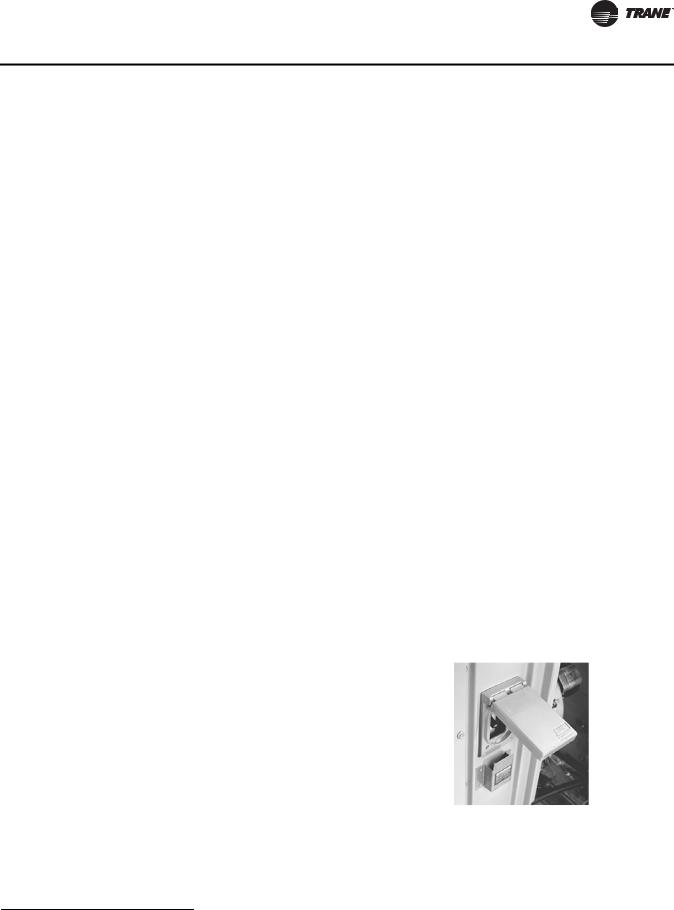
Heat Exchanger—Drum and Tube
The cabinet (pictured right) features a drum and tube heat exchanger that is manufactured using aluminized steel with stainless steel components for maximum durability.
The requirement for cycle testing of heat exchangers is 10,000 cycles by ANSI Z21.47. This is the standard required by both UL and AGA for cycle test requirements.
Forced Combustion Blower
Negative Pressure Gas Valve
Hot Surface Ignitor
RT-PRC034-EN |
7 |
Features and Benefits
The drum and tube design has been tested and passed over 150,000 cycles, which is over 15 times the current ANSI cycling requirements. The negative pressure gas valve will not allow gas flow unless the combustion blower is operating. This is one of our unique safety features.
The forced combustion blower supplies pre-mixed fuel through a single stainless steel burner screen into a sealed drum where ignition takes place. It is more reliable to operate and maintain than a multiple burner system.
The hot surface ignitor is a gas ignition device which doubles as a safety device utilizing a continuous test to prove the flame. The design is cycle tested at the factory for quality and reliability. Our gas/electric rooftops exceed all California seasonal efficiency requirements and perform even better than the California NOx emission requirements.
Low Ambient Cooling
All Voyager microprocessor units have cooling capabilities down to 0°F as standard.
Low Voltage Connections
The wiring of the low voltage connections to the unit and the zone sensors is as simple as 1-1, 2-2, and 3-3. This simplified system makes it easy for the installer to wire.
Motors
All indoor fan motors are belt drive as standard.
Pressure Cutouts
Low and high pressure cutouts are standard on all Voyager models.
Phase Monitor
The Phase Monitor is a three-phase line monitor module that protects against phase loss, phase reversal and phase unbalance. It is intended to protect compressors from reverse rotation. It has an operating input voltage range of 190–600 Vac, and LED indicators for ON and FAULT. There are no field adjustments and the module will automatically reset from a fault condition.
Quick-Access Panels
Remove three or more screws for access to the standardized internal components and wiring.
Quick-Adjust Slider Plate
With the Quick-Adjust Slider Plate, the belt and sheaves can be quickly adjusted without moving the mounted fan motor. The result is a major savings in time and money.
Single Point Power
A single electrical connection powers the unit.
Single Side Service
Single side service is standard on all units.
Sloped Drain Pans
Every Voyager unit has a non-corrosive, sloped drain pan made of pre-painted steel and standard on all units.
8 |
RT-PRC034-EN |
Features and Benefits
Standardized Components
Components are placed in the same location on all Voyager units. Familiarize yourself with one Voyager and you are familiar with every Voyager.
Due to standardized components throughout the Voyager line, contractors/owners can stock fewer parts.
Through the Base Condensate
Every unit includes provisions for through the base condensate drain connections. This allows the drain to be connected through the roof curb instead of a roof penetration.
Variety of Options1
Factory Installed Options
Black Epoxy Pre-Coated Coils (W Units Only)
The pre-coated coils are an economical option for protection in mildly corrosive environments.
Circuit Breaker (Required with Through-the-Base Electrical)
This option is a factory installed thermal magnetic, molded case, HACR Circuit Breaker with provisions for through the base electrical connections. Available on all models.
CO2 Sensor Wiring
This is the unit wiring for field installed C02 sensors. Factory-installed C02 sensor wiring saves time and ensures proper unit connections for the field installed C02 sensor kits.
Complete Coat™ Condenser Coil (T/Y Units Only)
The cathodic epoxy type electrodisposition coating is formulated for high edge build to a number of different types of heat exchangers. The coating is selected to provide excellent resistance and durability to corrosive effects of alkalies, acids, alcohols, petroleum, seawater, salt air, and corrosive environments. This coating shall be available on microchannel condenser coils.
Condensate Overflow Switch
A condensate overflow switch is available to shut the unit down in the event that the condensate drain line becomes clogged. This option protects the unit from water overflowing from the drain pan and entering the base of the units.
Disconnect Switch (Required with
Through-the-Base Electrical)
Factory installed three-pole, molded case, disconnect switch with provisions for through the base electrical connections are available. Available on all models.
Codes require a method of assured unit shutdown for servicing. Field-installed disconnects sometimes interfere with service access. Factory installation of unit disconnects reduces costs, assures proper mounting and provides the opportunity to upgrade to unit circuit breaker protection.
1 Refer to Model Number Description for option availability.
RT-PRC034-EN |
9 |
Features and Benefits
High Efficiency Filtration
Voyager units offer a variety of high efficiency filtration options. MERV 8 and MERV 13 filters provide additional filtration beyond the capabilities of typical 2” throwaway filters. Also, when MERV 8 or MERV 13 filters are ordered, units come equipped with a filter removal tool.
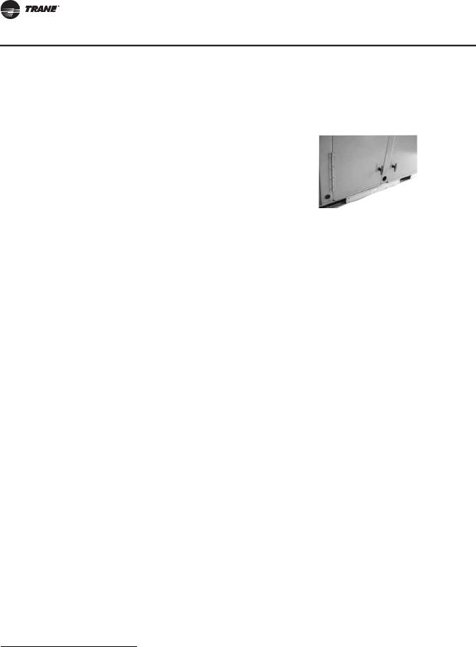
Hinged Access Doors
These doors permit easy access to the filter, fan/heat, and compressor/control sections. They reduce the potential roof damage from screws or sharp access door corners.
Stainless Steel Drain Pan
For excellent corrosion and oxidation resistance, the optional stainless steel drain pan provides a cleanable surface that complement other IAQ solutions such as high efficiency filtration (MERV 8 or 13), or demand control ventilation (CO2).
Stainless Steel Heat Exchanger
The optional stainless steel heat exchanger is constructed of 304 stainless steel. It is resistant to corrosion and oxidation and easy to clean. The high strength to weight ratio allows for high ventilation rates with gas units. With this option, a 10-year stainless steel heat exchanger warranty is standard.
Through-the-Base Electrical Utility Access
An electrical service entrance shall be provided allowing electrical access for both control and main power connections inside the curb and through the base of downflow units, and through the front of horizontal units. Option will allow for field installation of liquid-tight conduit and an external field installed disconnect switch.
Factory provided through the base openings simplify wiring and piping. Because these utility openings frequently minimize the number of roof penetrations, the integrity of roofing materials is enhanced.
Factory or Field Installed Options1
Clogged Filter/Fan Failure Switch
A dedicated differential pressure switch is available to achieve active fan failure indication and/or clogged filter indication.
These sensors allow a zone sensor service light or Integrated Comfort System to indicate a dirty filter or a fan that’s not working. The field installation charges for these valuable feedback devices often eliminate them from consideration. Factory installation can make such features a good investment.
Discharge Air Sensing Kit
Provides true discharge air sensing in heating models. The kit is functional only with the ReliaTel™ Options Module.
Economizer - Downflow
Economizers are equipped with either dry bulb or reference or comparative enthalpy sensing. These economizers provide free cooling as the outdoor temperature and/or humidity decreases. Correctly installed, they offer a valuable energy savings.
1 Refer to Model Number Description for option availability.
10 |
RT-PRC034-EN |
Features and Benefits
Electric Heaters
Electric heat modules are available within the basic unit. If ordering the Through the Base Electrical option with an Electrical Heater, the heater must be factory installed.
Frostat™
This capillary bulb embedded in the face of the evaporator coil monitors coil temperature to prevent evaporator icing and protect the compressor. Recommended for applications with low leaving air temperatures, low airflow and or high latent load applications.
LonTalk® Communications Interface
The LonTalk communications interface allows the unit to communicate as a Tracer™LCI-V device or directly with generic LonTalk Network Building Automation System Controls.
Motors
Factory or field installed oversized motors available for high static applications are available.
Oversized Motors
Factory or field installed oversized motors available for high static applications.
Reference or Comparative Enthalpy
Measures and communicates humidity while maximizing comfort control.
Trane Communication Interface (TCI)
Available factory or field installed. This module when applied with the ReliaTel™ easily interfaces with Trane’s Integrated Comfort™ System.
*Refer to Model Number Description for option availability.
Field Installed Options1
Barometric Relief
Designed to be used on downflow units, barometric relief is an unpowered means of relieving excess building pressure.
CO2 Sensor - Demand Control Ventilation (DCV)
Demand-controlled ventilation (DCV) is a control strategy that responds to the actual demand (need) for ventilation by regulating the rate at which the HVAC system brings outdoor air into the building. A CO2 sensor measures the concentration (parts per million, ppm) of CO2 (Carbon Dioxide) in the air. As the CO2 concentration changes, the outside air damper modulates to meet the current ventilation needs of the zone. The CO2 sensor kit is available as a field installed accessory.
Note: Choose factory-installed CO2 sensor wiring option to save time and ensure proper unit connections for the field installed CO2 sensor kits.
Dampers
0–25 percent manual or 0–50 percent motorized outside air dampers are available.
Digital Display Zone Sensor
The Digital LCD (Liquid Crystal Display) zone sensor has the look and functionality of standard zone sensors. This sensor should be utilized with ReliaTel™ controls.
1 Refer to Model Number Description for option availability.
RT-PRC034-EN |
11 |
Features and Benefits
Economizer - Horizontal
Economizers are equipped with either dry bulb or reference or comparative enthalpy sensing. These economizers provide free cooling as the outdoor temperature and/or humidity decreases. Correctly installed, they offer a valuable energy savings.
High Static Drive
Available on many models, this high static drive accessory extends the capability of the standard motor. Avoid expensive motors and operating costs by installing this optimized sheave accessory.
LP Conversion Kit
Provided for field conversion of gas/electric units from Natural gas to Propane.
Remote Potentiometer
When properly installed in the economizer control circuitry, this accessory provides a remote variable resistance to enable the operator to adjust the minimum damper position.
Roof Curbs
Available for downflow units. Only two roof curbs for the entire Voyager line simplifies curb selection.
Tool-less Hail Guards
Tool-less, hail protection quality coil guards shall be field-installed for condenser coil protection. This option protects the condenser coil from vandalism and/or hail damage.
Ventilation Override Accessory
With the Ventilation Override Accessory installed, the unit can be set to transition to up to three different preprogrammed sequences for Smoke Purge, Pressurization, and Exhaust. The transition occurs when a binary input on the RTOM is closed (shorted). This would typically be a hard wired relay output from a smoke detector or fire control panel.
Zone Sensors/Thermostats
Available in programmable, automatic and manual styles.
Note: Zone sensor required for units configured for Single Zone VAV indoor fan system control to enable Single Zone VAV functionality.
Other Benefits
Airflow Distribution
Airflow is outstanding. The Voyager can replace an older machine with old ductwork and, in many cases, improve the comfort through better air distribution. The U-shaped airflow allows for improved static capabilities.
Cabinet Integrity
For added water integrity, Voyager has a raised 1 1/8” lip around the supply and return of the downflow units to prevent water from blowing into the ductwork.
12 |
RT-PRC034-EN |
Features and Benefits
Easy to Install, Service and Maintain
Because today’s owners are very cost-conscious when it comes to service and maintenance, the Trane Voyager was designed with direct input from service contractors. This valuable information helped to design a product that would get the serviceman off the job quicker and save the owner money. Voyager does this by offering outstanding standard features enhanced by a variety of factory and field installed options, multiple control options, rigorously tested proven designs and superior product and technical support.
Outstanding Airflow Distribution
Airflow is outstanding. The Voyager can replace an older machine with old ductwork and, in many cases, improve the comfort through better air distribution.
ReliaTel Controls Benefits
ReliaTel™ controls provide unit control for heating, cooling and ventilating utilizing input from sensors that measure outdoor and indoor temperature.
ReliaTel Control Logic Enhances Quality and Reliability
–prevents the unit from short cycling, considerably improving compressor life.
–ensures that the compressor will run for a specific amount of time which allows oil to return for better lubrication, enhancing the reliability of the compressor.
Voyager with ReliaTel™ reduces the number of components required to operate the unit, thereby reducing possibilities for component failure.
ReliaTel Makes Installing and Servicing Easy
ReliaTel™ eliminates the need for field installed antishortcycle timer and time delay relays. ReliaTel™ controls provide these functions as an integral part of the unit. The
contractor no longer has to purchase these controls as options and pay to install them. The wiring of the low voltage
connections to the unit and the zone sensors is as easy as 1-1,
ReliaTel™
2-2, and 3-3. This simplified system makes wiring easier for the installer.
ReliaTel Makes Testing Easy
ReliaTel™ requires no special tools to run the Voyager unit through its paces. Simply place a jumper between Test 1 and Test 2 terminals on the Low Voltage Terminal Board and the unit will walk through its operational steps automatically.
The unit automatically returns control to the zone sensor after stepping through the test mode a single time, even if the jumper is left on the unit.
As long as the unit has power and the “system on” LED is lit, ReliaTel is operational. The light indicates that the controls are functioning properly.
ReliaTel features expanded diagnostic capabilities when utilized with Trane Integrated Comfort™ Systems.
Some zone sensor options have central control panel lights which indicate the mode the unit is in and possible diagnostic information (dirty filters for example).
Other ReliaTel Benefits
The ReliaTel™ built-in anti-shortcycle timer, time delay relay and minimum “on” time control functions are factory tested to assure proper operation.
RT-PRC034-EN |
13 |
Features and Benefits
ReliaTel softens electrical “spikes” by staging on fans, compressors and heaters.
Intelligent Fallback is a benefit to the building occupant. If a component goes astray, the unit will continue to operate at predetermined temperature setpoint.
Intelligent Anticipation is a standard ReliaTel feature. It functions continuously as ReliaTel and zone sensor(s) work together in harmony to provide much tighter comfort control than conventional electro-mechanical thermostats.
The same ReliaTel Board fits all Voyager Packaged Gas/Electrics, Cooling, and Heat Pump models. This provides standardization of parts for contractors. Less money is tied up in inventory with ReliaTel.
Rigorous Testing
All of Voyager’s designs were rigorously rain tested at the factory to ensure water integrity. Actual shipping tests were performed to determine packaging requirements. Units were test shipped around the country to determine the best packaging. Factory shake and drop tests were used as part of the package design process to help assure that the unit arrives at the job site in top condition. Rigging tests include lifting a unit into the air and letting it drop one foot, assuring that the lifting lugs and rails hold up under stress.
The evaporator and condenser coils are leak tested at 225 psig and pressure tested to 450 psig. All parts are inspected at the point of final assembly. Sub-standard parts are identified and rejected immediately.
Every unit receives a 100 percent unit run test before leaving the production line to make sure it lives up to rigorous Trane requirements. Voyager units incorporate either a one piece top or the Trane-Tite-Top (T3). Each part of the top (either two or three pieces) overlaps in such a way that water cannot leak into the unit. These overlapped edges are gasketed and sealed to ensure superior water integrity.
Unmatched Support
Trane Sales Representatives are a Support Group that can assist you with:
•Product
•Application
•Service
•Training
•Special Applications
•Specifications
•Computer Programs and much more
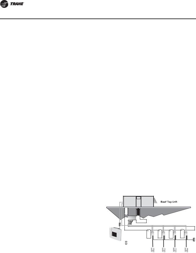
VariTrac—Building Automation
System
When Trane’s changeover VAV System for light commercial applications is coupled with Voyager, it provides the latest in technological advances for comfort management systems and can allow thermostat control in every zone served by VariTrac.
|
|
|
|
|
|
|
|
|
14 |
|
|
|
|
|
RT-PRC034-EN |
||

Application Considerations
Application of this product should be within the cataloged airflow and cooling considerations.
Barometric Relief
This product line offers an optional barometric relief damper for use in conjunction with economizer option. This accessory consists of gravity dampers which open with increased pressure. As the building air pressure increases, the pressure in the unit return air section also increases, opening the dampers and relieving the conditioned space.
Notes:
•The effectiveness of barometric relief damper during economizing operation is system related.
•Pressure drop of the return air system should be considered to control building pressurization.
Black Epoxy Coil
The coils are manufactured with a thermoset, vinyl coating that is bonded to the aluminum fin stock prior to the fin stamping process. These coils are an economical option for protection in mildly corrosive environments.
Note: Not to be used where seacoast applications exist.
Clearance Requirements
The recommended clearances identified with unit dimensions should be maintained to ensure adequate serviceability, maximum capacity and peak operating efficiency. Actual clearances which appear inadequate should be reviewed with the local Trane sales personnel.
Complete Coat™ Microchannel Condenser Coil
The cathodic epoxy type electrodisposition coating is formulated for high edge build to a number of different types of heat exchangers. The coating is selected to provide excellent resistance and durability to corrosive effects of alkalies, acids, alcohols, petroleum, seawater, salty air and other corrosive environments. This coating shall be available on microchannel condenser coils.
Condensate Trap
The evaporator is a draw-thru configuration. A trap must be field provided prior to start-up on the cooling cycle.
Heating Operation
The heat exchanger is manufactured with aluminized steel. To prevent condensation within the heat exchanger, do not exceed 50 percent outside air or a minimum mixed air temperature of 40°F.
Optional Stainless Steel Heat Exchanger
The optional stainless steel heat exchanger is manufactured with 304 stainless steel. To prevent corrosion and prolong heat exchanger reliability, the minimum mixed air temperature allowed across the heat exchanger is 20°F.
Low Ambient Cooling
The Voyager™ line features, with ReliaTel™ microprocessor controls, low ambient cooling down to 0°F. The following options need to be included/considered when low ambient applications are required: continuous fan operation, crankcase heaters (standard), thermal expansion valves, frostat.
Contact your local Trane Representative for more assistance with low ambient cooling applications.
Unit Pitch
These units have sloped condensate drain pans. Units must be installed level. Any unit slope must be toward access side of the unit.
RT-PRC034-EN |
15 |

Selection Procedure (SI/IP)
SI Selection Procedure
Cooling Capacity
Note: Cooling Capacity Procedure is the same for cooling (TS*), gas/electric (YS*) and heat pump (WS*) units.
Step 1.
Calculate the building’s total and sensible cooling loads at design conditions. Use the Trane calculation methods or any other standard accepted method.
Factors used in unit selection:
•Total Cooling Load: 40.0 kW
•Sensible Cooling Load: 29.0 kW
•Airflow: 8500 m3/h
•Electrical Characteristics: 380-415/50/3
•Summer Design Conditions:
•Entering Evaporator Coil: 27°C DB, 22°C WB,
35°C Outdoor Ambient
•External Static Pressure: 127 Pa
•Rooftop—downflow configuration accessories
•Roof Curb
•Economizer
•Electric Heat
Step 2.
Size the equipment using Table 4, p. 30. Match the cooling loads at design conditions.
Table 4, p. 30 shows that a TSD155F has a gross cooling capacity of 47.5 kW and 35.6 kW sensible capacity at 8500 m3/h and 35°C DB outdoor ambient with 27°C DB, 19°C WB air entering the evaporator.
To Find Capacity at Intermediate Conditions Not in the Table:
When the design conditions are between two numbers that are in the capacity table, interpolation is required to approximate the capacity.
Note: Extrapolation outside of the table conditions is not recommended.
16 |
RT-PRC034-EN |
Selection Procedure (SI/IP)
Step 3.
In order to select the correct unit which meets the building’s requirements, the fan motor heat must be deducted from the gross cooling capacity. The amount of heat that the fan motor generates is dependent on the effort by the motor, airflow and static pressure. To determine the total unit static pressure (see Table 48, p. 56 for Static Pressure Drops Through Accessories):
External Static Duct System |
127 Pa |
Standard Filter 25mm |
19 Pa |
Economizer (100% OA) |
12 Pa |
Electric Heater Size 27 kW |
11Pa |
Total Static Pressure |
169 Pa |
Notes:
1.Reference “Heating Capacity” section on this page for determination of heater size.
2.No additional static add for gas/heat exchanger.
Note: The Evaporator Fan Performance (see Table 20, p. 44) has already accounted for the pressure drop for standard filters and wet coils (see note below Table 20, p. 44). Therefore, the actual total static pressure is 169 - 19 (from Table 48, p. 56) = 150 Pa.
With 8500 m3/h and 150 Pa. Table 20, p. 44 shows 1.12 kW for this unit. The formula below can be used to calculate Fan Motor Heat:
Fan Motor Heat = 1.23 * Fan Power (kW) 1.23 * 1.12 kW = 1.3776 kW
Now subtract the fan motor heat from the gross cooling capacity of the unit:
Net Total Cooling Capacity = 47.5 - 1.37 = 46.12
Net Sensible Cooling Capacity = 35.6 - 1.37 = 34.22
Step 4.
If the performance will not meet the required load of the building, total or sensible cooling load, try a selection at the next higher size unit.
Heating Capacity
Note: Heating capacity procedures DIFFER for cooling (TS*), gas/electric (YS*) and heat pump (WS*) units.
Step 1.
Calculate the building heating load using the Trane calculation form or other standard accepted method.
Step 2.
Size the system heating capacity to match the calculated building heating load. The following are building heating requirements:
TS* cooling units:
•380 volt/three-phase Power Supply
•Total heating load of 20.5 kW
•Airflow of 8500 m3/h
The electric heat accessory capacities are listed in Table 52, p. 62. From the table, a 26.9 kW heater at 415 volts is selected. In order to determine capacity at 380 volts, the heater voltage correction
RT-PRC034-EN |
17 |

Selection Procedure (SI/IP)
factor from Table 53, p. 62 must be used. Therefore, 26.9 kW x 0.84 (voltage correction factor) = 22.59 kW.
YS* gas/electric:
The fuel used is natural gas with a total heating load of 30 kW. Table 2, p. 26 shows 61.1 kW and 85.5 kW input models. The output capacities of these furnaces are 49.6 kW and 69.4 kW, respectively. The low heat model with 49.6 kW output best matches the building requirements.
WS* heat pumps:
Total heating load of 30.0 kW. Outdoor ambient (Winter) of -9°C DB and indoor return of 21°C DB and an airflow of 8500 m3/h. The unit is using a 380 V power supply. Use the integrated portion of Table 16, p. 42 for the WC*155 to determine capacity at winter design conditions. The mechanical heating portion of the heat pump will provide 20.9 kW.
Step 3.
Note: This step does not apply to TS* and YS* units.
WS* heat pumps:
Because 22.1 kW is less than the building's required heating capacity at winter design condition, a supplementary heater must be selected.
30.0 - 20.9 = 9.1 kW
From Table 62, p. 64, a 13.4 kW heater at 415 V is selected. To find the capacity at 380 V, the heater voltage correction factor from Table 63, p. 64 must be used. Therefore, 13.4 kW x 0.84 (voltage correction factor) = 11.26 kW. This heater will be adequate to do the job.
Air Delivery Selection
Note: Air Deliver procedures is the same for cooling (TS*), gas/electric (YS*) and heat pump (WS*) units.
External static pressure drop through the air distribution system has been calculated to be 150 Pa. From Table 48, p. 56, static pressure drop through the economizer is 12 Pa and the 27 kW heater is 12 Pa (127 + 12 + 12). Enter (Table 20, p. 44) for a TSD155F at 8500 m3/h and 150 Pa static pressure.
The standard motor at 566 rpm will give the desired airflow at a rated kW of 1.12.
18 |
RT-PRC034-EN |

Selection Procedure (SI/IP)
IP Selection Procedure
Cooling Capacity
Note: Cooling Capacity Procedure is the same for cooling (TS*), gas/electric (YS*) and heat pump (WS*) units.
Step 1.
Calculate the building’s total and sensible cooling loads at design conditions. Use the Trane calculation methods or any other standard accepted method.
Factors used in unit selection:
•Total Cooling Load: 140 MBh
•Sensible Cooling Load: 100 MBh
•Airflow: 5000 cfm
•Electrical Characteristics: 380-415/50/3
•Summer Design conditions:
•Entering Evaporator Coil: 80 DB, 73 WB
•Outdoor Ambient: 95 DB
•External Static pressure: 0.50 in. wg
•Rooftop - downflow configuration
•Accessories
• Roof Curb
• Economizer
• Electric Heat
Step 2.
As a starting point, a rough determination must be made of the size of the unit. The final selection will be made after examining the performance at the given conditions. Divide the total cooling load by nominal Btu/h per ton (12 MBh per ton); then round up to the nearest unit size.
140 MBh / 12 MBh = 11.6 tons
Step 3.
Table 5, p. 31 shows that a TSD155F has a gross cooling capacity of 162.2 MBh and 121.4 MBh sensible capacity at 5000 cfm and 95 DB outdoor ambient with 80 DB, 73 WB air entering the evaporator.
To Find Capacity at Intermediate Conditions Not in the Table:
When the design conditions are between two numbers that are in the capacity table, interpolation is required to approximate the capacity.
Note: Extrapolation outside of the table conditions is not recommended.
RT-PRC034-EN |
19 |
Selection Procedure (SI/IP)
Step 4.
In order to select the correct unit which meets the building’s requirements, the fan motor heat must be deducted from the gross cooling capacity. The amount of heat that the fan motor generates is dependent on the effort by the motor, cfm and static pressure. To determine the total unit static pressure you add the external static pressure to the additional static related by the added features (see Table 49, p. 57 for Static Pressure Drops Through Accessories):
External Static Duct System |
0.50 wg |
Standard Filter 1in. |
0.08 wg |
Economizer (100% OA) |
0.05 wg |
Electric Heater Size 27 kW |
0.05 wg |
Total Static Pressure |
0.68 wg |
Notes:
1.Reference “Heating Capacity” section on this page for determination of heater size.
2.No additional static add for gas/heat exchanger.
Note: The Evaporator Fan Performance Table 21, p. 44 has already accounted for the pressure drop for standard filters and wet coils (see note below Table 21, p. 44). Therefore, the actual total static pressure is 0.68 - 0.08 (from Table 49, p. 57) = 0.60 wg.
With 5000 cfm and 0.60 wg, Table 21, p. 44 shows 1.50 bhp for this unit. The formula below can be used to calculate Fan Motor Heat:
Fan Motor Heat = 3.15 * Fan bhp 3.15 * 1.50 = 4.725 MBh
Now subtract the fan motor heat from the gross cooling capacity of the unit:
Net Total Cooling Capacity =
162.2 - 4.725 = 157.475 MBh
Net Sensible Cooling Capacity =
121.4 - 4.725 = 116.675 MBh
Step 5.
If the performance will not meet the required load of the building, total or sensible cooling load, try a selection at the next higher size unit.
20 |
RT-PRC034-EN |
Selection Procedure (SI/IP)
Heating Capacity
Note: Heating capacity procedures DIFFER for cooling (TS*), gas/electric (YS*) and heat pump (WS*) units.
Step 1.
Calculate the building heating load using the Trane calculation form or other standard accepted method.
Step 2.
Size the system heating capacity to match the calculated building heating load. The following are building heating requirements:
TS* cooling units:
380 volt/3 phase Power Supply
Total heating load of 75.0 MBh 5000 cfm
The electric heat accessory capacities are listed in Table 52, p. 62. From the table, a 26.9 kW heater will deliver 91.73 MBh at 415 volts. In order to determine capacity at 380 volts, the heater voltage correction factor from Table 53, p. 62 must be used. Therefore, 91.73 MBh x 0.84 (voltage correction factor) = 77.05 MBh.
YS* gas/electric:
Fuel natural gas and a total heating load of 115 MBh. Table 2, p. 26 shows 208.3 MBh and 291.7 MBh input models. The output capacities of these furnaces are 169.2 MBh and 236.7 MBh respectively. The low heat model with 169.2 MBh output best matches the building requirements.
WS* heat pumps:
Total heating load of 100 MBh. Outdoor ambient (Winter) of 17 DB and Indoor Return of 70 DB and an airflow of 5000 cfm. The unit is using a 380 V power supply. Use the integrated portion of Table 17, p. 42 for the WC*155 to determine capacity at winter design conditions. The mechanical heating portion of the heat pump will provide 71.2 MBh.
Step 3.
Note: This step does not apply to TS* and YS* units.
WS* heat pumps:
Because 71.2 MBh is less than the building’s required heating capacity at winter design conditions, a supplementary heater must be selected.
100 MBh - 71.2 MBh = 28.8 MBh
From Table 62, p. 64, a 13.4 kW heater at 415 V is selected. To find the capacity at 380 V, the heater voltage correction factor from Table 63, p. 64 must be used. Therefore, 13.4 kW x 0.84 (voltage correction factor) = 11.26 kW. This heater will be adequate to do the job. 38.3 MBh.
Air Delivery Selection
Note: Air Delivery procedures is the same for cooling (TS*), gas/electric (YS*) and heat pump (WS*) units.
External static pressure drop through the air distribution system has been calculated to by
0.60 inches of water. From Table 49, p. 57, static pressure drop through the economizer is 0.05 and the 26.9 kW heater is 0.05 inches of water (0.50 + 0.05 + 0.05). Enter (Table 21, p. 44) for a TSD155 at 5000 cfm and 0.60 static pressure. The standard motor at 566 rpm will give the desired airflow at a rated bhp of 1.50.
RT-PRC034-EN |
21 |

Model Number Descriptions
T |
|
S |
|
D |
1 |
5 |
5 |
|
F |
|
D |
|
R |
|
|
|
|
|
|
|
|
|
|
|
|
|
|
|
|
1 |
2 |
3 |
4 |
5 |
6 |
7 |
8 |
9 |
||||||
Digit 1 — Unit Type
T |
= |
Packaged Cooling, Electric Heat |
Y |
= |
Packaged Gas/Electric |
W= Packaged Heat Pump, Electric Heat
Digit 2 — Efficiency
S = Standard
Digit 3 — Airflow Configuration
D |
= |
Downflow |
H |
= |
Horizontal |
Digit 4, 5, 6 — Nominal Gross Cooling Capacity (MBh)
155 = 15 Tons Standard Efficiency
175 = 17½ Tons Standard Efficiency
200 = 20 Tons Standard Efficiency
250 = 25 Tons Standard Efficiency
Digit 7 — Major Design
Sequence
E= Round Tube Plate Fin Type Condenser Coils
F= Microchannel Type Condenser Coils
Digit 8 — Voltage Selection
D |
= |
380-415/50/3 |
T |
= |
200/50/311 |
Digit 9 — Unit Controls
R = Reliatel
Digit 10 — Heating Capacity
Note: |
(Applicable to Digit 1 T/W models |
|
|
|
only) |
0 |
= |
No Heat |
G |
= |
18 kW Electric Heat |
K |
= |
27 kW Electric Heat |
N |
= |
36 kW Electric Heat |
P |
= |
54 kW Electric Heat |
R |
= |
72 kW Electric Heat |
Note: |
(Applicable to Digit 1 Y models |
|
|
|
only) |
H |
= |
Gas Heat - High |
L |
= |
Gas Heat - Low |
X |
= |
Gas Heat - SS Ht Ex - Low |
Z |
= |
Gas Heat - SS Ht Ex - High |
Digit 11 — Minor Design
Sequence
Digit 12, 13 — Service Sequence
Digit 14 — Fresh Air Selection
0 = No Fresh Air
A= Manual Damper
B= Motorized Damper
D |
= |
Econ Dry Bulb w/ Barometric |
|
|
Relief |
F |
= |
Econ Reference Enthaply w/ |
|
|
Barometric Relief |
H= Econ Comparative Enthaply w/ Barometric Relief
22
Digit 15 — Supply Fan/Drive
Type/Motor
0= Standard Motor
1= Oversized Motor
3 = High Efficiency Motor
6= Single Zone Variable Air Volume Standard Motor
7= Multi-Speed Standard Motor
8= Single Zone Variable Air Volume Oversized Motor
9= Multi-Speed Oversized Motor
A= Single Zone Variable Air Volume Standard Motor w/ Shaft Ground Ring
B= Multi-Speed Standard Motor w/ Shaft Ground Ring
C= Single Zone Variable Air Volume Oversized Motor w/ Shaft Ground Ring
D= Multi-Speed Oversized Motor w/ Shaft Ground Ring
Digit 16 — Hinged Service
Access / Filters
0 |
= |
Standard Panels/Standard Filters |
A |
= |
Hinged Access/Standard Filters |
Digit 17 — Condenser Coil
Protection
0= Standard Coil
1= Standard Coil With Hail Guard
2= Black Epoxy Pre-Coated Coil
3= Black Epoxy Pre-Coated Coil With Hail guard
4= CompleteCoat™Condenser Coil
5= CompleteCoat™Condenser Coil with Hail Guard
Digit 18 — Through The Base
Provisions
0 = No Through The Base Provisions
A= Through The Base Electric
B= Through The Base Gas
C= Through The Base Electric/Gas
D= Through The Base Access
Digit 19 — Disconnect Switch/
Circuit Breaker
0= No Disconnect/circuit break
1= Unit Mounted Non-Fused Disconnect Switch
2= Unit Mounted Circuit Breaker
Digit 20 — Convenience Outlet
Option
0 = Without Convenience Outlet
A= Unpowered Convenience Outlet
B= Powered Convenience Outlet
0 |
|
A |
|
A |
|
|
|
|
|
10 |
11 |
12 |
||
Digit 21 — Communications
Options
0= Without Communications Options
6= Building Automation Control Network Communications Interface
Digit 22 — Refrigeration System Option
0 = Standard refrigeration system
Digit 23 — Refrigeration
Controls
0= Without Refrigeration Controls
1= Frostat
Digit 24 — Smoke Detector
0 = Without Smoke Detector
A= Return Air Smoke Detector
B= Supply Air Smoke Detector
C= Return/Supply Air Smoke Detector
D= Plenum Smoke Detector
Digit 25 — System Monitoring
Controls
0= No Monitoring Controls
1= Clogged Filter Switch
2= Fan Failure Switch
3= Discharge Air Sensing
4= Clogged Filter Switch and Fan Failure
5= Clogged Switch and Discharge Air Sensing
6= Fan Failure Switch and Discharge Air Sensing
7= Clogged Filter Switch, Fan Failure
Switch and Discharge Air Sensing
A= Condensate Drain Pan Overflow Switch
B= Clogged Filter Switch and Condensate Drain Pan Overflow Switch
C= Fan Failure Switch and Condensate Drain Pan Overflow Switch
D= Discharge Air Sensing and Condensate Drain Pan Overflow Switch
E= Clogged Filter Switch, Fan Failure Switch and Condensate Drain Pan Overflow Switch
F= Clogged Filter Switch, Discharge Air Sensing Tube and Condensate Drain Pan Overflow Switch
G= Fan Failure Switch, Discharge Air Sensing Tube and Condensate Drain Pan Overflow Switch
H= Clogged Filter Switch, Fan Failure Switch, Discharge Air Sensing and Condensate Drain Pan Overflow Switch
RT-PRC034-EN

Model Number Descriptions
Digit 26 - System Monitoring
Controls
0 No Monitoring Controls
A Demand Control Ventilation (CO2)12
Digit 27 - Unit Hardware
Enhancements
0No Enhancements
1Stainless Steel Drain Pan
Options
Factory Installed Options*10
•Black Epoxy Pre-Coated Coils4
•CO2 Sensor Wiring (Wiring Only)
•Complete Coat Microchannel Coil
•Condensate Overflow Switch
•Hinged Access Doors
•MERV 8 or 13 with Filter Removal Tool
•Stainless Steel Drain Pan
•Stainless Steel Heat Exchanger with 10 year warranty4
•Through the Base Electrical Access
•Through the Base Electrical with Circuit Breaker8, 9
•Through the Base Electrical with Disconnect Switch5, 8, 9
Factory* or Field Installed Options10
•Clogged Filter/Fan Failure Switch2, 4
•Discharge Air Sensing Kit2, 4
•Economizer - Downflow
•Electric Heaters4, 6, 9
•Frostat2, 4
•LonTalk® Communications Interface (LCI)4
•ReliaTel Options Module7
Field Installed Options
•Barometric Relief
•CO2 Sensing
•Digital Display Zone Sensor
•Dual Thermistor Remote Zone Sensor
•Economizer - Horizontal
•High and Low Static Drive Kits
•LP Conversion Kit
•Manual Outside Air Damper
•Motorized Outside Air Dampers
•Oversized Motors
•Reference or Comparative Enthalpy3, 4
•Remote Potentiometer
•Roof Curb (Downflow Only)
•Thermostat
•Tool-less Hail Guards
•Trane Communications Interface (TCI)1, 4
•Ventilation Override Accessory2
•Zone and Remote Zone Sensors
Model Number Notes
1.TCI is for use with non-VariTrac systems and VariTrac systems.
2.Requires ReliaTel options module.
3.Requires Economizer.
4.Available factory installed on downflow AND horizontal units. Verify with ordering system.
5.Cannot be fused.
6.Must be factory installed when using Through-the-Base Options.
7.ReliaTel Options Module is required when ordering the following accessories (Factoryor Field-Installed Options): Clogged Filter Switch, Fan Fail Switch, Discharge Air Sensing Kit, Frostat, Ventilation Override.
8.Unit mounted disconnect and circuit breakers are mutually exclusive of each other.
9.Through-the-base electrical option or Horizontal Side Access must be ordered with either unit mounted disconnect or circuit breaker. When adding heat, must order Trane Electric Heat.
10.All Factory Installed Options are Built-to-Order. Check order services for estimated production cycle.
11.Available on Heat Pump (W) units only.
12.Demand Control Ventilation Option includes wiring only. The C02 sensor is a field-installed only option.
Note: *Some Factory Installed Options (FIOPS) available for Downflow Air Discharge units only. Please verify with ordering system for availability.
RT-PRC034-EN |
23 |

General Data
Table 1. TS* general data
|
|
15–25 Tons Downflow and Horizontal Units |
|
||
|
|
|
|
|
|
Model |
TS*155FD |
TS*175FD |
TS*200FD |
TS*250FD |
|
|
|
|
|
|
|
Cooling Performance(a) |
|
|
|
|
|
ARI Gross Capacity kW (MBh) |
44.8 (153) |
51.2 (174.8) |
62.7 (214.1) |
68.3 (233.0) |
|
COP/EER(b) |
3.47 / 11.8 |
3.51 / 12.0 |
3.14 / 10.7 |
3.10 / 10.8 |
|
Nominal Airflow - m3/h (cfm) |
7480 (4400) |
9000 (5300) |
10400 (6125) |
12240 (7200) |
|
ARI Airflow - m3/h (cfm) |
44.0 (150) |
49.8 (170.0) |
61.0 (208.2) |
66.0 (225.3) |
|
ARI Net Capacity - kW (MBh) |
13 |
14.6 |
20.0 |
21.6 |
|
System Power - kW |
12.9 |
14.5 |
19.6 |
21.0 |
|
|
|
|
|
|
|
Compressor |
|
|
|
|
|
No./Type |
2/Scroll |
2/Scroll |
2/Scroll |
2/Scroll |
|
|
|
|
|
|
|
Sound Rating dB(c) |
9.0 |
9.2 |
9.2 |
9.2 |
|
Outdoor Coil - Type |
Microchannel |
Microchannel |
Microchannel |
Microchannel |
|
Coil Width mm (in.) |
25.4 (1) |
25.4 (1) |
25.4 (1) |
25.4 (1) |
|
Face Area - m2 (sq. ft.) |
3.27 (35.2) |
3.27 (35.2) |
3.27 (35.2) |
3.27 (35.2) |
|
Rows/Fins per inch |
1 / 20 |
1 / 20 |
1 / 20 |
1 / 20 |
|
|
|
|
|
|
|
Indoor Coil - Type |
Hi-Performance |
Hi-Performance |
Hi-Performance |
Hi-Performance |
|
Tube Size OD - in. |
0.3125 |
0.3125 |
0.3125 |
0.3125 |
|
Face Area - m2 (sq. ft.) |
(2.42) 26 |
(2.42) 26 |
(2.42) 26 |
(2.42) 26 |
|
Rows/Fins per inch |
3/ 15 |
4 / 15 |
4 / 15 |
4 / 15 |
|
Refrigerant Control |
Short Orifice |
Short Orifice |
Short Orifice |
Short Orifice |
|
Drain Connection No./Size - in. |
1/1.00 NPT |
1/1.00 NPT |
1/1.00 NPT |
1/1.00 NPT |
|
|
|
|
|
|
|
Outdoor Fan - Type |
Propeller |
Propeller |
Propeller |
Propeller |
|
No. Used/Diameter - mm (in.) |
2 / 660 (26) |
2 / 660 (26) |
2 / 660 (26) |
2 / 710(28) |
|
Drive Type/No. Speeds |
Direct / 1 |
Direct / 1 |
Direct / 1 |
Direct / 1 |
|
Airflow - m3/h (cfm) |
15630 (9200) |
18860 (11100) |
18000 (10600) |
19880 (11700) |
|
No. Motors/Power - W (HP) |
2 / 250(0.33) |
2 / 560(0.75) |
2 / 560(0.75) |
2 / 560(0.75) |
|
Motor RPM |
925 |
950 |
950 |
950 |
|
|
|
|
|
|
|
Indoor Fan - Type |
FC Centrifugal |
FC Centrifugal |
FC Centrifugal |
FC Centrifugal |
|
No. Used |
1 |
1 |
1 |
1 |
|
Diameter x Width - mm (in.) |
457x457 (18x18) |
457x457 (18x18) |
457x457 (18x18) |
457x457 (18x18) |
|
Drive Type/No. Speeds |
Belt / 1 |
Belt / 1 |
Belt / 1 |
Belt / 1 |
|
No. Motors |
1 |
1 |
1 |
1 |
|
Standard/Oversized Motor Power — |
1500(2.0) / 2200(3.0) |
2200(3.0) / 3700(5.0) |
2200(3.0) / 3700(5.0) |
3700(5.0) / N/A |
|
W (HP) |
|||||
|
|
|
|
||
Motor RPM - Standard/Oversized |
1450 / 2850 |
2850 / 2920 |
2850 / 2920 |
2920/N/A |
|
|
|
|
|
|
|
24 |
RT-PRC034-EN |

General Data
TS* General Data
Table 1. TS* general data (continued)
|
|
15–25 Tons Downflow and Horizontal Units |
|
||
|
|
|
|
|
|
Model |
TS*155FD |
TS*175FD |
TS*200FD |
TS*250FD |
|
|
|
|
|
|
|
Filters—Type/Furnished |
|
|
|
|
|
Type Furnished |
Throwaway |
Throwaway |
Throwaway |
Throwaway |
|
Number Size Recommended |
|
|
|
|
|
Downflow—mm |
(4)508x508x50 |
(4)508x508x50 |
(4)508x508x50 |
(4)508x508x50 |
|
(4)508x635x50 |
(4)508x635x50 |
(4)508x635x50 |
(4)508x635x50 |
||
|
|||||
Downflow—in |
(4)20x20x2 (4)20x25x2 |
(4)20x20x2 (4)20x25x2 |
(4)20x20x2 (4)20x25x2 |
(4)20x20x2 (4)20x25x2 |
|
Horizontal—mm |
(8)508x635x50 |
(8)508x635x50 |
(8)508x635x50 |
(8)508x635x50 |
|
Horizontal—in |
(8)20x25x2 |
(8)20x25x2 |
(8)20x25x2 |
(8)20x25x2 |
|
|
|
|
|
|
|
Refrigerant Charge |
5.2/2.7 (11.4/6) |
6.5/3.4 (14.4/7.6) |
6.1/3.2 (13.5/7) |
4.8/4.8 (10.5/10.5) |
|
R-410A kg (lb)(d) |
|||||
|
|
|
|
||
(a)Cooling Performance is rated at 35°C (95°F) ambient, 26.7°C (80°F) entering dry bulb, 19.4°C (67°F) entering wet bulb. Gross capacity does not include the effect of fan motor heat. ARI capacity is net and includes the effect of fan motor heat. Units are suitable for operation ±20% of nominal airflow. Ratings shown are tested and certified in accordance with ARI Standard 210/240 or 340/360 certification program.
(b)EER is rated at ARI conditions and in accordance with DOE test procedures.
(c)Sound Ratings shown are tested in accordance with ARI Standard 270 or 370.
(d)Refrigerant charge is an approximate value. For a more precise value, see unit nameplate and service instructions.
RT-PRC034-EN |
25 |

General Data
|
|
|
|
|
|
|
YS* General Data |
||
Table 2. YS* general data |
|
|
|
|
|
|
|
|
|
|
|
|
|
|
|
|
|||
|
|
|
15–25 Tons Downflow and Horizontal Units |
|
|
||||
|
|
|
|
|
|||||
Model |
YS*155FD |
YS*175FD |
YS*200FD |
YS*250FD |
|||||
|
|
|
|
|
|
|
|
|
|
Cooling Performance(a) |
|
|
|
|
|
|
|
|
|
ARI Gross Capacity—kw (MBh)) |
44.8 (153) |
51.2 (174.8) |
62.7 (214.1) |
68.3 (233.0) |
|||||
COP/EER(b) |
3.47 / 11.8 |
3.51 / 12.0 |
3.14 / 10.7 |
3.10 / 10.8 |
|||||
Nominal Airflow—m3/h (cfm) |
7480 (4400) |
5300 |
6125 |
7175 |
|||||
ARI Airflow—m3/h (cfm) |
44.0 (150) |
49.8 (170.0) |
61.0 (208.2) |
66.0 (225.3) |
|||||
System Power—kW |
13 |
14.6 |
20.0 |
21.6 |
|||||
|
|
|
|
|
|
|
|
|
|
Heating Performance(c) |
|
|
|
|
|
|
|
|
|
Heating Models |
Low |
High |
Low |
High |
Low |
High |
Low |
High |
|
Heating Input—(MBh) |
61.1(208.3) |
85.5(291.7) |
61.1(208.3) |
85.5(291.7) |
61.1(208.3) |
97.7(333.3) |
61.1(208.3) |
97.7(333.3) |
|
1st Stage (2 Stage Only)—(MBh) |
42.7(145.8) |
61.1(208.3) |
42.7(145.8) |
61.1(208.3) |
42.7(145.8) |
73.3(250.0) |
42.7(145.8) |
73.3(250.0) |
|
Heating Output—(MBh) |
49.6(169.2) |
69.4(236.7) |
49.6(169.2) |
69.4(236.7) |
49.6(169.2) |
79.1(270.0) |
49.6(169.2) |
79.1(270.0) |
|
1st Stage (2 Stage Only)—(MBh) |
34.7(118.3) |
49.6(169.2) |
34.7(118.3) |
49.6(169.2) |
34.7(118.3) |
59.3(202.5) |
34.7(118.3) |
59.3(202.5) |
|
Steady State Efficiency % |
23.7(81.0) |
23.7(81.0) |
23.7(81.0) |
23.7(81.0) |
23.7(81.0) |
23.7(81.0) |
23.7(81.0) |
23.7(81.0) |
|
|
|
|
|
|
|
|
|
|
|
Numbers of Gas Heat |
|
|
|
|
|
|
|
|
|
Stages |
|
|
|
|
|
|
|
|
|
Number of Gas Burners |
1 |
1 |
1 |
1 |
1 |
1 |
1 |
1 |
|
Gas Connection Pipe Size—in. |
1/2 |
3/4 |
1/2 |
3/4 |
1/2 |
3/4 |
1/2 |
3/4 |
|
|
|
|
|
|
|
|
|
|
|
Compressor |
|
|
|
|
|
|
|
|
|
Number/Type |
2/Scroll |
2/Scroll |
2/Scroll |
2/Scroll |
|||||
|
|
|
|
|
|||||
Sound Rating dB(d) |
9.0 |
9.2 |
9.2 |
9.2 |
|||||
Outdoor Coil |
|
|
|
|
|
|
|
|
|
|
|
|
|
|
|||||
Type |
Microchannel |
Microchannel |
Microchannel |
Microchannel |
|||||
Coil Width—mm (in.) |
25.4 (1) |
25.4 (1) |
25.4 (1) |
25.4 (1) |
|||||
Face Area—m3 (sq. ft.) |
3.27 (35.2) |
3.27 (35.2) |
3.27 (35.2) |
3.27 (35.2) |
|||||
Rows / Fins per inch |
1 / 20 |
1 / 20 |
1 / 20 |
1 / 20 |
|||||
|
|
|
|
|
|
|
|
|
|
Indoor Coil |
|
|
|
|
|
|
|
|
|
Type |
Hi-Performance |
Hi-Performance |
Hi-Performance |
Hi-Performance |
|||||
Tube Size (in.) ID |
0.3125 |
0.3125 |
0.3125 |
0.3125 |
|||||
Face Area—m3 (sq. ft.) |
(2.42) 26 |
(2.42) 26 |
(2.42) 26 |
(2.42) 26 |
|||||
Rows/Fins per inch |
3/15 |
4/15 |
4/15 |
4/15 |
|||||
Refrigerant Control |
Short Orifice |
Short Orifice |
Short Orifice |
Short Orifice |
|||||
Drain Connection Number/ |
1/1.00 NPT |
1/1.00 NPT |
1/1.00 NPT |
1/1.00 NPT |
|||||
Size—in. |
|||||||||
|
|
|
|
|
|
|
|
||
|
|
|
|
|
|
|
|
|
|
Outdoor Fan |
|
|
|
|
|
|
|
|
|
Type |
Propeller |
Propeller |
Propeller |
Propeller |
|||||
Number Used/Diameter—mm |
2/660 (26) |
2/660 (26) |
2/660 (26) |
2/710 (28) |
|||||
(in.) |
|||||||||
|
|
|
|
|
|
|
|
||
Drive Type/No. Speeds |
Direct/1 |
Direct/1 |
Direct/1 |
Direct/1 |
|||||
Airflow—m3/h (CFM) |
15630 (9200) |
18860 (11100) |
18000 (10600) |
19880 (11700) |
|||||
Number Motors/W (HP) |
2/250(0.33) |
2/560(0.75) |
2/560(0.75) |
2/560(0.75) |
|||||
Motor RPM |
925 |
950 |
950 |
950 |
|||||
|
|
|
|
|
|
|
|
|
|
26 |
RT-PRC034-EN |

General Data
YS* General Data
Table 2. YS* general data (continued)
|
|
|
|
15–25 Tons Downflow and Horizontal Units |
|
||||
|
|
|
|
|
|
|
|
||
Model |
YS*155FD |
YS*175FD |
YS*200FD |
YS*250FD |
|||||
|
|
|
|
|
|
|
|
||
Indoor Fan |
|
|
|
|
|
|
|
||
Type |
FC Centrifugal |
FC Centrifugal |
FC Centrifugal |
FC Centrifugal |
|||||
Number Used |
1 |
|
1 |
|
1 |
|
1 |
||
Diameter x Width—mm (in.) |
457x457 (18x18) |
457x457 (18x18) |
457x457 (18x18) |
457x457 (18x18) |
|||||
Drive Type/No. Speeds |
Belt / 1 |
Belt / 1 |
Belt / 1 |
Belt / 1 |
|||||
Number Motors |
1 |
|
1 |
|
1 |
|
1 |
||
Motor W (HP) |
1500 (2.0) / 2200 (3.0) |
|
2200 (3.0) / 3700 (5.0) |
|
2200 (3.0) / 3700 (5.0) |
|
3700 (5.0) / N/A |
||
(Standard/Oversized) |
|
|
|
||||||
|
|
|
|
|
|
|
|||
Motor RPM |
1450 / 2850 |
|
2850 / 2920 |
|
2850 / 2920 |
|
2920/N/A |
||
(Standard/Oversized) |
|
|
|
||||||
|
|
|
|
|
|
|
|||
|
|
|
|
|
|
|
|
||
Filters |
|
|
|
|
|
|
|
||
Type Furnished |
Throwaway |
Throwaway |
Throwaway |
Throwaway |
|||||
Number Size Recommended |
|
|
|
|
|
|
|
||
Downflow—mm |
(4)508x508x50 |
(4)508x508x50 |
(4)508x508x50 |
(4)508x508x50 |
|||||
(4)508x635x50 |
(4)508x635x50 |
(4)508x635x50 |
(4)508x635x50 |
||||||
|
|
||||||||
Downflow—in. |
(4)20x20x2 (4)20x25x2 |
(4)20x20x2 (4)20x25x2 |
(4)20x20x2 (4)20x25x2 |
(4)20x20x2 (4)20x25x2 |
|||||
Horizontal—mm |
(8)508x635x50 |
(8)508x635x50 |
(8)508x635x50 |
(8)508x635x50 |
|||||
Horizontal—in. |
(8)20x25x2 |
(8)20x25x2 |
(8)20x25x2 |
(8)20x25x2 |
|||||
|
|
|
|
|
|
|
|
||
Refrigerant Charge |
|
|
|
|
|
|
|
||
R-410A kg (lb)(e) |
|
5.2/2.7 (11.4/6) |
|
6.5/3.4 (14.4/7.6) |
|
6.1/3.2 (13.5/7) |
|
4.8/4.8 (10.5/10.5) |
|
|
|
|
|
||||||
(a)Cooling Performance is rated at 35°C (95°F) ambient, 26.7°C (80°F) entering dry bulb, 19.4°C (67°F) entering wet bulb. Gross capacity does not include the effect of fan motor heat. ARI capacity is net and includes the effect of fan motor heat. Units are suitable for operation ±20% of nominal airflow. Ratings shown are tested and certified in accordance with ARI Standard 210/240 or 340/360 certification program.
(b)EER is rated at ARI conditions and in accordance with DOE test procedures.
(c)Heating performance unit settings and data were established under laboratory test conditions using American National Standards Institute standards. Ratings shown are for elevations up to 610 meters (2000 ft.). For elevations above 610 meters (2000 ft.), ratings should be reduced at the rate of 4% for each 305 meters (1000 ft.) above sea level.
(d)Sound Rating shown is tested in accordance with ARI Standard 270 or 370.
(e)Refrigerant charge is an approximate value. For a more precise value, see unit nameplate and service instructions.
RT-PRC034-EN |
27 |

General Data
WS* General Data
Table 3. WS* general data
|
15–20 Tons Downflow and Horizontal Units |
|
|
|
|
Model |
WS*155ED, ET |
WS*200ED, ET |
|
|
|
Cooling Performance(a) |
|
|
ARI Gross Capacity—kW (MBh) |
44.1 (150.7) |
62.9 (214.8) |
COP/EER(b) |
3.3 (11.3) |
2.9 (9.9) |
Nominal Airflow—m3/h (cfm) |
8500 (5000) |
(11890) 7000 |
ARI Airflow—m3/h (cfm) |
8500 (5000) |
(11890) 7000 |
ARI Net Capacity—kW (MBh) |
43.2 (147.5) |
61.0 (208.5) |
System Power—kW |
13.1 |
21.0 |
|
|
|
Heating Performance(a) |
|
|
High Temperature Capacity—kW (MBh) |
41.8 (142.7) |
61.4 (209.6) |
COP |
3.8 |
3.6 |
System Power—kW |
11.0 |
17.2 |
|
|
|
Compressor |
|
|
Number/Type |
2 / Scrolls |
2 / Scrolls |
|
|
|
Sound Rating dB(c) |
9.0 |
9.2 |
Outdoor Coil |
|
|
Type |
Hi-Performance |
Hi-Performance |
Refrigerant Control |
Expansion Valve |
Expansion Valve |
Tube Size (in.) OD |
0.3125 |
0.3125 |
Face Area-m3 (sq. ft.) |
3.3 (35.2) |
4.0 (42.53) |
Rows / Fins per inch |
3 / 16 |
3 / 16 |
|
|
|
Indoor Coil |
|
|
Type |
Hi-Performance |
Hi-Performance |
Tube Size (in.) ID |
0.3125 |
0.3125 |
Face Area-m3 (sq. ft.) |
2.4 (26) |
2.9 (31.42) |
Rows / Fins per inch |
4 / 15 |
4 / 15 |
Refrigerant Control |
Short Orifice |
Short Orifice |
Drain Connection Number/Size (in.) |
1/1.00 NPT |
1/1.00 NPT |
|
|
|
Outdoor Fan |
|
|
Type |
Propeller |
Propeller |
Number Used/Diameter—mm (in.) |
2 / 660 (26) |
2 / 710(28) |
Drive Type/No. Speeds |
Direct / 1 |
Direct / 1 |
Airflow—m3/h (CFM) |
15300 (9000) |
20900 (12300) |
Number Motors/W (HP) |
2 / 250 (0.33) |
2 / 560 (0.75) |
Motor RPM |
925 |
950 |
|
|
|
28 |
RT-PRC034-EN |

General Data
WS* General Data
Table 3. WS* general data (continued)
|
15–20 Tons Downflow and Horizontal Units |
|
|
|
|
Model |
WS*155ED, ET |
WS*200ED, ET |
|
|
|
Indoor Fan |
|
|
Type |
FC Centrifugal |
FC Centrifugal |
Number Used |
1 |
1 |
Diameter x Width—mm (in.) |
457x457 (18x18) |
457x457 (18x18) |
Drive Type/No. Speeds |
Belt / 1 |
Belt / 1 |
Number Motors |
1 |
1 |
Motor W (HP) (Standard/Oversized) |
1500 (2.0) / 2200 (3.0) |
2200 (3.0) / 3700 (5.0) |
Motor RPM (Standard/Oversized) |
1450 / 2850 |
2850 / 2920 |
|
|
|
Filters |
|
|
Type Furnished |
Throwaway |
Throwaway |
Number Size Recommended |
|
|
Downflow—mm |
(4)508x508x50 |
(8)20x20x2 (4)20x16x2 |
Downflow |
(4)508x635x50 |
(8)508x508x50 |
Downflow—in |
(4)20x20x2 (4)20x25x2 |
(4)508x406x50 |
Horizontal—mm |
(8)508x635x50 |
(12)508x508x50 |
Horizontal—in |
(8)20x25x2 |
(12)20x20x2 |
|
|
|
Refrigerant Charge |
|
|
R-410A kg (lb)(d) |
6.6 / 6.4 (14.5 / 14.2) |
9.0 / 8.2 (19.75 / 18) |
(a)Cooling Performance is rated at 35°C (95°F) ambient, 26.7°C (80°F) entering dry bulb, 19.4°C (67°F) entering wet bulb. Heating Performance is rated at 20°C (68°F) ambient, 8.3°C (47°F) entering dry bulb, 6.1°C (43°F) entering wet bulb. Gross capacity does not include the effect of fan motor heat. ARI capacity is net and includes the effect of fan motor heat. Units are suitable for operation to ±20% of nominal airflow. Rated in accordance with ARI Standard 210/240 or 340/360.
(b)EER is rated at ARI conditions and in accordance with DOE test procedures.
(c)Sound Rating shown is tested in accordance with ARI Standard 270 or 370.
(d)Refrigerant charge is an approximate value. For a more precise value, see unit nameplate and service instructions.
RT-PRC034-EN |
29 |

Performance Data
Table 4. Gross cooling capacities T/YS*155FD (SI)
|
|
|
|
|
|
|
|
|
Ambient Temperature (°C) |
|
|
|
|
|
|
||||||
|
|
|
|
30 |
|
|
|
|
|
35 |
|
|
|
|
|
40 |
|
|
|||
|
|
|
|
|
|
|
|
|
|
|
|
|
|
|
|
||||||
|
|
|
|
|
|
|
|
|
|
|
|
|
|
|
|
|
|||||
|
Enter |
|
|
|
|
|
|
|
Entering Wet Bulb Temperature (°C) |
|
|
|
|
|
|
|
|||||
|
16 |
19 |
22 |
|
16 |
19 |
22 |
|
16 |
19 |
22 |
||||||||||
Airflow |
DB |
|
|
||||||||||||||||||
m3/h |
(°C) |
TGC |
SHC |
TGC |
SHC |
TGC |
SHC |
|
TGC SHC TGC SHC TGC SHC |
|
TGC |
SHC |
TGC |
SHC |
TGC |
SHC |
|||||
|
24 |
42.3 |
34.8 |
46.1 |
25.1 |
51.3 |
17.9 |
|
38.7 |
32.6 |
42.6 |
23.7 |
47.7 |
16.7 |
|
34.7 |
30.2 |
38.6 |
22.0 |
43.8 |
15.3 |
7140 |
27 |
44.2 |
41.1 |
47.1 |
33.6 |
51.3 |
20.4 |
|
41.0 |
38.8 |
43.9 |
32.1 |
48.1 |
19.6 |
|
37.4 |
36.3 |
40.3 |
30.2 |
44.5 |
18.5 |
30 |
46.3 |
46.3 |
48.2 |
41.0 |
51.4 |
29.9 |
|
43.4 |
43.4 |
45.4 |
39.3 |
48.6 |
28.9 |
|
40.1 |
40.1 |
42.1 |
37.3 |
45.3 |
27.7 |
|
|
|
|
|||||||||||||||||||
|
33 |
48.5 |
48.5 |
49.4 |
47.2 |
51.7 |
38.3 |
|
45.9 |
45.9 |
46.9 |
45.4 |
49.2 |
37.2 |
|
43.0 |
43.0 |
44.0 |
43.3 |
46.3 |
35.8 |
|
|
|
|
|
|
|
|
|
|
|
|
|
|
|
|
|
|
|
|
|
|
|
24 |
43.5 |
36.1 |
47.0 |
26.4 |
51.9 |
18.2 |
|
39.9 |
34.0 |
43.5 |
25.0 |
48.4 |
16.9 |
|
35.9 |
31.6 |
39.6 |
23.3 |
44.5 |
15.6 |
7820 |
27 |
45.5 |
42.6 |
48.1 |
35.0 |
52.0 |
21.7 |
|
42.3 |
40.3 |
44.9 |
33.5 |
48.9 |
20.9 |
|
38.7 |
37.8 |
41.3 |
31.6 |
45.3 |
19.8 |
30 |
47.7 |
47.7 |
49.3 |
42.4 |
52.2 |
31.3 |
|
44.8 |
44.8 |
46.5 |
40.8 |
49.4 |
30.3 |
|
41.5 |
41.5 |
43.2 |
38.8 |
46.2 |
29.1 |
|
|
|
|
|||||||||||||||||||
|
33 |
49.9 |
49.9 |
50.6 |
48.7 |
52.6 |
39.7 |
|
47.4 |
47.4 |
48.1 |
46.9 |
50.1 |
38.6 |
|
44.7 |
44.5 |
45.2 |
44.8 |
47.2 |
37.2 |
|
|
|
|
|
|
|
|
|
|
|
|
|
|
|
|
|
|
|
|
|
|
|
24 |
44.5 |
37.4 |
47.8 |
27.6 |
52.4 |
18.3 |
|
41.0 |
35.3 |
44.3 |
26.2 |
48.9 |
17.1 |
|
37.0 |
32.9 |
40.4 |
24.5 |
45.0 |
15.8 |
8500 |
27 |
46.6 |
43.9 |
49.0 |
36.3 |
52.6 |
22.9 |
|
43.4 |
41.7 |
45.8 |
34.7 |
49.4 |
22.1 |
|
39.8 |
39.1 |
42.2 |
32.9 |
45.9 |
21.0 |
30 |
48.9 |
48.9 |
50.2 |
43.8 |
52.9 |
32.5 |
|
46.0 |
46.0 |
47.4 |
42.1 |
50.1 |
31.6 |
|
42.7 |
42.7 |
44.2 |
40.1 |
46.9 |
30.3 |
|
|
|
|
|||||||||||||||||||
|
33 |
51.2 |
51.2 |
51.6 |
50.1 |
53.3 |
41.0 |
|
48.7 |
48.7 |
49.1 |
48.3 |
50.8 |
40.0 |
|
46.2 |
46.2 |
46.2 |
46.2 |
48.0 |
38.6 |
|
|
|
|
|
|
|
|
|
|
|
|
|
|
|
|
|
|
|
|
|
|
|
24 |
45.4 |
38.6 |
48.4 |
28.7 |
52.7 |
18.4 |
|
41.8 |
36.4 |
44.9 |
27.3 |
49.2 |
17.2 |
|
37.9 |
34.0 |
41.0 |
25.6 |
45.4 |
15.9 |
9180 |
27 |
47.6 |
45.2 |
49.7 |
37.4 |
53.0 |
24.0 |
|
44.4 |
42.9 |
46.5 |
35.9 |
49.9 |
23.1 |
|
40.8 |
40.4 |
42.9 |
34.1 |
46.3 |
22.0 |
30 |
49.9 |
49.9 |
51.0 |
45.0 |
53.4 |
33.7 |
|
47.1 |
47.1 |
48.2 |
43.4 |
50.6 |
32.7 |
|
43.8 |
43.8 |
45.0 |
41.4 |
47.4 |
31.5 |
|
|
|
|
|||||||||||||||||||
|
33 |
52.3 |
52.3 |
52.4 |
51.5 |
53.9 |
42.3 |
|
49.5 |
49.5 |
50.0 |
49.7 |
51.4 |
41.2 |
|
47.1 |
47.1 |
47.1 |
47.1 |
48.6 |
39.8 |
|
|
|
|
|
|
|
|
|
|
|
|
|
|
|
|
|
|||||
|
|
|
|
|
|
|
|
|
Ambient Temperature (°C) |
|
|
|
|
|
|
|
|||||
|
|
|
|
45 |
|
|
|
|
|
49 |
|
|
|
|
|
52 |
|
|
|||
|
|
|
|
|
|
|
|
|
|
|
|
|
|
|
|
||||||
|
|
|
|
|
|
|
|
|
|
|
|
|
|
|
|
|
|||||
|
Enter |
|
|
|
|
|
|
|
Entering Wet Bulb Temperature (°C) |
|
|
|
|
|
|
|
|||||
|
16 |
19 |
22 |
|
16 |
19 |
22 |
|
16 |
19 |
22 |
||||||||||
Airflow |
DB |
|
|
||||||||||||||||||
m3/h |
(°C) |
|
|
|
|
|
|
|
|
|
|
|
|
|
|
|
|||||
TGC |
SHC |
TGC |
SHC |
TGC |
SHC |
|
TGC SHC TGC SHC TGC SHC |
|
TGC |
SHC |
TGC |
SHC |
TGC |
SHC |
|||||||
|
24 |
30.3 |
27.5 |
34.3 |
20.0 |
39.5 |
13.8 |
|
28.0 |
26.0 |
31.9 |
18.9 |
37.1 |
13.0 |
|
25.5 |
24.5 |
29.5 |
17.7 |
34.7 |
12.1 |
7140 |
27 |
33.3 |
33.3 |
36.3 |
28.1 |
40.5 |
17.1 |
|
31.1 |
31.1 |
34.1 |
26.9 |
38.4 |
16.2 |
|
28.9 |
28.9 |
31.8 |
25.7 |
36.1 |
15.3 |
30 |
36.4 |
36.4 |
38.4 |
35.1 |
41.7 |
26.1 |
|
34.4 |
34.4 |
36.4 |
33.8 |
39.7 |
25.3 |
|
32.3 |
32.3 |
34.3 |
32.5 |
37.6 |
24.3 |
|
|
|
|
|||||||||||||||||||
|
33 |
40.6 |
40.6 |
40.6 |
40.6 |
43.0 |
34.1 |
|
38.8 |
38.8 |
38.8 |
38.8 |
41.1 |
33.1 |
|
36.9 |
36.9 |
36.9 |
36.9 |
39.2 |
32.1 |
|
|
|
|
|
|
|
|
|
|
|
|
|
|
|
|
|
|
|
|
|
|
|
24 |
31.6 |
28.9 |
35.2 |
21.3 |
40.2 |
14.1 |
|
29.2 |
27.4 |
32.9 |
20.2 |
37.8 |
13.2 |
|
26.8 |
25.9 |
30.5 |
19.0 |
35.4 |
12.4 |
7820 |
27 |
34.6 |
34.6 |
37.3 |
29.5 |
41.3 |
18.4 |
|
32.5 |
32.5 |
35.2 |
28.3 |
39.2 |
17.5 |
|
30.2 |
30.2 |
32.9 |
27.1 |
36.9 |
16.6 |
30 |
37.8 |
37.8 |
39.6 |
36.5 |
42.6 |
27.5 |
|
35.8 |
35.8 |
37.6 |
35.3 |
40.6 |
26.6 |
|
33.7 |
33.7 |
35.5 |
34.0 |
38.5 |
25.7 |
|
|
|
|
|||||||||||||||||||
|
33 |
41.9 |
41.9 |
41.9 |
41.9 |
43.9 |
35.5 |
|
40.0 |
40.0 |
40.0 |
40.0 |
42.1 |
34.6 |
|
38.1 |
38.1 |
38.1 |
38.1 |
40.2 |
33.6 |
|
|
|
|
|
|
|
|
|
|
|
|
|
|
|
|
|
|
|
|
|
|
|
24 |
32.6 |
30.2 |
36.0 |
22.5 |
40.7 |
14.2 |
|
30.3 |
28.7 |
33.7 |
21.4 |
38.4 |
13.4 |
|
27.9 |
27.2 |
31.3 |
20.2 |
36.0 |
12.6 |
8500 |
27 |
35.8 |
35.8 |
38.2 |
30.8 |
41.9 |
19.6 |
|
33.6 |
33.6 |
36.1 |
29.6 |
39.8 |
18.7 |
|
31.4 |
31.4 |
33.8 |
28.4 |
37.5 |
17.8 |
30 |
39.1 |
39.1 |
40.5 |
37.9 |
43.3 |
28.8 |
|
37.1 |
37.1 |
38.5 |
36.7 |
41.3 |
27.9 |
|
35.0 |
35.0 |
36.5 |
35.3 |
39.2 |
27.0 |
|
|
|
|
|||||||||||||||||||
|
33 |
42.9 |
42.9 |
42.9 |
42.9 |
44.7 |
36.9 |
|
41.1 |
41.1 |
41.1 |
41.1 |
42.9 |
36.0 |
|
39.2 |
39.2 |
39.2 |
39.2 |
41.0 |
34.9 |
|
|
|
|
|
|
|
|
|
|
|
|
|
|
|
|
|
|
|
|
|
|
|
|
|
|
||||||||||||||||||
|
33.6 |
31.3 |
36.7 |
23.6 |
41.1 |
14.4 |
|
31.2 |
29.9 |
34.4 |
22.5 |
38.8 |
13.6 |
|
28.8 |
28.3 |
31.9 |
21.3 |
36.4 |
12.7 |
|
|
24 |
|
|
||||||||||||||||||
9180 |
27 |
36.8 |
36.8 |
39.0 |
32.0 |
42.4 |
20.6 |
|
34.7 |
34.7 |
36.8 |
30.8 |
40.3 |
19.8 |
|
32.4 |
32.4 |
34.6 |
29.5 |
38.0 |
18.9 |
30 |
40.2 |
40.2 |
41.3 |
39.2 |
43.8 |
30.0 |
|
38.2 |
38.2 |
39.4 |
37.9 |
41.8 |
29.1 |
|
36.1 |
36.1 |
37.3 |
36.6 |
39.8 |
28.2 |
|
|
|
|
|||||||||||||||||||
|
33 |
43.8 |
43.8 |
43.8 |
43.8 |
45.3 |
38.2 |
|
42.0 |
42.0 |
42.0 |
42.0 |
43.5 |
37.2 |
|
40.1 |
40.1 |
40.1 |
40.1 |
41.6 |
36.2 |
|
|
|
|
|
|
|
|
|
|
|
|
|
|
|
|
|
|
|
|
|
|
Notes:
1.All capacities shown are gross and have not considered indoor fan heat.
2.TGC = Total gross capacity (kW)
3.SHC = Sensible heat capacity (kW)
30 |
RT-PRC034-EN |
Loading...