


 Loading...
Trane Voyager, YC*330B, 360B, 420B, 480B Installation and Maintenance Manual
...Installation, Operation,
and Maintenance
Voyager™ Commercial
27.5 to 50 Ton 60 Hz
22.9 to 41.7 Ton 50 Hz
CV, VAV, or SZ VAV Rooftop Air Conditioners with ReliaTel™ Controls, R-410A Refrigerant
Model Numbers
“B” and later design sequence
TC*, TE*, YC*330B, 360B, 420B, 480B, 600B (60 Hz/3 phase) TC*, TE*, YC*275B, 305B, 350B, 400B, 500B (50 Hz/3 phase)
 SAFETY WARNING
Only qualified personnel should install and service the equipment. The installation, starting up, and servicing of heating, ventilating, and airconditioning equipment can be hazardous and requires specific knowledge and training. Improperly installed, adjusted or altered equipment by an unqualified person could result in death or serious injury. When working on the equipment, observe all precautions in the literature and on the tags, stickers, and labels that are attached to the equipment.
June 2014 |
RT-SVX34H-EN |
Proprietary and Confidential
Warnings, Cautions and Notices
Warnings, Cautions and Notices. Note that warnings, cautions and notices appear at appropriate intervals throughout this manual. Warnings are provided to alert installing contractors to potential hazards that could result in personal injury or death. Cautions are designed to alert personnel to hazardous situations that could result in personal injury, while notices indicate a situation that could result in equipment or property-damage-only accidents.
Your personal safety and the proper operation of this machine depend upon the strict observance of these precautions.
ATTENTION: Warnings, Cautions and Notices appear at appropriate sections throughout this literature. Read these carefully:
 WARNING
 CAUTIONs
NOTICE:
Indicates a potentially hazardous situation which, if not avoided, could result in death or serious injury.
Indicates a potentially hazardous situation which, if not avoided, could result in minor or moderate injury. It could also be used to alert against unsafe practices.
Indicates a situation that could result in equipment or property-damage only
Important
Environmental Concerns!
Scientific research has shown that certain man-made chemicals can affect the earth’s naturally occurring stratospheric ozone layer when released to the atmosphere. In particular, several of the identified chemicals that may affect the ozone layer are refrigerants that contain Chlorine, Fluorine and Carbon (CFCs) and those containing Hydrogen, Chlorine, Fluorine and Carbon (HCFCs). Not all refrigerants containing these compounds have the same potential impact to the environment. Trane advocates the responsible handling of all refrigerantsincluding industry replacements for CFCs such as HCFCs and HFCs.
Responsible Refrigerant Practices!
Trane believes that responsible refrigerant practices are important to the environment, our customers, and the air conditioning industry. All technicians who handle refrigerants must be certified. The Federal Clean Air Act (Section 608) sets forth the requirements for handling, reclaiming, recovering and recycling of certain refrigerants and the equipment that is used in these service procedures. In addition, some states or municipalities may have additional requirements that must also be adhered to for responsible management of refrigerants. Know the applicable laws and follow them.
 WARNING
Personal Protective Equipment (PPE)
Required!
Installing/servicing this unit could result in exposure to electrical, mechanical and chemical hazards.
•Before installing/servicing this unit, technicians MUST put on all Personal Protective Equipment (PPE) recommended for the work being undertaken. ALWAYS refer to appropriate MSDS sheets and OSHA guidelines for proper PPE.
•When working with or around hazardous chemicals, ALWAYS refer to the appropriate MSDS sheets and OSHA guidelines for information on allowable personal exposure levels, proper respiratory protection and handling recommendations.
•If there is a risk of arc or flash, technicians MUST put on all Personal Protective Equipment (PPE) in accordance with NFPA 70E or other country-specific requirements for arc flash protection, PRIOR to servicing the unit.
Failure to follow instructions could result in death or serious injury.
 WARNING
Proper Field Wiring and Grounding
Required!
All field wiring MUST be performed by qualified personnel. Improperly installed and grounded field wiring poses FIRE and ELECTROCUTION hazards. To avoid these hazards, you MUST follow requirements for field wiring installation and grounding as described in NEC and your local/state electrical codes. Failure to follow code could result in death or serious injury.
Overview of Manual
One copy of the appropriate service literature ships inside the control panel of each unit. The procedures discussed in this manual should only be performed by qualified, experienced HVAC technicians.
Note: Do not release refrigerant to the atmosphere! If adding or removing refrigerant is required, the service technician must comply with all federal, state, and local laws.
This booklet describes the proper installation, startup, operation, and maintenance procedures for TC_, TE_, and YC_22.9 to 50 Ton CV (Constant Volume), VAV (Variable Air Volume), and SZ VAV (Single Zone Variable Air Volume) applications. Refer to the table of contents for a listing of specific topics. Refer to “Diagnostics,” p. 117 for troubleshooting information.
© 2014 Trane All rights reserved |
RT-SVX34H-EN |
Warnings, Cautions and Notices
By carefully reviewing the information within this manual and following the instructions, the risk of improper operation and/or component damage will be minimized.
It is important that periodic maintenance be performed to help assure trouble free operation. A maintenance schedule is provided at the end of this manual. Should equipment failure occur, contact a qualified service organization with qualified, experienced HVAC technicians to properly diagnose and repair this equipment.
Revision History
RT-SVX34G-EN (3 June 2014)
•Added features: Low Leak Damper option, eStage, Ultra Low Leak Power Exhaust, Touchscreen Human Interface.
•Updated Model Number Description, Startup, Sequence of Operation, Diagnostics, Unit Wiring Diagrams.
60 Hz units with standard options are certified by Underwriters Laboratory.
RT-SVX34H-EN |
3 |

Table of Contents |
|
Model Number Description . . . . . . . . . . . . . . |
. 8 |
60 Hz Description . . . . . . . . . . . . . . . . . . . . . . |
8 |
50 Hz Description . . . . . . . . . . . . . . . . . . . . . |
10 |
General Information . . . . . . . . . . . . . . . . . . . . |
12 |
Commonly Used Acronyms and Abbrevia- |
|
tions . . . . . . . . . . . . . . . . . . . . . . . . . . . . . . |
12 |
About the Unit . . . . . . . . . . . . . . . . . . . . . |
12 |
Precautionary Measures . . . . . . . . . . . . . |
13 |
Unit Inspection . . . . . . . . . . . . . . . . . . . . . |
13 |
Storage . . . . . . . . . . . . . . . . . . . . . . . . . . . |
13 |
Unit Dimensions and Weights . . . . . . . . . . . |
14 |
Recommended Clearances . . . . . . . . . . . . . |
14 |
Roof Curb and Ductwork . . . . . . . . . . . . . . . |
14 |
Horizontal Ductwork . . . . . . . . . . . . . . . . . |
14 |
Unit Rigging and Placement . . . . . . . . . . . |
20 |
Installation General Requirements . . . . . . . |
23 |
Condensate Drain Connection . . . . . . . . . . |
23 |
Condensate Overflow Switch . . . . . . . . . . . |
23 |
O/A Sensor & Tubing Installation . . . . . . . |
23 |
Units with Statitrac™ . . . . . . . . . . . . . . . . . |
23 |
Installation Electrical . . . . . . . . . . . . . . . . . . . . |
25 |
Disconnect Switch External Handle (Factory
Mounted Option) . . . . . . . . . . . . . . . . . . . . . 25
Main Power Wiring . . . . . . . . . . . . . . . . . . . 25
Through-the-Base Electrical (Optional Accessory) . . . . . . . . . . . . . . . . . . . . . . . . . . . . . . 26
Electrical Wire Sizing and Protection Device
Equations . . . . . . . . . . . . . . . . . . . . . . . . . . . . 29
Low Voltage Wiring . . . . . . . . . . . . . . . . . 30
Control Power Transformer . . . . . . . . . . . 30
Field Installed AC Control Wiring . . . . . . 30
Field Installed DC Control Wiring . . . . . . 31
Remote Panels and Sensors . . . . . . . . . . . 34
Constant Volume and Single Zone VAV Control Options . . . . . . . . . . . . . . . . . . . . . . . . 34
Variable Air Volume (non-SZ VAV) Control
Options . . . . . . . . . . . . . . . . . . . . . . . . . . . 34
. . . . . . . . . . . . . . . . . . . . . . 38
General Requirements . . . . . . . . . . . . . . . . 38
Connecting the Gas Supply Line to the Furnace Gas Train . . . . . . . . . . . . . . . . . . . . . .38
Startup . . . . . . . . . . . . . . . . . . . . . . . . . . . . . . . . .40
Unit Control Modules . . . . . . . . . . . . . . . . . .40
RTRM - ReliaTel™ Refrigeration Module .40
ECA/RTEM - Economizer Actuator/ReliaTel
Economizer Module (Optional) . . . . . . . . .40
EBA - Exhaust Blade Actuator (Optional) .40
RTAM - ReliaTel Air Handler Module (Standard with Traditional VAV) . . . . . . . . . . . .40
ReliaTel Ventilation Module (RTVM) . . . .41
ReliaTel Dehumidification Module
(RTDM) . . . . . . . . . . . . . . . . . . . . . . . . . . . .42
Conventional Thermostat Connections (Available Only with CV) . . . . . . . . . . . . . .42
TCI - Trane Communication Interface (Optional) . . . . . . . . . . . . . . . . . . . . . . . . . . . . . . . . .42
LCI - LonTalk® Communication Interface (Optional) . . . . . . . . . . . . . . . . . . . . . . . . . . . . .42
BCI - BACnet® Communication Interface (Optional) . . . . . . . . . . . . . . . . . . . . . . . . . . . . .42
Trane Wireless Comm Interface (WCI) . . .42
TD5 Display - 5" Touchscreen Display . . .42
System Operation . . . . . . . . . . . . . . . . . . . . .43
Economizer Operation with a Conventional Thermostat (CV Only) . . . . . . . . . . . . . . . .43
Microelectronic Control Features . . . . . . .43
Economizer Operation with CV Controls .44
Modulating Power Exhaust . . . . . . . . . . . .44
Mechanical Cooling without an Economizer (CV and SZ VAV) . . . . . . . . . . . . . . . . . . . .44
Zone Temperature - Occupied Cooling (CV
and SZ VAV) . . . . . . . . . . . . . . . . . . . . . . . .45
Zone Temperature - Occupied Heating (CV
and SZ VAV) . . . . . . . . . . . . . . . . . . . . . . . .45
Supply Fan (CV and SZ VAV) . . . . . . . . . .45
Supply Air Tempering (CV and SZ VAV) .45
Variable Air Volume Applications (Single
Zone VAV) . . . . . . . . . . . . . . . . . . . . . . . . . . . .46
Supply Fan Output Control . . . . . . . . . . . .46
Minimum Supply Fan Output . . . . . . . . . .46
Supply Fan Mode Operation . . . . . . . . . . .47
4 |
RT-SVX34H-EN |

Table of Contents
Setpoint Arbitration . . . . . . . . . . . . . . . . . 47
Ventilation Control . . . . . . . . . . . . . . . . . . 50
Space Pressure Control . . . . . . . . . . . . . . 52
Traq Overrides and Special
Considerations . . . . . . . . . . . . . . . . . . . . . 53
Supply Air Temperature Control - Heating
and Cooling . . . . . . . . . . . . . . . . . . . . . . . . 53
Variable Air Volume Applications (Traditional
VAV) . . . . . . . . . . . . . . . . . . . . . . . . . . . . . . . . 53
Supply Air Temperature Control - Occupied
Cooling and Heating . . . . . . . . . . . . . . . . 53
Supply Air Temperature Control with an Economizer . . . . . . . . . . . . . . . . . . . . . . . . 54
VHR Relay Output . . . . . . . . . . . . . . . . . . . 54
Zone Temperature Control without a Night Setback Panel or ICS - Unoccupied
Cooling . . . . . . . . . . . . . . . . . . . . . . . . . . . 54
Zone Temperature Control without a Night Setback Panel or ICS - Unoccupied
Heating . . . . . . . . . . . . . . . . . . . . . . . . . . . 54
Morning Warm-up (MWU) Control . . . . . 54
Daytime Warm-up (DWU) Control . . . . . 54
Supply Duct Static Pressure Control . . . 54
Supply Air Temperature Reset . . . . . . . . 55
VAV Supply Air Tempering (Only Available with Modulating Gas Heat) . . . . . . . . . . . 55
Constant Volume or Variable Air Volume Applications (Single Zone or Traditional) . . . 55
Off Mode . . . . . . . . . . . . . . . . . . . . . . . . . . 55
Zone Temperature - Unoccupied Cooling (CV or SZ VAV Only) . . . . . . . . . . . . . . . . . . . . 55
Zone Temperature - Unoccupied Heating 55 Mechanical Cooling with an Economizer 56 Gas Heat Control . . . . . . . . . . . . . . . . . . . 56 Electric Heat Control . . . . . . . . . . . . . . . . 56 Clogged Filter Option . . . . . . . . . . . . . . . . 56 Ventilation Override . . . . . . . . . . . . . . . . . 57 Emergency Stop . . . . . . . . . . . . . . . . . . . . 57 Phase Monitor . . . . . . . . . . . . . . . . . . . . . 57 Low Pressure Control . . . . . . . . . . . . . . . . 57 Dehumidification Low Pressure Control . 57
High Pressure Cutout and Temperature Discharge Limit . . . . . . . . . . . . . . . . . . . . . . . 57
Power Exhaust Control (Standard) . . . . . 58
Space Pressure Control - Statitrac . . . . |
. .58 |
Power Exhaust Control (Tracking) . . . . |
. .58 |
Lead/Lag Control . . . . . . . . . . . . . . . . . . |
. .58 |
Coil Frost Protection . . . . . . . . . . . . . . . |
. .59 |
Dehumidification Frost Protection . . . . |
. .59 |
Drain Pan Condensate Overflow Switch (Op- |
|
tional) . . . . . . . . . . . . . . . . . . . . . . . . . . . |
. .59 |
VFD Programming Parameters . . . . . . . |
. .59 |
Condenser Fan Sequencing Control . . . |
. .59 |
Preparing the Unit for Operation . . . . . . |
. .62 |
Electrical Phasing . . . . . . . . . . . . . . . . . . |
. .62 |
Voltage Supply and Voltage Imbalance |
. .63 |
Starting the Unit . . . . . . . . . . . . . . . . . . . . . |
. .63 |
Test Modes . . . . . . . . . . . . . . . . . . . . . . . |
. .63 |
Verifying Proper Fan Rotation . . . . . . . . |
. .68 |
Verifying Proper Air Flow (CFM) - |
|
CV or VFD's . . . . . . . . . . . . . . . . . . . . . . . |
. .68 |
Exhaust Fan Operation . . . . . . . . . . . . . |
. .75 |
Economizer Damper Adjustment . . . . . . |
. .77 |
Economizer (O/A) Dampers . . . . . . . . . . |
. .77 |
For Models with Ultra-Low |
|
Leak Economizers . . . . . . . . . . . . . . . . . |
. .79 |
Manual Outside Air Damper . . . . . . . . . |
. .81 |
Starting the Compressor . . . . . . . . . . . . . |
. .82 |
Starting 27.5 to 35 Ton Standard Efficiency |
|
Units . . . . . . . . . . . . . . . . . . . . . . . . . . . . |
. .82 |
Starting 40 to 50 Ton Standard Efficiency |
|
Units . . . . . . . . . . . . . . . . . . . . . . . . . . . . |
. .82 |
Starting 27.5-50 Ton High Efficiency Units 82 |
|
Line Weights . . . . . . . . . . . . . . . . . . . . . . |
. .82 |
Compressor Oil . . . . . . . . . . . . . . . . . . . |
. .84 |
Scroll Compressor Operational Noises |
. .97 |
Compressor Crankcase Heaters . . . . . . |
. .97 |
Charging by Subcooling . . . . . . . . . . . . |
. .97 |
Measuring Subcooling . . . . . . . . . . . . . |
. .97 |
Gas Heat Units . . . . . . . . . . . . . . . . . . . . . . |
. .97 |
Electric Heat Units . . . . . . . . . . . . . . . . . . . |
. .98 |
Final Unit Checkout . . . . . . . . . . . . . . . . . . |
. .98 |
For Constant Volume Units . . . . . . . . . . |
. .98 |
For Variable Air Volume Units . . . . . . . |
. .98 |
For Single Zone Variable Air Volume |
|
RT-SVX34H-EN |
5 |

Table of Contents
Units . . . . . . . . . . . . . . . . . . . . . . . . . . . . |
. 99 |
Pre-Installation . . . . . . . . . . . . . . . . . . . . . . . . |
100 |
General Unit Requirements . . . . . . . . . . . |
100 |
Downflow/Upflow Models: . . . . . . . . . . |
100 |
All Units: . . . . . . . . . . . . . . . . . . . . . . . . . |
100 |
Electrical Requirements . . . . . . . . . . . . . . |
100 |
Field Installed Control Wiring . . . . . . . . |
100 |
Gas Heat Requirements . . . . . . . . . . . . . . |
100 |
Sequence of Operation . . . . . . . . . . . . . . . . . |
101 |
Mechanical Cooling Sequence
Of Operation . . . . . . . . . . . . . . . . . . . . . . . . 101
Units Without an Economizer . . . . . . . . 101
Economizer Operation Based on
Dry Bulb . . . . . . . . . . . . . . . . . . . . . . . . . 101
Economizer Operation Based on Reference Enthalpy . . . . . . . . . . . . . . . . . . . . . . . . . 102
Economizer Operation Based on Comparative Enthalpy . . . . . . . . . . . . . . . . . . . . . . 102
Economizers with Traq . . . . . . . . . . . . . 102
Dehumidification (Modulating Hot Gas Reheat) Sequence of Operation . . . . . . . . . . 103
Sensible cooling or heating control overrides dehumidification control. . . . . . . . . . . . 103
Gas Heat Sequence Of Operation . . . . . . 103
Constant Volume (CV) Unit Fan
Operation . . . . . . . . . . . . . . . . . . . . . . . . 104
Variable Air Volume (VAV) Unit Fan Operation (2 Stage and Modulating Gas Heat) 104
Variable Air Volume (VAV) Unit Fan Operation (Modulating Gas Heat Only) . . . . . 104
Ignition Control Module . . . . . . . . . . . . . 104
High Temperature Limit Operation and Location . . . . . . . . . . . . . . . . . . . . . . . . . . . . . . 104
Electric Heat Sequence Of Operation . . . 104
Constant Volume (CV) . . . . . . . . . . . . . . 104
Variable Air Volume (VAV) . . . . . . . . . . 105
Variable Air Volume Applications (Single
Zone VAV) Sequence of Operation . . . . . 105
Occupied Cooling Operation . . . . . . . . . 105
Occupied Heating Operation . . . . . . . . . 106
Unoccupied Cooling and
Heating Operation . . . . . . . . . . . . . . . . . 106
Dehumidification Operation . . . . . . . . . 106
Failure and Overriding Conditions . . . . .107
Low Pressure Control (LPC) Sequence of Operation (ReliaTel Control) . . . . . . . . . . . . . .108
High Pressure Control and Temperature Dis- |
|
charge Limit (ReliaTel Control) . . . . . . . |
. .108 |
Maintenance . . . . . . . . . . . . . . . . . . . . . . . . . |
. .109 |
Fan Belt Adjustment . . . . . . . . . . . . . . . . |
. .109 |
Monthly Maintenance . . . . . . . . . . . . . . . |
. .111 |
Filters . . . . . . . . . . . . . . . . . . . . . . . . . . . |
. .111 |
Condensate Overflow Switch . . . . . . . |
. .111 |
Cooling Season . . . . . . . . . . . . . . . . . . . |
.111 |
Heating Season . . . . . . . . . . . . . . . . . . . |
.112 |
Coil Cleaning . . . . . . . . . . . . . . . . . . . . . |
.113 |
Fall Restraint . . . . . . . . . . . . . . . . . . . . . . . . |
.113 |
Refrigeration System . . . . . . . . . . . . . . . . |
.114 |
Refrigerant Evacuation and Charging |
. .114 |
Charge Storage . . . . . . . . . . . . . . . . . . . |
.114 |
Compressor Oil . . . . . . . . . . . . . . . . . . . |
.114 |
Compressor Replacements . . . . . . . . . . . |
.115 |
Electrical Phasing . . . . . . . . . . . . . . . . . . |
.115 |
Precision Suction Restrictor . . . . . . . . . |
.115 |
Diagnostics . . . . . . . . . . . . . . . . . . . . . . . . . . . |
.117 |
System Status/Diagnostics . . . . . . . . . . . |
.117 |
Terminal locations . . . . . . . . . . . . . . . . . |
.117 |
System Status / Diagnostics checkout proce- |
|
dure (DC volt meter required) . . . . . . . . |
.117 |
Diagnostics (CV and SZ VAV Units Only) 118 |
|
Diagnostics (VAV only) . . . . . . . . . . . . . |
.118 |
Resetting Cooling and Ignition Lockouts 119 |
|
Zone Temperature Sensor (ZSM) Service In- |
|
dicator . . . . . . . . . . . . . . . . . . . . . . . . . . . |
.119 |
RTRM Zone Sensor Module (ZSM) Tests 120 |
|
Programmable & Digital Zone Sensor |
|
Test . . . . . . . . . . . . . . . . . . . . . . . . . . . . . |
.120 |
ReliaTel Refrigeration Module (RTRM) |
.121 |
Economizer Actuator (ECA/RTEM) |
|
Test Procedures . . . . . . . . . . . . . . . . . . . |
.121 |
ReliaTel Air Module (RTAM) Tests . . . . .122 |
|
ReliaTel Air Module (RTOM) Tests . . . . |
.123 |
Compressor—Blink Codes . . . . . . . . . . . |
.124 |
Troubleshooting . . . . . . . . . . . . . . . . . . . . . |
.124 |
6 |
RT-SVX34H-EN |

Table of Contents
TR-200 VFD Programming Parameters . 130
Unit Wiring Diagram Numbers . . . . . . . . . . 132
Warranty and Liability Clause . . . . . . . . . . . 138
COMMERCIAL EQUIPMENT - 20 TONS AND
LARGER AND RELATED ACCESSORIES 138
RT-SVX34H-EN |
7 |

Model Number Description
Y |
C |
D |
3 |
3 |
0 |
|
B |
|
E |
|
L |
|
|
|
|
|
|
|
|
|
|
|
|
|
|
1 |
2 |
3 |
4 |
5 |
6 |
7 |
8 |
9 |
||||
60 Hz Description
Digit 1, 2 — Unit Function
TC = |
DX Cooling, No Heat |
TE = |
DX Cooling, Electric Heat |
YC = |
DX Cooling, Natural Gas Heat |
Digit 3 — Unit Airflow Design
Note: When second digit is “E” for Electric Heat, the following values apply in the ninth digit.
A= 36 kW (27 kW for 208v)
B= 54 kW (41 kW for 208v)
C= 72 kW
D= 90 kW
E= 108 kW
D |
= |
Downflow Supply and Return |
H |
= |
Horizontal Supply and Return |
F= Horizontal Supply and Upflow Return
R= Downflow Supply and Horizontal Return
Digit 4, 5, 6 — Nominal Cooling
Capacity
330 = |
27½ Tons |
360 = |
30 Tons |
420 = |
35 Tons |
480 = |
40 Tons |
600 = |
50 Tons |
Digit 7 — Major Development
Sequence
B = R-410A Refrigerant
Digit 8 — Power Supply1
E |
= |
208/60/3 |
F |
= |
230/60/3 |
4 |
= |
460/60/3 |
5 |
= |
575/60/3 |
Digit 9 — Heating Capacity4
0 |
= |
No Heat (TC only) |
L |
= |
Low Heat (YC only) |
H |
= |
High Heat (YC only) |
J= Low Heat-Stainless Steel Gas Heat Exchanger (YC only)
K= High Heat-Stainless Steel Gas Heat Exchangers (YC only)
M |
= |
Low Heat-Stainless Steel Gas |
|
|
Heat Exchanger w/ |
|
|
Modulating control |
|
|
(27.5-35 ton YC only) |
P |
= |
High Heat-Stainless Steel Gas |
|
|
Heat Exchangers w/ |
|
|
Modulating control |
|
|
(27.5-35 ton YC only) |
R= Low Heat-Stainless Steel Gas Heat Exchanger w/
Modulating control (40-50 ton YC only)
T= High Heat-Stainless Steel Gas Heat Exchangers w/ Modulating control
(40-50 ton YC only)
Digit 10 — Design Sequence
A = First
Digit 11 — Exhaust6
0 = None
1= Barometric Relief (Available w/ Economizer only)
2= 100% Power Exhaust Fan (Available w/ Economizer only)
3= 50% Power Exhaust Fan (Available w/ Economizer only)
4= 100% Fresh Air Tracking Power Exhaust Fan (Available
w/ Economizer only)
5= 50% Fresh Air Tracking Power Exhaust Fan (Available
w/ Economizer only)
6= 100% Power Exhaust w/ Statitrac™
7= 100% Fresh Air Tracking Power Exhaust Fan w/ Ultra Low Leak Exhaust Damper (Available w/ Economizer only)
8= 50% Fresh Air Tracking Power Exhaust Fan w/ Ultra Low Leak Exhaust Damper (Available w/ Economizer only)
9= 100% Power Exhaust w/ Ultra Low Leak Exhaust Damper w/ Statitrac™
Digit 12 — Filter
A= 2” MERV 4, Std Eff, Throwaway Filters
B= 2” MERV 8, High Eff, Throwaway Filters
C= 4” MERV 8, High Eff, Throwaway Filters
D= 4” MERV 14, High Eff, Throwaway Filters
Digit 13 — Supply Fan Motor, HP
1= 7.5 Hp
2= 10 Hp
3= 15 Hp
4= 20 Hp
A |
0 |
|
A |
1 |
|
|
|
|
|
|
|
10 |
11 |
12 |
13 |
||
Digit 14 — Supply Air Fan Drive
Selections3
A= 550 RPM
B= 600 RPM
C= 650 RPM
D= 700 RPM
E= 750 RPM
F= 790 RPM
G= 800 RPM
H = 500 RPM
J= 525 RPM
K= 575 RPM
L= 625 RPM
M= 675 RPM
N= 725 RPM
Digit 15 — Fresh Air Selection
A= No Fresh Air
B= 0-25% Manual Damper
C= 0-100% Economizer, Dry Bulb Control
D= 0-100% Economizer, Reference Enthalpy Control
E= 0-100% Economizer, Differential Enthalpy Control
F= “C” Option and Low Leak Fresh Air Damper
G= “D” Option and Low Leak Fresh Air Damper
H= “E” Option and Low Leak
Fresh Air Damper
J= “C” Option and Ultra Low Leak Outside Air Damper
K= “D” Option and Ultra Low Leak Outside Air Damper
L= E Option and Ultra Low Leak Outside Air Damper
1= Option “C” with Traq
2= Option “D” with Traq
3= Option “E” with Traq
4= Option “F” with Traq
5= Option “G” with Traq
6= Option “H” with Traq
7= Option “C” with Traq w/ Ultra Low Leak Outside Air Damper
8= Option “D” with Traq w/ Ultra Low Leak Outside Air Damper
9= Option “E” with Traq w/ Ultra Low Leak Outside Air Damper
Digit 16 — System Control
1= Constant Volume w/Zone Temperature Control
2= Constant Volume w/ Discharge Air Control
4= VAV Supply Air Temperature Control w/Variable Frequency Drive w/o Bypass
5= VAV Supply Air Temperature Control w/Variable Frequency Drive and Bypass
6= Single Zone VAV w/VFD w/o Bypass
7= Single Zone VAV w/VFD w/ Bypass
8 |
RT-SVX34H-EN |
Model Number Description
A= VAV Supply Air Temperature Control w/VFD w/o Bypass w/ Motor Shaft Grounding Ring
B= VAV Supply Air Temperature Control w/VFD w/Bypass w/Motor Shaft Grounding Ring
C= Single Zone VAV w/VFD w/o Bypass w/ Motor Shaft Grounding Ring
D= Single Zone VAV w/VFD w/ Bypass w/Motor Shaft Grounding Ring
Note: Zone sensors are not included with option and must be ordered as a separate accessory.
Miscellaneous Options
Digit 17
A = Service Valves2
Note: Service valves cannot be selected with High Efficiency units
(Digit 29 = K or L). Liquid and discharge service valves are included with High Efficiency units.
Digit 18
B= Through the Base Electrical Provision
Digit 19
C= Non-Fused Disconnect Switch w/External Handle
Digit 20
D= Factory-Powered 15A GFI Convenience Outlet and Non-Fused Disconnect Switch w/External Handle
Digit 21
E= Field-Powered 15A GFI Convenience Outlet
Note: If convenience outlet needed w/ High Fault SCCR, option must be ordered under digit 27.
Digit 22
F= Trane Communication Interface (TCI)
Digit 23
G = Ventilation Override
Digit 24
H = Hinged Service Access
Digit 25
H |
= |
Tool-less Condenser Hail Guards |
J |
= |
Condenser Coil Guards |
Digit 26
K = LCI (LonTalk)
B= BACnet Communications Interface (BCI)
Digit 27
0 = 5kA SCCR
D= High Fault SCCR w/ Disconnect7
E= High Fault SCCR w/ Disconnect w/ Powered Convenience Outlet7
Digit 28
0 |
= |
Pre-Painted Steel Drain Pan |
M |
= |
Stainless Steel Drain Pan |
1= Pre-Painted Steel Drain Pan w/ Condensate Overflow Switch
2= Stainless Steel Drain Pan w/ Condensate Overflow Switch
Digit 29 — Condenser Coil
Options
0= Standard Efficiency Condenser Coil
J= Corrosion Protected Condenser Coil
K= High efficiency unit (eStage)
L= High efficiency unit (eStage) w/ Corrosion Protected Condenser Coil
Digit 30-31 — Miscellaneous
Options
P= Discharge Temperature Sensor
R = Clogged Filter Switch
Digit 32 |
— Dehumidification |
||
Option |
|
||
T |
= |
Modulating Hot Gas Reheat |
|
Digit 33 |
— Human Interface |
||
5 |
= |
Touchscreen Human Interface, 5" |
|
Model Number Notes
1.All voltages are across the line starting only.
2.Option includes Liquid, Discharge, Suction Valves.
3.Supply air fan drives A thru G are used with 27½-35 ton units only and drives H thru N are used with 40 & 50 ton units only.
4.Electric Heat KW ratings are based upon voltage ratings of 208/240/480/ 600 V. For a 240 V heater derated to 208 V, the resulting kW rating decreases from 36 kW to 27 kW, and from 54 kW to 41 kW. Voltage offerings are as follows:
|
Electric |
|
|
KW |
|
|
|
Heater |
|
|
|
|
|
|
|
|
|
|
|
|
|
Rated |
27/ 41/ |
|
|
|
|
Tons Voltage |
36 |
54 |
72 |
90 |
108 |
|
|
|
|
|
|
|
|
|
208 |
x |
x |
|
|
|
27½ |
240 |
x |
x |
|
|
|
to 35 |
480 |
x |
x |
x |
x |
|
|
600 |
|
x |
x |
x |
|
|
|
|
|
|
|
|
|
208 |
|
x |
|
|
|
40 |
240 |
|
x |
|
|
|
and |
480 |
|
x |
x |
x |
x |
50 |
|
|||||
|
600 |
|
x |
x |
x |
x |
|
|
|
|
|
|
|
5.The service digit for each model number contains 32 digits; all 32 digits must be referenced.
6.Ventilation override exhaust mode is not available for the exhaust fan with fresh air tracking power exhaust. VOM is available for the exhaust fan without fresh air tracking power exhaust.
7.High fault is 65kA on 208/230/460V and 25kA on 575V.
RT-SVX34H-EN |
9 |

Model Number Description
Y |
C |
D |
2 |
7 |
5 |
|
B |
|
C |
|
L |
|
|
|
|
|
|
|
|
|
|
|
|
|
|
1 |
2 |
3 |
4 |
5 |
6 |
7 |
8 |
9 |
||||
50 Hz Description
Digits 1, 2 – Unit Function
TC = |
DX Cooling, No Heat |
TE = |
DX Cooling, Electric Heat |
YC = |
DX Cooling, Natural Gas Heat |
Digit 3 – Unit Airflow Design
D |
= |
Downflow Supply and Return |
H |
= |
Horizontal Supply and Return |
F |
= |
Horizontal Supply and Upflow |
|
|
Return |
R= Downflow Supply and Horizontal Return
Digits 4, 5, 6 – Nominal Cooling Capacity
275 = 22.9 Tons (82 kW)
305 = 25.4 Tons (89 kW)
350 = 29.2 Tons (105 kW)
400 = 33.3 Tons (120 kW)
500 = 41.7 Tons (148 kW)
Digit 7 – Major Development
Sequence
B = R-410A Refrigerant
Digit 8 – Power Supply1
C |
= |
380/50/3 |
D |
= |
415/50/3 |
Digit 9 – Heating Capacity4
0 |
= |
No Heat (TC only) |
L |
= |
Low Heat (YC only) |
H |
= |
High Heat (YC only) |
Note: |
When second digit is “E” for |
|
|
|
Electric Heat, the following values |
|
|
apply in the ninth digit. |
7= 100% Fresh Air Tracking Power Exhaust Fan w/ Ultra Low Leak Exhaust Damper (Available w/ Economizer only)
8= 50% Fresh Air Tracking Power Exhaust Fan w/ Ultra Low Leak Exhaust Damper (Available w/ Economizer only)
9= 100% Power Exhaust w/ Ultra Low Leak Exhaust Damper w/ Statitrac™
Digit 12 – Filter
A= 2” (51 MM) MERV 4, Std Eff, Throwaway Filters
B= 2” (51 MM) MERV 8, High Eff, Throwaway Filters
C= 4” (102 MM) MERV 8, High Eff, Throwaway Filters
D= 4” (102 MM) MERV 14, High Eff, Throwaway Filters
Digit 13 – Supply Fan Motor, HP
1= 7.5 Hp (5.6 kW)
2= 10 Hp (7.5 kW)
3= 15 Hp (10 kW)
4= 20 Hp (15 kW)
Digit 14 – Supply Air Fan Drive
Selections3
A= 458 RPM
B= 500 RPM
C= 541 RPM
D= 583 RPM
E= 625 RPM
F= 658 RPM
G= 664 RPM
H = 417 RPM
J= 437 RPM
K= 479 RPM
L= 521 RPM
M= 562 RPM
N= 604 RPM
380V / 415V
A= 23 kW / 27 kW
B= 34 kW / 40 kW
C= 45 kW / 54 kW
D= 56 kW / 67 kW
E= 68 kW / 81 kW
Digit 10 – Design Sequence
A = First
Digit 11 – Exhaust6
0 = None
1= Barometric Relief (Available w/Economizer only)
2= 100% Power Exhaust Fan (Available w/ Economizer only)
3= 50% Power Exhaust Fan (Available w/ Economizer only)
4= 100% Fresh Air Tracking Power Exhaust Fan (Available w/Economizer only)
5= 50% Fresh Air Tracking Power Exhaust Fan (Available
w/ Economizer only)
6= 100% Power Exhaust w/ Statitrac™
Digit 15 – Fresh Air Selection
A= No Fresh Air
B= 0-25% Manual Damper
C= 0-100% Economizer, Dry Bulb Control
D= 0-100% Economizer, Reference Enthalpy Control
E= 0-100% Economizer, Differential Enthalpy Control
F= “C” Option and Low Leak Fresh Air Damper
G= “D” Option and Low Leak Fresh Air Damper
H= “E” Option and Low Leak Fresh Air Damper
J= “C” Option and Ultra Low Leak Outside Air Damper
K= “D” Option and Ultra Low Leak Outside Air Damper
L= “E” Option and Ultra Low Leak Outside Air Damper
1= Option “C” with Traq
2= Option “D” with Traq
3= Option “E” with Traq
4= Option “F” with Traq
A |
0 |
|
A |
1 |
|
|
|
|
|
|
|
10 |
11 |
12 |
13 |
||
5= Option “G” with Traq
6= Option “H” with Traq
7= Option “C” with Traq w/ Ultra Low Leak Outside Air Damper
8= Option “D” with Traq w/ Ultra Low Leak Outside Air Damper
9= Option “E” with Traq w/ Ultra Low Leak Outside Air Damper
Digit 16 – System Control
1= Constant Volume w/ Zone Temperature Control
2= Constant Volume w/ Discharge Air Control
4= VAV Supply Air Temperature Control w/Variable Frequency Drive w/o Bypass
5= VAV Supply Air Temperature Control w/Variable Frequency Drive and Bypass
6= Single Zone VAV w/VFD w/o Bypass
7= Single Zone VAV w/VFD w/ Bypass
A= VAV Supply Air Temperature Control w/VFD w/o Bypass w/ Motor Shaft Grounding Ring
B= VAV Supply Air Temperature Control w/VFD w/Bypass w/Motor Shaft Grounding Ring
C= Single Zone VAV w/VFD w/o Bypass w/ Motor Shaft Grounding Ring
D= Single Zone VAV w/VFD w/ Bypass w/Motor Shaft Grounding Ring
Note: Zone sensors are not included with option and must be ordered as a separate accessory.
Miscellaneous Options
Digit 17
A = Service Valves2
Note: Service valves cannot be selected with High Efficiency units
(Digit 29 = K or L). Liquid and discharge service valves are included with High Efficiency units.
Digit 18
B= Through the Base Electrical Provision
Digit 19
C= Non-Fused Disconnect Switch with External Handle
Digit 20
*= Unused Digit
Digit 21
*= Unused Digit
10 |
RT-SVX34H-EN |
Model Number Description
Digit 22
F= Trane Communication Interface (TCI)
Digit 23
G = Ventilation Override
Digit 24
H = Hinged Service Access
Digit 25
H |
= |
Tool-less Condenser Hail Guards |
J |
= |
Condenser Coil Guards |
Digit 26
K = LCI (LonTalk)
B= BACnet Communications Interface (BCI)
Digit 27
0 |
= |
5kA SCCR |
D |
= |
High Fault SCCR w/ Disconnect |
Digit 28
0 |
= |
Pre-Painted Steel Drain Pan |
M |
= |
Stainless Steel Drain Pan |
1= Pre-Painted Steel Drain Pan w/ Condensate Overflow Switch
2= Stainless Steel Drain Pan w/ Condensate Overflow Switch
Digit 29 — Condenser Coil
Options
0= Standard Efficiency Condenser Coil
J= Corrosion Protected Condenser Coil
K= High efficiency unit (eStage)
L= High efficiency unit (eStage) w/ Corrosion Protected Condenser Coil
Digit 30-31 — Miscellaneous
Options
P |
= |
Discharge Temperature Sensor |
R |
= |
Clogged Filter Switch |
Digit 32 |
— Dehumidification |
||
Option |
|
||
T |
= |
Modulating Hot Gas Reheat |
|
Digit 33 |
— Human Interface |
||
5 |
= |
Touchscreen Human Interface, 5" |
|
Model Number Notes
1.All voltages are across-the-line starting only.
2.Option includes Liquid, Discharge, Suction Valves.
3.Supply air fan drives A thru G are used with 22.9-29.2 ton (82-105 kW) units only and drives H through N are used with 33.3 and 41.7 ton (120-148 kW) units only.
4.Electric Heat kW ratings are based upon voltage ratings of 380/415 V. Heaters A, B, C, D are used with 22.9-
29.2 ton (82-105 kW) units only and heaters B, C, D, E are used with 33.3-
41.7 ton (120-148 kW) units only.
5.The service digit for each model number contains 32 digits; all 32 digits must be referenced.
6.Ventilation override exhaust mode is not available for the exhaust fan with fresh air tracking power exhaust. VOM is available for the exhaust fan without fresh air tracking power exhaust.
RT-SVX34H-EN |
11 |

General Information
Commonly Used Acronyms and
Abbreviations
BAS |
= |
Building Automation System |
PSIG |
= |
Pounds Per Square Inch Gauge pressure |
CFM |
= |
Cubic Feet per Minute |
PHM |
= |
Phase monitor |
CLV |
= |
Cooling Valve (Reheat only) |
R/A |
= |
Return Air |
COMM = |
Module Designation for TCI/LCI |
RAH |
= |
Return Air Humidity |
|
CV |
= |
Constant Volume |
RAT |
= |
Return Air Temperature sensor |
CW |
= |
Clockwise |
RH |
= |
Right Hand |
CCW |
= |
Counterclockwise |
RHP |
= |
Reheat Pumpout Solenoid |
DSP |
= |
Direct Space Pressure control |
RHV |
= |
Reheat Valve |
DTS |
= |
Discharge Air Sensor |
RLP |
= |
Reheat Low Pressure Cutout |
DWU |
= |
Daytime Warm-up |
RPM |
= |
Revolutions Per Minute |
E/A |
= |
Exhaust Air |
RTAM |
= |
ReliaTel Air Handler Module |
ECA |
= |
Economizer Actuator |
RTDM |
= |
ReliaTel Dehumidification Module |
EET |
= |
Entering Evaporator Temperature Sensor |
RTVM |
= |
ReliaTel Ventilation Module |
F/A |
= |
Fresh Air |
RTOM |
= |
ReliaTel Options Module |
FDD |
= |
Fault Detection & Diagnostics |
RTRM |
= |
ReliaTel Refrigeration Module |
FFS |
= |
Fan Failure Switch |
S/A |
= |
Supply Air |
HI |
= |
Human Interface |
SCCR |
= |
Short Circuit Current Rating |
ICS |
= |
Integrated Comfort System (See BAS) |
SPC |
= |
Space Pressure Calibration Solenoid |
IDM |
= |
Indoor Fan Motor |
SPP |
= |
Space Pressure Transducer |
I/O |
= |
Input/Output |
SPT |
= |
Static Pressure Transducer |
IOM |
= |
Installation, Operation and Maintenance manual (Ships |
SZVAV |
= |
Single Zone Variable Air Volume |
|
|
with each unit) |
|
|
|
LCI |
= |
LonTalk® Communication Interface |
TCI |
= |
Trane Communication Interface |
LCI-R |
= |
LonTalk Communication Interface with ReliaTel |
TCO |
= |
Temperature Cutout |
LH |
= |
Left Hand |
TD5 |
= |
5" Touchscreen Display |
MAS |
= |
Mixed Air Sensor |
TDL |
= |
Temperature Discharge Limit |
MAT |
= |
Mixed Air Temperature |
VAV |
= |
Variable Air Volume |
MCHE |
= |
Microchannel |
VFD |
= |
Variable Frequency Drive |
MWU |
= |
Morning Warm Up |
VHR |
= |
Ventilation Heat Relay (VAV box relay) |
NSB |
= |
Night Setback (programmable ZSM BAYSENS119*) |
W.C. |
= |
Water Column |
O/A |
= |
Outside Air |
WCI |
= |
Wireless Comm Interface |
OAH |
= |
Outside Air Humidity |
XFSP |
= |
Exhaust Fan Setpoint |
OAT |
= |
Outside Air Temperature |
ZSM |
= |
Sensor, Zone Sensor, Zone Sensor Module, Zone Panel |
PGA |
= |
Power Exhaust Actuator |
|
|
|
About the Unit
Overall unit dimensional data is illustrated in Figure 1, p. 14 to Figure 9, p. 18. Each package rooftop unit ships fully assembled and charged with the proper refrigerant quantity from the factory. They are controlled by a microelectronic unit control processor. Several solid state modules are grouped to form the “Control System”. The number of modules within any given control system will be dependent upon the options and accessories ordered with the unit. Acronyms are used extensively throughout this manual when referring to the “Control System”.
Basic unit components include:
•Scroll compressors
•One (1) Intertwined Evaporator Coil
•One (1) Supply Fan
•Three (3) to Four (4) Condenser Fans
•Microchannel Condenser Coils
•Filters (type is dependent on option selection)
12 |
RT-SVX34H-EN |
General Information
Precautionary Measures
 WARNING
Fiberglass Wool!
Product contains fiberglass wool. Disturbing the insulation in this product during installation, maintenance or repair will expose you to airborne particles of glass wool fibers and ceramic fibers known to the state of California to cause cancer through inhalation. You MUST wear all necessary Personal Protective Equipment (PPE) including gloves, eye protection, mask, long sleeves and pants when working with products containing fiberglass wool. Exposition to glass wool fibers without all necessary PPE equipment could result in cancer, respiratory, skin or eye irritation, which could result in death or serious injury.
-Avoid breathing fiberglass dust.
-Use a NIOSH approved dust/mist respirator.
-Avoid contact with the skin or eyes. Wear long-sleeved, loose-fitting clothing, gloves, and eye protection.
-Wash clothes separately from other clothing: rinse washer thoroughly.
-Operations such as sawing, blowing, tear-out, and spraying may generate fiber concentrations requiring additional respiratory protection. Use the appropriate NIOSH approved respiration in these situations.
First Aid Measures
Eye Contact - Flush eyes with water to remove dust. If symptoms persist, seek medical attention.
Skin Contact - Wash affected areas gently with soap and warm water after handling.
An optional roof curb, specifically designed for the Voyager commercial rooftop units is available from Trane. The roof curb kit must be field assembled and installed according to the latest edition of the curb installation guide.
Unit Inspection
As soon as the unit arrives at the job site:
•Verify that the nameplate data corresponds to the sales order and bill of lading (including electrical data).
•Visually inspect the exterior of the unit, including the roof, for physical signs of shipping damage.
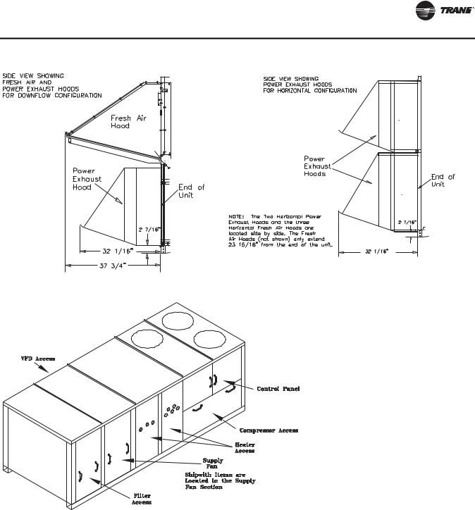
•Check for material shortages. Figure 11, p. 19 illustrates where “ship with” items are placed inside the unit.
If the job site inspection reveals damage or material shortages, file a claim with the carrier immediately. Specify the type and extent of the damage on the “bill of lading” before signing. Do not install a damaged unit without the Appropriate Trane sales representative's approval!
•Visually check the internal components for shipping damage as soon as possible after delivery and before it is stored. Do not walk on the sheet metal base pans.
 WARNING
No Step Surface!
Do not walk on the sheet metal drain pan. Walking on the drain pan could cause the supporting metal to collapse, resulting in the operator/technician to fall. Failure to follow this recommendation could result in death or serious injury.
Bridging between the unit's main supports may consist of multiple 2 by 12 boards or sheet metal grating.
•If concealed damage is discovered, notify the carrier's terminal office immediately by phone and by mail. Concealed damage must be reported within 15 days.
•Request an immediate joint inspection of the damage by the carrier and the consignee. Do not remove the damaged material from the receiving location. Take photos of the damage, if possible. The owner must provide reasonable evidence that the damage did not occur after delivery.
Storage
Take precautions to prevent condensate formation inside the unit electrical components and motors when:
a.The unit is stored before it is installed; or,
b.The unit is set on the roof curb and temporary auxiliary heat is provided in the building.
Isolate all side panel service entrances and base pan openings (e.g., conduit holes, S/A and R/A openings, and flue openings) to minimize ambient air from entering the unit until it is ready for startup.
Do not use the unit heater as temporary heat without completing the startup procedures detailed under “Startup,” p. 40.
Trane will not assume responsibility for equipment damage resulting from accumulation of condensate on the unit electrical components.
RT-SVX34H-EN |
13 |
Unit Dimensions and Weights
Recommended Clearances
Adequate clearance around and above each Voyager Commercial unit is required to ensure proper operation and to allow sufficient access for servicing.
If the unit installation is higher than the typical curb elevation, a field constructed catwalk around the unit is recommended to provide safe, easy access for maintenance and servicing. Table 1, p. 20 lists the recommended clearances for single and multiple unit installation. These clearances are necessary to assure adequate serviceability, cataloged capacities, and peak operating efficiency.
If the clearances available on the job site appear to be inadequate, review them with your Trane sales representative.
Roof Curb and Ductwork
The curbs for the 27.5 to 50 Ton commercial rooftop units enclose the entire unit base area. They are referred to as “full perimeter” type curbs.
Step-by-step instructions for the curb assembly and installation with curb dimensions and curb configuration for “A”, “B”, and “C” cabinets ship with each Trane accessory roof curb kit. (See the latest edition of the curb installation guide) Follow the instructions carefully to assure proper fit when the unit is set into place.
The S/A and R/A ductwork adjoining the roof curb must be fabricated and installed by the installing contractor before the unit is set into place. Trane curbs include flanges around the openings to accommodate duct attachment.
Ductwork installation recommendations are included in the instruction booklet that ships with each Trane accessory roof curb kit.
Note: For sound consideration, cut only the holes in the roof deck for the supply and return duct penetration. Do Not remove the roof decking from the inside perimeter of the curb.
If a Trane curb accessory kit is not used:
a.The ductwork can be attached directly to the S/A and R/A openings. Be sure to use a flexible duct connector at the unit.
b.For “built-up” curbs supplied by others, gaskets must be installed around the curb perimeter flange, Supply Air opening, and Return Air openings.
c.Insulation must be installed on the bottom of the condenser section of the unit.
Horizontal Ductwork
When attaching the ductwork to a horizontal supply or horizontal return unit, provide a water tight flexible connector at the unit to prevent noise transmission from
the unit into the ductwork. Refer to figures beginning on page 14 for the S/A and R/A opening dimensions.
All outdoor ductwork between the unit and the structure should be weather proofed after installation is completed.
If optional power exhaust is selected, an access door must be field-installed on the horizontal return ductwork to provide access to exhaust fan motors.
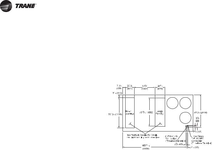
Figure 1. 60 Hz 27½-35, 50 Hz 23-29 Tons (TCD, TED, YCD low heat)
14 |
RT-SVX34H-EN |
Unit Dimensions and Weights
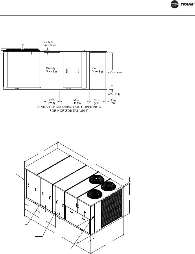
Figure 2. Rear view showing duct openings for horizontal supply and return, 60 Hz 27½-35, 50 Hz 23-29 Tons (TCH, TEH, YCH low heat)
3 1/4 |
1 1/4 |
(81) |
(32) |
Notes: |
|
• For combination of horizontal and downflow openings |
|
• On horizontal units, the VFD is located between the |
(digit 3 = F or R) see Figure 1, p. 14 for appropriate |
||
downflow/upflow dimensions and Figure 2, p. 15 for |
|||
supply and return ductwork, which makes access |
|||
appropriate horizontal dimensions. |
|||
limited. |
|
||
|
|
||
Figure 3. |
60 Hz 27½-35, 50 Hz 23-29 Tons (TC, TE, YC low heat) |
||
|
|
NOTES: |
|
|
|
1. SEE DETAIL HOOD DRAWING FOR HORIZONTAL / |
|
|
|
DOWNFLOW UNITS FOR ADDITIONAL DIMENSION |
|
|
|
AND LOCATION. |
|
|
90 3/8" |
|
|
|
2295.5mm |
|
|
|
180 5/16" |
|
|
|
4579.9mm |
|
|
SEE NOTE 2 |
|
|
|
|
|
3.25 [82.55mm] TO TOP OF FAN GRILLE |
|
70 7/16" 1789.1mm
42" |
|
|
1066.8mm |
|
|
|
5 3/8" |
|
|
136.5mm |
|
|
83 13/16" |
|
|
2128.8mm |
|
1 1/4" [31.7mm] |
7 9/16" |
|
FEMALE PVC PIPE |
192.1mm |
|
|
|
|
|
|
31.39" |
3/4" [19.0mm] NPT |
179 3/4" |
797.3mm |
GAS INLET |
4565.65mm |
|
6.91" |
90 1/16" |
175.6mm |
2287.5mm |
CUSTOMER
CONNECTION POINT
Note: Dimensions in ( ) are mm, 1”= 25.4 mm.
RT-SVX34H-EN |
15 |

Unit Dimensions and Weights
Figure 4. 60 Hz 27½-35, 50 Hz 23-29 Tons (YD high heat)
191 


Figure 5. Duct openings, 60 Hz 27½-35, 50 Hz 23-29 Tons (YH high heat)
3 1/4 |
1 1/4 |
(81) |
(32) |
Notes:
•On horizontal units, the VFD is located between the supply and return ductwork, which makes access limited.
•For combination of horizontal and downflow openings (digit 3 = F or R) see Figure 4, p. 16 for appropriate downflow/upflow dimensions and Figure 5, p. 16 for appropriate horizontal dimensions.
16 |
RT-SVX34H-EN |
Unit Dimensions and Weights
Figure 6. 60 Hz 27½-35, 50 Hz 23-29 Tons (YC high heat)
90 5/8" 2301.8mm
208 1/16" 5284.7mm
SEE NOTE 2
42" |
|
|
1066.8mm |
|
|
5 3/8" |
|
|
136.5m |
|
|
83 13/16" |
|
|
2128.8mm |
|
|
1 1/4" [31.7mm] |
|
|
PVC PIPE FEMALE |
7 9/16" |
|
|
192.1m |
|
1" [25.4MM] NPT |
207 1/2" |
|
GAS INLET |
|
|
|
5270.5mm |
|
|
|
31.39" |
|
|
797.3mm |
|
CUSTOMER |
|
|
CONNECTION POINT |
6.89" |
175mm
NOTES:
1.SEE ROOFCURB DRAWING FOR DETAILS ON FIELD DUCT FITUP AND CONNECTIONS
2.SEE DETAIL HOOD DRAWING FOR HORIZONTAL / DOWNFLOW UNITS FOR ADDITIONAL DIMENSION AND LOCATION.
3.25 [82.55mm] TO TOP OF FAN GRILLE
70 7/16" 1789.1mm
90 1/16" 2287.5mm
Note: Dimensions in ( ) are mm, 1”= 25.4 mm.
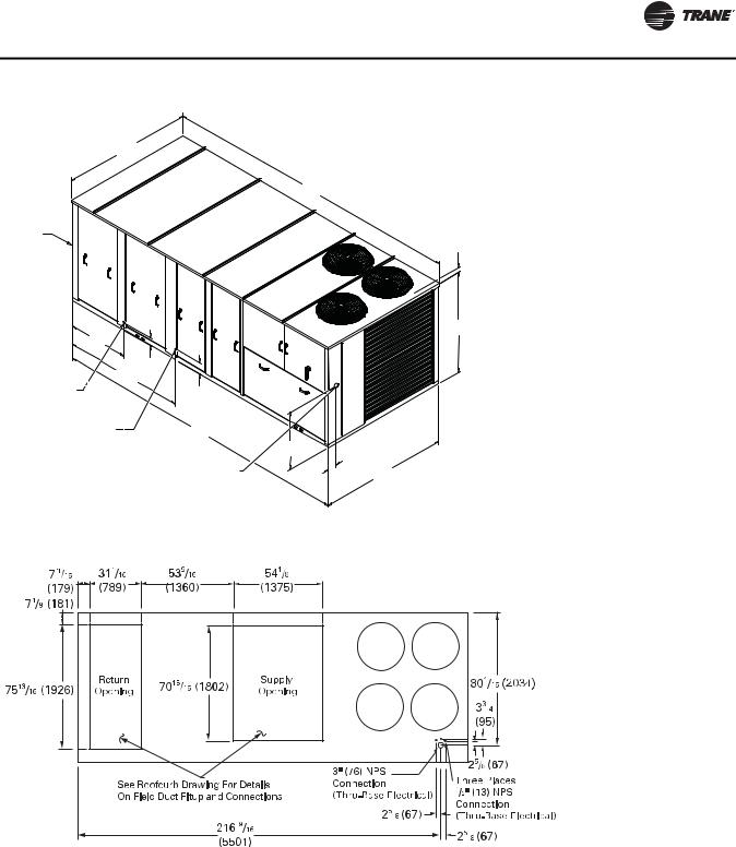
Figure 7. 60 Hz 40-50, 50 Hz 33-42 Tons (TD, TD, YD low and high heat)
RT-SVX34H-EN |
17 |
Unit Dimensions and Weights
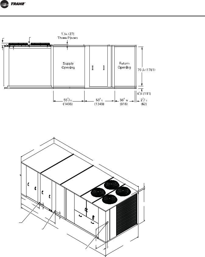
Figure 8. Duct openings, 60 Hz 40-50, 50 Hz 33-42 Tons (TH, TH, YH low and high heat)
3 1/4 |
1 1/4 |
(81) |
(32) |
Notes: |
|
• For combination of horizontal and downflow openings |
|
• On horizontal units, the VFD is located between the |
(digit 3 = F or R) see Figure 7, p. 17 for appropriate |
||
downflow/upflow dimensions and Figure 8, p. 18 for |
|||
supply and return ductwork, which makes access |
|||
appropriate horizontal dimensions. |
|||
limited. |
|
||
|
|
||
Figure 9. |
60 Hz 40-50, 50 Hz 33-42 Tons (TC, TE, YC low and high heat) |
||
90 5/8" 2301.8mm
232 3/4" 5911.8mm
SEE NOTE 2 
49 9/16" |
|
1258.8mm |
|
5 5/16" |
|
136.5m |
|
93 3/8" |
|
2371.7mm |
|
1 1/4" [31.7mm] |
7 9/16" |
PVC PIPE FEMALE |
192.1m |
|
|
1" [25.4MM] NPT |
232 3/8" |
HIGH HEAT GAS INLET |
5902.3mm |
3/4" [19MM] NPT
LOW HEAT GAS INLET
32.84" 834.2mm

CUSTOMER
CONNECTION POINT
NOTES:
1.SEE ROOFCURB DRAWING FOR DETAILS ON FIELD DUCT FITUP AND CONNECTIONS
2.SEE DETAIL HOOD DRAWING FOR HORIZONTAL / DOWNFLOW UNITS FOR ADDITIONAL DIMENSION AND LOCATION.
3.25 [82.55mm] TO TOP OF FAN GRILLE
77"
1955.8mm
90 1/16" 4.66" 2287.5mm
 118.4mm
Note: Dimensions in ( ) are mm, 1”= 25.4 mm.
18 |
RT-SVX34H-EN |
Unit Dimensions and Weights
Figure 10. Fresh air and power exhaust dimensions for TC*, TE*, and YC* units
Figure 11. Location of “Ship With” items for TC*, TE*, and YC* units
RT-SVX34H-EN |
19 |
Unit Dimensions and Weights
Unit Rigging and Placement
 WARNING
Heavy Objects!
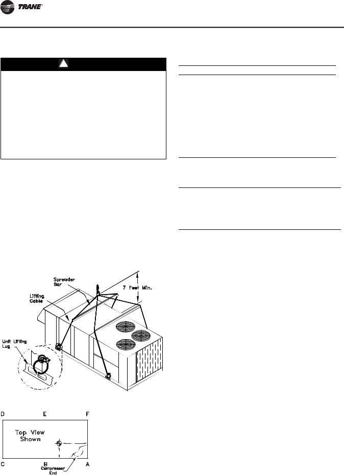
Ensure that all the lifting equipment used is properly rated for the weight of the unit being lifted. Each of the cables (chains or slings), hooks, and shackles used to lift the unit must be capable of supporting the entire weight of the unit. Lifting cables (chains or slings) may not be of the same length. Adjust as necessary for even unit lift. Other lifting arrangements could cause equipment or property damage. Failure to follow instructions above or properly lift unit could result in unit dropping and possibly crushing operator/ technician which could result in death or serious injury.
Use spreader bars as shown in the diagram. Refer to the Installation manual or nameplate for unit weight. Refer to the Installation instructions located inside the control panel for further rigging information.
1.Verify that the roof curb has the proper gaskets installed and is level and square to assure an adequate curb-to-unit seal.
The units must be as level as possible in order to assure proper condensate flow out of the unit. The maximum side-to-side and end-to-end slope allowable in any application is listed in Table 2, p. 20.
Figure 12. Unit rigging
Figure 13. Center of gravity
|
Y |
Z (see note 2) |
X |
|
Table 1. Minimum operating clearances installation (horizontal, downflow, and mixed airflow configurations)
Recommended Clearances
Condenser
Coil(a)
|
Economizer/ |
Orientation |
Service Side |
|
Single Unit Exhaust End |
End/Side |
Access |
||
|
|
|
|
|
TC*, TE*, YC* |
6 Feet |
8 Feet |
4 Feet |
|
27.5 to 50 Tons |
||||
|
|
|
||
|
|
|
||
|
Distance Between Units |
|
||
|
|
|
|
|
|
Economizer/ |
|
Service Side |
|
Multiple Unit Exhaust End |
End/Side |
Access |
||
|
|
|
|
|
TC*, TE*, YC* |
12 Feet |
16 Feet |
8 Feet |
|
27.5 to 50 Tons |
||||
|
|
|
||
(a) Condenser coil is located at the end and side of the unit.
Table 2. Maximum slope
|
End to End |
Side to Side |
Cabinet |
(inches) |
(inches) |
|
|
|
“A” (27.5 - 35 Ton Low Heat) |
3 1/2 |
1 5/8 |
|
|
|
“B” (27.5 - 35 Ton High Heat) |
4 |
1 5/8 |
|
|
|
“C” (All 40 and 50 Ton Units) |
4 1/2 |
1 5/8 |
Note: Do not exceed these allowances. Correct the improper slope by building up the curb base. The material used to raise the base must be adequate to support both the curb and the unit weight.
Table 3. Center of gravity
|
|
|
Center-of-Gravity (inches) |
|
|||||
|
|
|
|
|
|
||||
|
YC Low Heat |
YC High Heat |
|
TC/TE |
|
||||
|
Dimension |
Dimension |
Dimension |
||||||
|
|
|
|
|
|
|
|
|
|
Unit Model |
X |
Y |
Z |
X |
Y |
Z |
X |
Y |
Z |
|
|
|
|
|
|
|
|
|
|
***330/275* |
41 |
76 |
33 |
41 |
84 |
33 |
42 |
76 |
33 |
|
|
|
|
|
|
|
|
|
|
***360/305* |
43 |
77 |
33 |
43 |
85 |
33 |
44 |
77 |
33 |
|
|
|
|
|
|
|
|
|
|
***420/350* |
42 |
78 |
33 |
42 |
86 |
33 |
43 |
78 |
33 |
|
|
|
|
|
|
|
|
|
|
***480/400* |
42 |
111 |
35 |
42 |
111 |
35 |
42 |
111 |
35 |
|
|
|
|
|
|
|
|
|
|
***600/500* |
43 |
108 |
35 |
43 |
108 |
35 |
43 |
108 |
35 |
|
|
|
|
|
|
|
|
|
|
Note: Center-of-gravity dimensions are approximate, and are based on the unit equipped with: standard efficiency coils, standard efficiency motors, economizer, and throwaway filters.
Note: Z dimension is upward from the base of the unit. Example:
Locating the center-of-gravity for a YC-360 MBH High Heat unit with 100% exhaust.
X = 43 inches inward from the control panel side Y = 85 inches inward from the compressor end Z = 33 inches upward from the base
20 |
RT-SVX34H-EN |
Unit Dimensions and Weights
Table 4. Approximate units operating weights — lbs./kg1
|
|
Basic Unit Weights1 |
|
|
Unit Models |
YC |
YC |
|
|
(60Hz/50Hz) |
Low Heat |
High Heat |
TC |
TE |
|
|
|
|
|
330/275 |
3720 / 1687 |
4150 / 1882 |
3590 / 1628 |
3610 / 1637.5 |
360/305 |
3795 / 1721 |
4225 / 1916 |
3665 / 1662 |
3685 / 1671.5 |
420/350 |
3876 / 1758 |
4306 / 1953 |
3746 / 1699 |
3766 / 1708 |
480/400 |
4825 / 2189 |
4950 / 2245 |
4565 / 2071 |
4600 / 2086.5 |
600/500 |
5077 / 2303 |
5202 / 2360 |
4827 / 2189.5 |
4852 / 2201 |
|
|
|
|
|
1. Basic unit weight includes minimum horsepower supply fan motor.
Table 5. Point loading average weight1,2 — lbs./kg
Unit Models |
|
|
|
|
|
|
(60Hz/50Hz) |
A |
B |
C |
D |
E |
F |
|
|
|
|
|
|
|
330/275 |
852 / 386 |
695 / 315 |
754 / 342 |
740 / 335 |
602 / 273 |
504 / 228 |
360/305 |
878 / 398 |
681 / 309 |
750 / 340 |
713 / 323 |
577 / 262 |
622 / 282 |
420/350 |
841 / 381 |
842 / 382 |
669 / 303 |
735 / 333 |
582 / 264 |
634 / 287 |
480/400 |
835 / 378 |
869 / 394 |
950 / 431 |
748 / 339 |
769 / 349 |
776 / 352 |
600/500 |
882 / 400 |
931 / 422 |
954 / 433 |
740 / 336 |
844 / 382 |
847 / 384 |
|
|
|
|
|
|
|
Notes:
1.Point loading is identified with corner A being the corner with the compressors. As you move clockwise around the unit as viewed from the top, mid-point B, corner C, corner D, mid-point E and corner F.
2.Point load calculations provided are based on the unit weight for YC high heat gas models.
D E F
TOP VIEW
OF UNIT
COMPRS
C B A
RT-SVX34H-EN |
21 |

Unit Dimensions and Weights
Table 6. Approximate operating weights— optional components — lbs./kg
|
|
|
|
|
Var. Freq. Drives |
|
|
|
Factory |
|
|
|
|
|
|
|
|
(VFD’s) |
|
Thru- |
Non- |
GFI |
|
|
|
|
|
|
0-25% |
|
|
|
|
the |
Fused |
with |
|
|
|
|
|
|
W/O |
With |
|
Roof Curb |
|||||
Unit Model |
Baro. |
Power |
Man |
|
Serv |
base |
Discon. |
Discon. |
||||
|
|
|
|
|
||||||||
|
|
|
|
|
||||||||
(60Hz/50Hz) |
Relief |
Exhaust |
Damper |
Econ. |
Bypass |
Valves |
Elec. |
Switch |
Switch |
Lo |
Hi |
|
|
|
|
|
|
|
|
|
|
|
|
|
|
**(D,F)330/275 |
110/50 |
165/74 |
50/23 |
260/117 |
85/39 |
115/52 |
18/8 |
6/3 |
30/14 |
85/38 |
310/141 |
330/150 |
**(H,R)330/275 |
145/65 |
200/90 |
50/23 |
285/128 |
85/39 |
115/52 |
18/8 |
6/3 |
30/14 |
85/38 |
310/141 |
330/150 |
**(D,F)360/305 |
110/50 |
165/74 |
50/23 |
260/117 |
85/39 |
115/52 |
18/8 |
6/3 |
30/14 |
85/38 |
310/141 |
330/150 |
**(H,R)360/305 |
145/65 |
200/90 |
50/23 |
285/128 |
85/39 |
115/52 |
18/8 |
6/3 |
30/14 |
85/38 |
310/141 |
330/150 |
**(D,F)420/350 |
110/50 |
165/74 |
50/23 |
260/117 |
85/39 |
115/52 |
18/8 |
6/3 |
30/14 |
85/38 |
310/141 |
330/150 |
**(H,R)420/350 |
145/65 |
200/90 |
50/23 |
285/128 |
85/39 |
115/52 |
18/8 |
6/3 |
30/14 |
85/38 |
310/141 |
330/150 |
**(D,F)480/400 |
110/50 |
165/74 |
50/23 |
290/131 |
115/52 |
150/68 |
18/8 |
6/3 |
30/14 |
85/38 |
365/169 |
365/169 |
**(H,R)480/400 |
145/65 |
200/90 |
50/23 |
300/135 |
115/52 |
150/68 |
18/8 |
6/3 |
30/14 |
85/38 |
365/169 |
365/169 |
**(D,F)600/500 |
110/50 |
165/74 |
50/23 |
290/131 |
115/52 |
150/68 |
18/8 |
6/3 |
30/14 |
85/38 |
365/169 |
365/169 |
**(H,R)600/500 |
145/65 |
200/90 |
50/23 |
300/135 |
115/52 |
150/68 |
18/8 |
6/3 |
30/14 |
85/38 |
365/169 |
365/169 |
|
|
|
|
|
|
|
|
|
|
|
|
|
|
|
|
|
Ultra |
|
|
|
|
|
|
|
|
|
|
Tool-Less |
Ultra |
Low |
Ultra Low |
|
|
|
|
|
|
|
|
|
Condenser |
Low |
Leak |
Leak |
High |
|
|
|
|
|
|
Unit Model |
HGRH |
Hail |
Leak |
50% |
100% |
Efficiency |
|
|
|
|
|
|
(60Hz/50Hz) |
Coil |
Guards |
Econ |
Exhaust |
Exhaust |
(eStage) |
|
|
|
|
|
|
|
|
|
|
|
|
|
|
|
|
|
|
|
**(D,F)330/275 |
107/49 |
105/48 |
112/51 |
34 / 15 |
74 / 34 |
326/148 |
|
|
|
|
|
|
**(H,R)330/275 |
107/49 |
105/48 |
78/35 |
34 / 15 |
77 / 35 |
326/148 |
|
|
|
|
|
|
**(D,F)360/305 |
107/49 |
105/48 |
112/51 |
34 / 15 |
74 / 34 |
255/116 |
|
|
|
|
|
|
**(H,R)360/305 |
107/49 |
105/48 |
78 /35 |
34 / 15 |
77 / 35 |
255/116 |
|
|
|
|
|
|
**(D,F)420/350 |
107/49 |
105/48 |
112/51 |
34 / 15 |
74 / 34 |
173/78 |
|
|
|
|
|
|
**(H,R)420/350 |
107/49 |
105/48 |
78/35 |
34 / 15 |
77 / 35 |
173/78 |
|
|
|
|
|
|
**(D,F)480/400 |
112/51 |
130/59 |
114/52 |
34 / 15 |
74 / 34 |
241/109 |
|
|
|
|
|
|
**(H,R)480/400 |
112/51 |
130/59 |
100/45 |
34 / 15 |
84 / 38 |
241/109 |
|
|
|
|
|
|
**(D,F)600/500 |
112/51 |
130/59 |
114/52 |
34 / 15 |
74 / 34 |
-25/-11 |
|
|
|
|
|
|
**(H,R)600/500 |
112/51 |
130/59 |
100/45 |
34 / 15 |
84 / 38 |
-25/-11 |
|
|
|
|
|
|
|
|
|
|
|
|
|
|
|
|
|
|
|
Note: Basic unit weight includes minimum horsepower supply fan motor.
22 |
RT-SVX34H-EN |
Installation General Requirements
Condensate Drain Connection
Each commercial rooftop unit is equipped with one (1) 1- 1/4 inch Female PVC condensate drain connection.
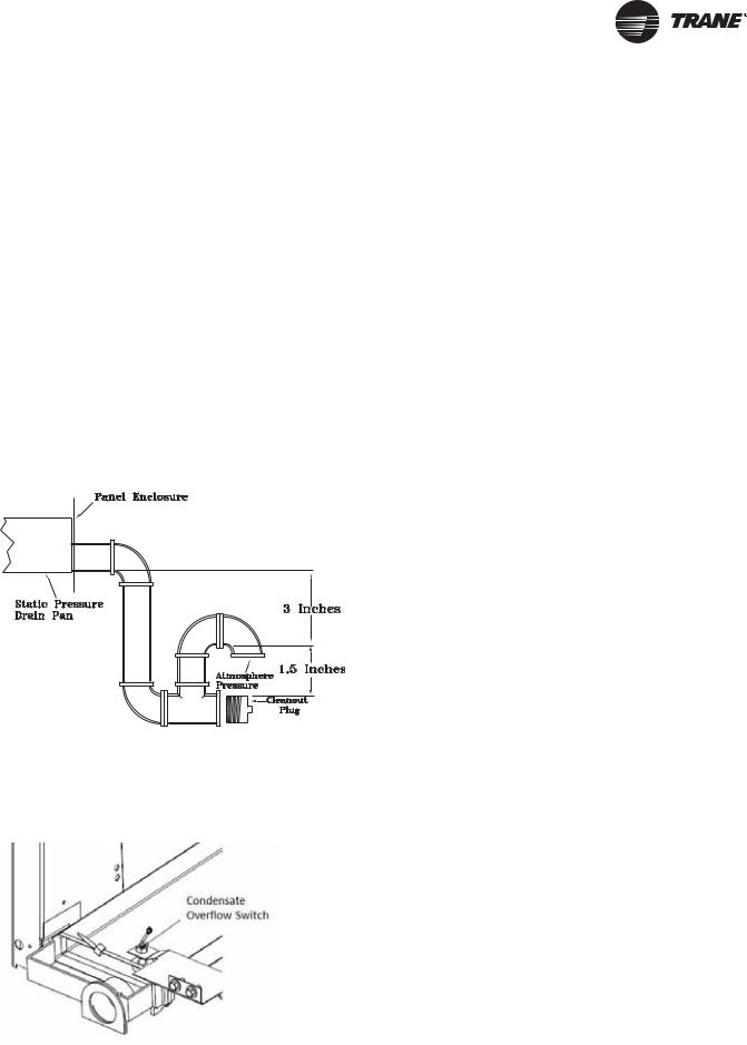
Refer to Figure 11, p. 19 for the location of the connector. A condensate trap must be installed due to the drain connection being on the “negative pressure” side of the fan. Install a P-Trap at the unit using the guidelines in Figure 14, p. 23.
Pitch the drain line at least 1/2 inch for every 10 feet of horizontal run to assure proper condensate flow.
Ensure that all condensate drain line installations comply with applicable building and waste disposal codes.
Notes:
•For units with optional Condensate Overflow Switch (COF), the switch will not work properly if unit is not level or slightly sloped toward switch.
•To ensure proper condensate flow during operation the unit and the curb must be level.
Figure 14. Condensate trap installation
Condensate Overflow Switch
This switch protects building from condensate overflow damage. It is factory-installed and tested.
Figure 15. Condensate overflow switch location
O/A Sensor & Tubing Installation
An Outside Air Pressure Sensor is shipped with all units designed to operate on traditional variable air volume applications (non-SZ VAV) and units with Statitrac™.
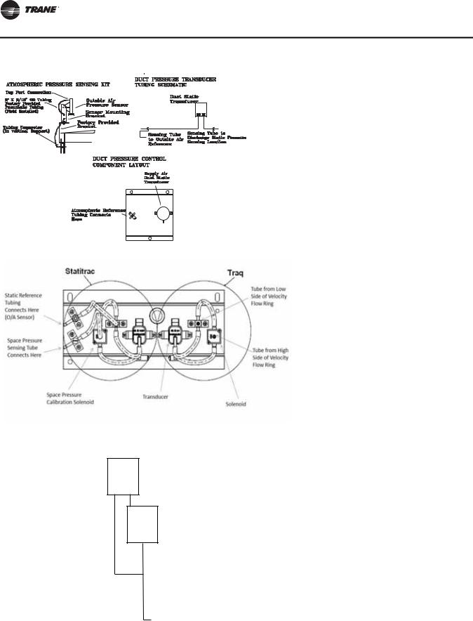
A duct pressure transducer and the outside air sensor is used to control the discharge duct static pressure to within a customer-specified controlband. Refer to the illustration in Figure 16, p. 24 and the following steps to install the sensor and the pneumatic tubing.
1.Remove the O/A pressure sensor kit located inside the fan section. The kit contains the following items;
•an O/A static pressure sensor
•a sensor mounting bracket
•50’ of 3/16” O.D. pneumatic tubing
•mounting hardware
2.Using two #10-32 x 1-3/4” screws provided, install the sensor's mounting bracket to the factory provided bracket (near the fan section).
3.Using the #10-32 x 1/2” screws provided, install the O/ A static pressure sensor vertically to the sensor bracket.
4.Remove the dust cap from the tubing connector located below the sensor in the vertical support.
5.Attach one end of the 50' x 3/16” O.D. factory provided pneumatic tubing to the sensor's top port, and the other end of the tubing to the connector in the vertical support. Discard any excess tubing.
Units with Statitrac™
1.Open the filter access door, and locate the Statitrac Transducer Assembly illustrated in Figure 17, p. 24. There are two tube connectors mounted on the left of the solenoid and transducers. Connect one end of the field provided 1/4” (length 50-100 ft.) or 3/8” (length greater than 100 ft.) O.D. pneumatic tubing for the space pressurization control to the fitting indicated in the illustration.
2.Route the opposite end of the tubing to a suitable location inside the building. This location should be the largest open area that will not be affected by sudden static pressure changes.
RT-SVX34H-EN |
23 |
Installation General Requirements
Figure 16. Pressure tubing
Figure 17. Transducer assembly
Airflow
Transducer
Sensing Tube
LO HI to Traq HI Side
Pressure Port
C NO
NC
Sensing Tube to Traq LO Side Pressure Port
Note: Statitrac and Traq transducer assembly shown.
24 |
RT-SVX34H-EN |
Installation Electrical
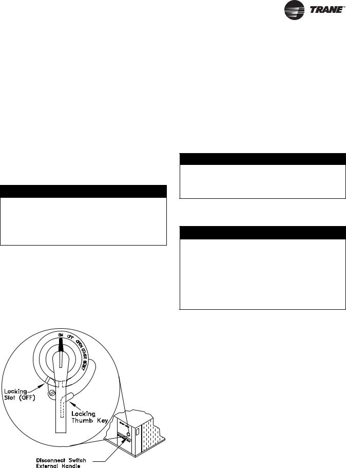
Disconnect Switch External
Handle (Factory Mounted Option)
Units ordered with the factory mounted disconnect switch come equipped with an externally mounted handle. This allows the operator to disconnect power from the unit without having to open the control panel door. The handle location and its three positions are shown below;
ON - Indicates that the disconnect switch is closed, allowing the main power supply to be applied at the unit.
OFF - Indicates that the disconnect switch is open, interrupting the main power supply at the unit.
OPEN COVER/RESET - Turning the handle to this position releases the handle from the disconnect switch, allowing the control panel door to be opened.
 WARNING
Hazardous Voltage!
Disconnect all electric power, including remote disconnects before servicing. Follow proper lockout/ tagout procedures to ensure the power can not be inadvertently energized. Failure to disconnect power before servicing could result in death or serious injury.
Once the door has been opened, it can be closed with the handle in any one of the three positions outlined above, provided it matches the disconnect switch position. The handle can be locked in the “OFF” position. While holding the handle in the “OFF” position, push the spring loaded thumb key, attached to the handle, into the base slot. Place the lock shackle between the handle and the thumb key. This will prevent it from springing out of position.
Figure 18. Disconnect switch
An overall layout of the field required power wiring is illustrated in Figure 19, p. 26. To insure that the unit supply power wiring is properly sized and installed, follow the guidelines outlined below.
Note: All field installed wiring must conform to NEC guidelines as well as State and Local codes.
Verify that the power supply available is compatible with the unit's name plate ratings for all components. The available power supply must be within 10% of the rated voltage stamped on the nameplate. Use only copper conductors to connect the 3-phase power supply to the unit.
NOTICE:
Use Copper Conductors Only!
Unit terminals are not designed to accept other types of conductors. Failure to use copper conductors could result in equipment damage.
Main Power Wiring
 WARNING
Proper Field Wiring and Grounding
Required!
All field wiring MUST be performed by qualified personnel. Improperly installed and grounded field wiring poses FIRE and ELECTROCUTION hazards. To avoid these hazards, you MUST follow requirements for field wiring installation and grounding as described in NEC and your local/state electrical codes. Failure to follow code could result in death or serious injury.
1.Table 7, p. 27 to Table 12, p. 29 list the electrical service sizing data. The electrical service must be protected from over current and short circuit conditions in accordance with NEC requirements. Protection devices must be sized according to the electrical data on the nameplate. Refer to “Electrical Wire Sizing and Protection Device Equations” on page 29 for determining:
a.The appropriate electrical service wire size based on “Minimum Circuit Ampacity” (MCA),
b.The “Maximum Over current Protection” (MOP) device.
c.The “Recommended Dual Element fuse size” (RDE).
2.If the unit is not equipped with an optional factory installed Nonfused disconnect switch, a field supplied disconnect switch must be installed at or near the unit in accordance with the National Electrical Code (NEC latest edition). Refer to DSS calculations “Electrical Wire Sizing and Protection Device Equations” on page 29 for determining correct size.
RT-SVX34H-EN |
25 |

Installation Electrical
Location for the electrical service entrance is shown in the unit dimensional drawings beginning with Figure 1, p. 14. Complete the unit's power wiring connections onto either the main terminal block HTB1, or the factory mounted nonfused disconnect switch inside the unit control panel.
Note: When the factory installed through-the-base option is not used, the installing contractor is required to seal any holes made in the base of the unit to prevent water from leaking into the building.
3.Provide proper grounding for the unit in accordance with local and national codes.
Figure 19. Typical field power wiring
Through-the-Base Electrical (Optional
Accessory)
Liquid-tight conduit couplings are secured to the base of the unit for both power and control wiring. Liquid-tight conduit must be field installed between the couplings and the unit control box to prevent water leaks into the building.
Note: If the unit is set on the roof curb and temporary auxiliary heat is provided in the building, it is recommended that the electrical and control wiring conduit opening in the control box be temporarily sealed to provide a vapor barrier.
26 |
RT-SVX34H-EN |

Installation Electrical
Table 7. |
27½-50 ton electrical service sizing data—60Hz1 |
|
|
|
|
|
|
|
|
|
|
|
|
||||||
|
|
|
|
|
|
|
|
|
Fan Motors |
|
|
|
|
|
|
|
|
||
|
|
|
|
|
|
|
|
|
|
|
|
|
|
|
|
|
|||
|
|
|
Compressor - Std |
Compressor - High |
|
|
|
|
|
|
|
|
|
|
|||||
|
|
|
|
Efficiency |
Efficiency, eStage |
Supply |
Condenser |
|
|
Exhaust |
|
||||||||
|
|
|
|
|
|
|
|
|
|
|
|
|
|
|
|
|
|
|
|
|
Electrical |
Allowable |
|
|
|
|
|
|
|
|
|
|
|
|
50 |
|
100 |
|
|
|
|
|
|
|
|
|
|
|
|
|
|
|
% |
|
% |
|
|
||
|
Characteri |
Voltage |
No/ |
|
RLA |
LRA |
No/ |
RLA |
LRA |
|
|
|
|
FLA |
|
|
FLA |
||
|
|
|
|
|
|
|
|
|
|
||||||||||
Model |
stics |
Range |
Ton |
|
(Ea.) |
(Ea.) |
Ton |
(Ea.) |
(Ea.) |
HP |
FLA |
No |
HP |
(Ea.) |
|
No. |
HP |
(Ea.) |
|
|
|
|
|
|
|
|
|
|
|
|
|
|
|
|
|
|
|
|
|
|
208/60/3 |
187-229 |
1/12, |
|
44.0/ |
304/ |
1/6, |
28.0, |
203, |
7.5 |
22.2 |
3 |
1.1 |
7.0 |
1 |
|
2 |
1.0 |
4.1 |
|
1/13 |
|
50.5 |
315 |
2/9 |
37.1 |
267 |
10.0 |
29.5 |
|
|||||||||
|
|
|
|
|
|
|
|
|
|
|
|
||||||||
|
|
|
|
|
|
|
|
|
|
|
|
|
|
|
|
|
|
|
|
|
230/60/3 |
207-253 |
1/12, |
|
44.0/ |
304/ |
1/6, |
28.0, |
203, |
7.5 |
18.8 |
3 |
1.1 |
7.0 |
1 |
|
2 |
1.0 |
4.1 |
TC/TE/ |
1/13 |
|
50.5 |
315 |
2/9 |
37.1 |
267 |
10.0 |
25.2 |
|
|||||||||
|
|
|
|
|
|
|
|
|
|
|
|||||||||
YC*330 |
460/60/3 |
414-506 |
1/12, |
|
21.0/ |
147/ |
1/6, |
14.1, |
98, 142 |
7.5 |
9.4 |
3 |
1.1 |
3.5 |
1 |
|
2 |
1.0 |
1.8 |
|
|
|
|||||||||||||||||
|
|
|
1/13 |
|
23.0 |
158 |
2/9 |
16.8 |
|
10.0 |
12.6 |
|
|
|
|
|
|
|
|
|
575/60/3 |
517-633 |
1/12, |
|
17.5/ |
122/ |
1/6, |
12.2, |
84, 103 |
7.5 |
7.8 |
3 |
1.1 |
2.8 |
1 |
|
2 |
1.0 |
1.4 |
|
1/13 |
|
19.0 |
136 |
2/9 |
14.7 |
10.0 |
10.1 |
|
||||||||||
|
|
|
|
|
|
|
|
|
|
|
|
|
|
|
|
|
|
|
|
|
208/60/3 |
187-229 |
2/13 |
|
50.5 |
315/ |
1/6, |
28.0, |
203, |
7.5 |
22.2 |
3 |
1.1 |
7.0 |
1 |
|
2 |
1.0 |
4.1 |
|
|
315 |
2/10 |
40.9 |
267 |
10.0 |
29.5 |
|
|||||||||||
|
|
|
|
|
|
|
|
|
|
|
|
|
|
||||||
|
|
|
|
|
|
|
|
|
|
|
|
|
|
|
|
|
|
|
|
|
230/60/3 |
207-253 |
2/13 |
|
50.5 |
315/ |
1/6, |
28.0, |
203, |
7.5 |
18.8 |
3 |
1.1 |
7.0 |
1 |
|
2 |
1.0 |
4.1 |
TC/TE/ |
|
315 |
2/10 |
40.9 |
267 |
10.0 |
25.2 |
|
|||||||||||
|
|
|
|
|
|
|
|
|
|
|
|
|
|||||||
YC*360 |
460/60/3 |
414-506 |
2/13 |
|
23.0 |
158/ |
1/6, |
14.1, |
98, 142 |
7.5 |
9.4 |
3 |
1.1 |
3.5 |
1 |
|
2 |
1.0 |
1.8 |
|
|
158 |
2/10 |
18.6 |
10.0 |
12.6 |
|
||||||||||||
|
|
|
|
|
|
|
|
|
|
|
|
|
|
|
|
|
|
|
|
|
575/60/3 |
517-633 |
2/13 |
|
19.0 |
136/ |
1/6, |
12.2, |
84, 103 |
7.5 |
7.8 |
3 |
1.1 |
2.8 |
1 |
|
2 |
1.0 |
1.4 |
|
|
136 |
2/10 |
15.4 |
10.0 |
10.1 |
|
||||||||||||
|
|
|
|
|
|
|
|
|
|
|
|
|
|
|
|
|
|
|
|
|
|
|
1/13, |
|
50.5/ |
315/ |
1/6, |
28.0, |
203, |
7.5 |
22.2 |
|
|
|
|
|
|
|
|
|
208/60/3 |
187-229 |
|
10.0 |
29.5 |
3 |
1.1 |
7.0 |
1 |
|
2 |
1.0 |
4.1 |
||||||
|
1/15 |
|
56.0 |
351 |
2/11 |
44.9 |
304 |
|
|||||||||||
|
|
|
|
15.0 |
40.7 |
|
|
|
|
|
|
|
|
||||||
|
|
|
|
|
|
|
|
|
|
|
|
|
|
|
|
|
|
||
|
|
|
|
|
|
|
|
|
|
|
|
|
|
|
|
|
|
|
|
|
|
|
1/13, |
|
50.5/ |
315/ |
1/6, |
28.0, |
203, |
7.5 |
18.8 |
|
|
|
|
|
|
|
|
|
230/60/3 |
207-253 |
|
10.0 |
25.2 |
3 |
1.1 |
7.0 |
1 |
|
2 |
1.0 |
4.1 |
||||||
|
1/15 |
|
56.0 |
351 |
2/11 |
44.9 |
304 |
|
|||||||||||
TC/TE/ |
|
|
|
15.0 |
35.4 |
|
|
|
|
|
|
|
|
||||||
|
|
|
|
|
|
|
|
|
|
|
|
|
|
|
|
|
|||
YC*420 |
|
|
1/13, |
|
23.0/ |
158/ |
1/6, |
14.1, |
98, |
7.5 |
9.4 |
|
|
|
|
|
|
|
|
|
460/60/3 |
414-506 |
|
10.0 |
12.6 |
3 |
1.1 |
3.5 |
1 |
|
2 |
1.0 |
1.8 |
||||||
|
1/15 |
|
27.5 |
197 |
2/11 |
19.2 |
147 |
|
|||||||||||
|
|
|
|
15.0 |
17.7 |
|
|
|
|
|
|
|
|
||||||
|
|
|
|
|
|
|
|
|
|
|
|
|
|
|
|
|
|
||
|
|
|
|
|
|
|
|
|
|
|
|
|
|
|
|
|
|
|
|
|
|
|
1/13, |
|
19.0/ |
136/ |
1/6, |
12.2, |
84, |
7.5 |
7.8 |
|
|
|
|
|
|
|
|
|
575/60/3 |
517-633 |
|
10.0 |
10.1 |
3 |
1.1 |
2.8 |
1 |
|
2 |
1.0 |
1.4 |
||||||
|
1/15 |
|
23.0 |
146 |
2/11 |
16.6 |
122 |
|
|||||||||||
|
|
|
|
15.0 |
15.1 |
|
|
|
|
|
|
|
|
||||||
|
|
|
|
|
|
|
|
|
|
|
|
|
|
|
|
|
|
||
|
|
|
|
|
|
|
|
|
|
|
|
|
|
|
|
|
|
|
|
|
208/60/3 |
187-229 |
1/13, |
|
50.5/ |
315/ |
1/8, |
31.1, |
203, |
10.0 |
29.5 |
4 |
1.1 |
7.0 |
1 |
|
2 |
1.5 |
5.4 |
|
1/20 |
|
83.9 |
485 |
2/13 |
50.5 |
315 |
15.0 |
40.7 |
|
|||||||||
|
|
|
|
|
|
|
|
|
|
|
|
||||||||
|
|
|
|
|
|
|
|
|
|
|
|
|
|
|
|
|
|
|
|
|
230/60/3 |
207-253 |
1/13, |
|
50.5/ |
315/ |
1/8, |
31.1, |
203, |
10.0 |
25.2 |
4 |
1.1 |
7.0 |
1 |
|
2 |
1.5 |
5.4 |
TC/TE/ |
1/20 |
|
83.9 |
485 |
2/13 |
50.5 |
315 |
15.0 |
35.4 |
|
|||||||||
|
|
|
|
|
|
|
|
|
|
|
|||||||||
YC*480 |
460/60/3 |
414-506 |
1/13, |
|
23.0/ |
158/ |
1/8, |
14.1, |
98, |
10.0 |
12.6 |
4 |
1.1 |
3.5 |
1 |
|
2 |
1.5 |
2.7 |
|
1/20 |
|
34.0 |
215 |
2/13 |
23.0 |
158 |
15.0 |
17.7 |
|
|||||||||
|
|
|
|
|
|
|
|
|
|
|
|
||||||||
|
|
|
|
|
|
|
|
|
|
|
|
|
|
|
|
|
|
|
|
|
575/60/3 |
517-633 |
1/13, |
|
19.0/ |
136/ |
1/8, |
11.5, |
84, |
10.0 |
10.1 |
4 |
1.1 |
2.8 |
1 |
|
2 |
1.5 |
2.2 |
|
1/20 |
|
27.3 |
175 |
2/13 |
19.0 |
136 |
15.0 |
15.1 |
|
|||||||||
|
|
|
|
|
|
|
|
|
|
|
|
||||||||
|
|
|
|
|
|
|
|
|
|
|
|
|
|
|
|
|
|
|
|
|
|
|
2/13, |
|
50.5/ |
315/ |
1/10, |
40.9, |
267, |
10.0 |
29.5 |
|
|
|
|
|
|
|
|
|
208/60/3 |
187-229 |
|
15.0 |
40.7 |
4 |
1.1 |
7.0 |
1 |
|
2 |
1.5 |
5.4 |
||||||
|
1/15 |
|
56.0 |
351 |
2/15 |
56.0 |
345 |
|
|||||||||||
|
|
|
|
20.0 |
56.1 |
|
|
|
|
|
|
|
|
||||||
|
|
|
|
|
|
|
|
|
|
|
|
|
|
|
|
|
|
||
|
|
|
|
|
|
|
|
|
|
|
|
|
|
|
|
|
|
|
|
|
|
|
2/13, |
|
50.5/ |
315/ |
1/10, |
40.9, |
267, |
10.0 |
25.2 |
|
|
|
|
|
|
|
|
|
230/60/3 |
207-253 |
|
15.0 |
35.4 |
4 |
1.1 |
7.0 |
1 |
|
2 |
1.5 |
5.4 |
||||||
|
1/15 |
|
56.0 |
351 |
2/15 |
56.0 |
345 |
|
|||||||||||
TC/TE/ |
|
|
|
20.0 |
49.4 |
|
|
|
|
|
|
|
|
||||||
|
|
|
|
|
|
|
|
|
|
|
|
|
|
|
|
|
|||
YC*600 |
|
|
2/13, |
|
23.0/ |
158/ |
1/10, |
18.6, |
142, |
10.0 |
12.6 |
|
|
|
|
|
|
|
|
|
460/60/3 |
414-506 |
|
15.0 |
17.7 |
4 |
1.1 |
3.5 |
1 |
|
2 |
1.5 |
2.7 |
||||||
|
1/15 |
|
27.5 |
197 |
2/15 |
27.5 |
155 |
|
|||||||||||
|
|
|
|
20.0 |
24.7 |
|
|
|
|
|
|
|
|
||||||
|
|
|
|
|
|
|
|
|
|
|
|
|
|
|
|
|
|
||
|
|
|
|
|
|
|
|
|
|
|
|
|
|
|
|
|
|
|
|
|
|
|
2/13, |
|
19.0/ |
136/ |
1/10, |
15.4, |
103, |
10.0 |
10.1 |
|
|
|
|
|
|
|
|
|
575/60/3 |
517-633 |
|
15.0 |
15.1 |
4 |
1.1 |
2.8 |
1 |
|
2 |
1.5 |
2.2 |
||||||
|
1/15 |
|
23.0 |
146 |
2/15 |
23.0 |
126 |
|
|||||||||||
|
|
|
|
20.0 |
19.6 |
|
|
|
|
|
|
|
|
||||||
|
|
|
|
|
|
|
|
|
|
|
|
|
|
|
|
|
|
||
|
|
|
|
|
|
|
|
|
|
|
|
|
|
|
|
|
|
|
|
Notes:
1.All customer wiring and devices must be installed in accordance with local and national electrical codes.
2.100% Power Exhaust is with or without Statitrac™.
RT-SVX34H-EN |
27 |

Installation Electrical
Table 8. |
Electrical service sizing data — electric heat |
||||||||
|
module (electric heat only) — 60 Hz |
|
|
||||||
|
|||||||||
Models: TE(D,H,F,R) 330—600 Electric Heat FLA |
|||||||||
|
|
|
|
|
|
|
|
|
|
|
|
|
|
KW Heater |
|
|
|||
Nominal |
|
Nominal |
36 |
|
72 |
|
90 |
|
108 |
|
54 |
|
|
||||||
Unit Size |
|
Unit |
|
|
|
|
|
|
|
|
|
|
|
|
|
|
|
||
(Tons) |
|
Voltage |
FLA |
FLA |
FLA |
|
FLA |
|
FLA |
|
|
|
|
|
|
|
|
|
|
|
|
208 |
74.9 |
112.4 |
— |
|
— |
|
— |
|
|
|
|
|
|
|
|
|
|
27½-35 |
|
230 |
86.6 |
129.9 |
— |
|
— |
|
— |
|
|
|
|
|
|
|
|
|
|
|
460 |
43.3 |
65.0 |
86.6 |
|
108.3 |
|
— |
|
|
|
|
|
||||||
|
|
|
|
|
|
|
|
|
|
|
|
575 |
— |
52.0 |
69.3 |
|
86.6 |
|
— |
|
|
|
|
|
|
|
|
|
|
|
|
208 |
— |
112.4 |
— |
|
— |
|
— |
|
|
|
|
|
|
|
|
|
|
4050 |
|
230 |
— |
129.9 |
— |
|
— |
|
— |
|
|
460 |
— |
65.0 |
86.6 |
|
108.3 |
|
129.9 |
|
|
|
|
|
|
|
|
|
|
|
|
575 |
— |
52.0 |
69.3 |
|
86.6 |
|
103.9 |
|
|
|
|
|
|
|
|
|
|
Note: All FLA in this table are based on heater operating at 208, 240, 480, and 600 volts.
Table 9. Electrical service sizing data — crankcase heaters (heating mode only) — 60Hz
Nominal |
|
FLA Add Unit Voltage |
|
|||
|
|
|
|
|
|
|
Unit Size (Tons) |
200 |
|
230 |
460 |
|
575 |
|
|
|
|
|
|
|
27½ - 35 |
1 |
|
1 |
1 |
|
1 |
40, 50 |
2 |
|
2 |
1 |
|
1 |
|
|
|
|
|
|
|
Table 10. Electrical service sizing data — 50Hz
|
|
Compressor - Std |
Compressor - |
|
|
|
Fan Motors |
|
|
|
|||||||
|
|
|
|
|
|
|
|
|
|
|
|||||||
|
Electrical |
Efficiency |
High Efficiency |
Supply |
Condenser1 |
|
Exhaust |
|
|||||||||
|
|
|
|
|
|
|
|
|
|
|
|
50% |
100% |
|
|
||
|
Characteris |
No/ |
RLA |
LRA |
No/ |
RLA |
LRA |
HP |
|
|
HP |
FLA |
HP |
FLA |
|||
Model |
tics |
Ton |
(Ea.) |
(Ea.) |
Ton |
(Ea.) |
(Ea.) |
(kW) |
FLA |
No. |
(kW) |
(Ea.) |
No. |
(kW) |
(Ea.) |
||
|
|
|
|
|
|
|
|
|
|
|
|
|
|
|
|
|
|
TC/TE/YC*275 |
380-415/50/3 |
1/10, |
21.0/ |
147/ |
1/6, |
14.1, |
98, |
7.5 |
13.6/ |
3 |
0.75 |
4.4 |
1 |
2 |
0.75 |
1.7 |
|
1/11 |
23.0 |
158 |
2/9 |
16.8 |
142 |
(5.6) |
14.1 |
(0.56) |
(0.56) |
||||||||
|
|
|
|
|
|
|
|
10 |
16.0/ |
|
|
|
|
|
|
|
|
|
|
|
|
|
|
|
|
(6.8) |
15.5 |
|
|
|
|
|
|
|
|
|
|
|
|
|
|
|
|
|
|
|
|
|
|
|
|
|
|
TC/TE/YC*305 |
380-415/50/3 |
2/11 |
23.0 |
158 |
1/6, |
14.1, |
98, |
7.5 |
13.6/ |
3 |
0.75 |
4.4 |
1 |
2 |
0.75 |
1.7 |
|
2/10 |
18.6 |
142 |
(5.6) |
14.1 |
(0.56) |
(0.56) |
|||||||||||
|
|
|
|
|
|
|
|
|
|
||||||||
|
|
|
|
|
|
|
|
10 |
16.0/ |
|
|
|
|
|
|
|
|
|
|
|
|
|
|
|
|
(6.8) |
15.5 |
|
|
|
|
|
|
|
|
|
|
|
|
|
|
|
|
|
|
|
|
|
|
|
|
|
|
TC/TE/YC*350 |
380-415/50/3 |
1/11, |
23.0/ |
158/ |
1/6, |
14.1, |
98, |
7.5 |
13.6/ |
3 |
0.75 |
4.4 |
1 |
2 |
0.75 |
1.7 |
|
1/12 |
27.5 |
197 |
2/11 |
19.2 |
147 |
(5.6) |
14.1 |
(0.56) |
(0.56) |
||||||||
|
|
|
|
|
|
|
|
10 |
16.0/ |
|
|
|
|
|
|
|
|
|
|
|
|
|
|
|
|
(6.8) |
15.5 |
|
|
|
|
|
|
|
|
|
|
|
|
|
|
|
|
15 |
24.0/ |
|
|
|
|
|
|
|
|
|
|
|
|
|
|
|
|
(10.5) |
26.0 |
|
|
|
|
|
|
|
|
|
|
|
|
|
|
|
|
|
|
|
|
|
|
|
|
|
|
TC/TE/YC*400 |
380-415/50/3 |
1/11, |
23.0/ |
158/ |
1/8, |
14.1, |
98, |
10 |
16.0/ |
4 |
0.75 |
4.4 |
1 |
2 |
1.0 |
2.5 |
|
|
|
1/17 |
34.0 |
215 |
2/13 |
23.0 |
158 |
(6.8) |
15.5 |
|
(0.56) |
|
|
|
(0.75) |
|
|
|
|
|
|
|
|
|
|
15 |
24.0/ |
|
|
|
|
|
|
|
|
|
|
|
|
|
|
|
|
(10.5) |
26.0 |
|
|
|
|
|
|
|
|
|
|
|
|
|
|
|
|
|
|
|
|
|
|
|
|
|
|
TC/TE/YC*500 |
380-415/50/3 |
2/11, |
23.0/ |
158/ |
1/10, |
18.6, |
142, |
10 |
16.0/ |
4 |
0.75 |
4.4 |
1 |
2 |
1.0 |
2.5 |
|
1/12 |
27.5 |
197 |
2/15 |
27.5 |
155 |
(6.8) |
15.5 |
(0.56) |
(0.75) |
||||||||
|
|
|
|
|
|
|
|
15 |
24.0/ |
|
|
|
|
|
|
|
|
|
|
|
|
|
|
|
|
(10.5) |
26.0 |
|
|
|
|
|
|
|
|
|
|
|
|
|
|
|
|
20 |
29.0/ |
|
|
|
|
|
|
|
|
|
|
|
|
|
|
|
|
(12.8) |
28.0 |
|
|
|
|
|
|
|
|
|
|
|
|
|
|
|
|
|
|
|
|
|
|
|
|
|
|
Notes:
1.All condenser fan motors are single phase.
2.All customer wiring and devices must be installed in accordance with local and national electrical codes.
3.Allowable voltage range for the 380V unit is 342-418V, allowable voltage range for the 415V unit is 373-456.
4.100% Power Exhaust is with or without Statitrac
28 |
RT-SVX34H-EN |
Installation Electrical
Table 11. Electrical service sizing data – electric heat module (electric heat units only)—50Hz
Models: TE(D,H,F,R) 275 through 500 Electric Heat FLA
Nominal |
Nominal |
|
KW Heater (380/415V) |
||||
Unit Size |
Unit |
|
|
|
|
|
|
|
|
|
|
|
|
||
(Tons) |
Voltage |
23/27 |
34/40 |
45/54 |
56/67 |
68/81 |
|
|
|
|
|
|
|
|
|
23-29 |
380 |
34.5 |
|
51.1 |
68.9 |
85.5 |
– |
415 |
37.6 |
|
55.6 |
– |
– |
– |
|
|
|
||||||
|
|
|
|
|
|
|
|
33, 42 |
380 |
– |
|
51.1 |
68.9 |
85.5 |
103.4 |
415 |
– |
|
55.6 |
75.1 |
93.2 |
112.7 |
|
|
|
||||||
|
|
|
|
|
|
|
|
Note: All FLA in this table are based on heater operating at 380 or 415 volts as shown above.
Table 12. Electrical service sizing data — crankcase heaters (heating mode only) — 50Hz
|
|
FLA Add |
|
Nominal Unit Size |
|
Unit Voltage |
|
|
|
|
|
(Tons) |
380 |
|
415 |
|
|
|
|
23 - 29 |
1 |
|
1 |
33 - 42 |
1 |
|
1 |
|
|
|
|
Electrical Wire Sizing and
Protection Device Equations
To correctly size the main power wiring based on MCA (Minimum Circuit Ampacity), use the appropriate equation listed below. Read the definitions that follow and then use Calculation #1 for determining MCA (Minimum Circuit Ampacity), MOP (Maximum Over current Protection), and RDE (Recommended Dual Element fuse size) for TC (Cooling Only) units and YC (Cooling with Gas Heat) units. Use Calculation #2 for TE (Cooling with Electric Heat) units.
Load Definitions:
•LOAD 1 = CURRENT OF THE LARGEST MOTOR (Compressor or Fan Motor)
•LOAD 2 = SUM OF THE CURRENTS OF ALL REMAINING MOTORS
•LOAD 3 = FLA (Full Load Amps) OF THE ELECTRIC HEATER
•LOAD 4 = ANY OTHER LOAD RATED AT 1 AMP OR MORE
•CRANKCASE HEATERS FOR HEATING MODE ONLY:
•208/230 VOLT
–27.5 - 35 Ton Units, Add 1 Amp
–40 - 50 Ton Units, Add 2 Amps
•460/575 VOLT
–27.5 - 35 Tons Units, Add 1 Amp
–40 - 50 Ton Units, Add 1 Amp
Calculation #1 - TC*, YC*-27.5 to 50 Ton Units
MCA = (1.25 x Load 1) + Load 2 + Load 4
MOP = (2.25 x Load 1) + Load 2 + Load 4 (See Note 1) RDE = (1.5 x Load 1) + Load 2 + Load 4 (See Note 2)
Calculation # 2 - TE*-27.5 to 50 Ton Units
A. Single Source Power (all voltages)
To calculate the correct MCA (Minimum Circuit Ampacity), MOP (Maximum Over current Protection), and RDE (Recommended Dual Element fuse size), two (2) sets of calculations must be performed;
1.Calculate the MCA, MOP and/or RDE values using the above equation as if the unit is operating in the cooling mode.
2.Calculate the MCA, MOP and/or RDE values as if the unit is operating in the heating mode, as follows:
Note: When determining loads, the compressors and condenser fan motors do not operate during the heating cycle.
Units with less than 50 KW Heaters
MCA = 1.25 x (Load 1 + Load 2 + Load 4) + (1.25 x Load 3)
Units with 50 KW or Larger Heaters
MCA = 1.25 x (Load 1 + Load 2 + Load 4) + Load 3
The MCA value stamped on the nameplate is the largest of the two calculated values.
MOP = (2.25 x Load 1) + Load 2 + Load 3 + Load 4 (See Note 1)
The MOP value stamped on the nameplate is the largest of the two calculated values.
RDE = (1.5 x Load 1) + Load 2 + Load 3 + Load 4 (See Note 2)
Note: Select an over current protection device equal to the MOP value. If the calculated MOP value does not equal a standard size protection device listed in NEC 240-6, select the next lower over current protection device. If the calculated MOP value is less than the MCA value, select the lowest over current protection device which is equal to or larger than the MCA, providing the selected over current device does not exceed 800 amps.
Note: Select a Dual Element Fuse equal to the RDE value. If the calculated RDE value does not equal a standard dual element fuse size listed in NEC 240- 6, select the next higher fuse size. If the calculated RDE value is greater than the MOP value, select a Dual Element fuse equal to the calculated MOP (Maximum Over current Protection) value
RT-SVX34H-EN |
29 |
Installation Electrical
Disconnect Switch Sizing (DSS) |
Field Installed AC Control Wiring |
Calculation A. - YC*, TC*, and TE* Units:
DSS = 1.15 X (LOAD1 + LOAD2 + LOAD4)
For TE* units, use calculations A and B.
Calculation B. - TE* Units:
DSS = 1.15 X (LOAD3 + Supply Fan FLA + Exhaust Fan FLA).
Use the larger value of calculations A or B to size the electrical disconnect switch.
Low Voltage Wiring
An overall layout of the various control options available for a Constant Volume application is illustrated in Figure 20, p. 32 and Figure 21, p. 33 illustrates the various control options for a Variable Air Volume application. The required number of conductors for each control device are listed in the illustration.
A typical field connection diagram for the sensors and other options are shown in the following section “Remote Panels and Sensors”.These diagrams are representative of standard applications and are provided for general reference only. Always refer to the wiring diagram that shipped with the unit for specific electrical schematic and connection information.
Note: All field wiring must conform to NEC guidelines as well as state and local codes.
Control Power Transformer
 WARNING
Hazardous Voltage!
Disconnect all electric power, including remote disconnects before servicing. Follow proper lockout/ tagout procedures to ensure the power can not be inadvertently energized. Failure to disconnect power before servicing could result in death or serious injury.
The 24 volt control power transformers are equipped with internal circuit breakers. They are to be used only with the accessories called out in this manual. If a circuit breaker trips, be sure to turn off all power to the unit before attempting to reset it.
On units equipped with the VFD option, an additional control power transformer is used. The secondary is protected with fuses. Should the fuse blow, be sure to turn off all power to the unit before attempting to replace it.
 WARNING
Proper Field Wiring and Grounding
Required!
All field wiring MUST be performed by qualified personnel. Improperly installed and grounded field wiring poses FIRE and ELECTROCUTION hazards. To avoid these hazards, you MUST follow requirements for field wiring installation and grounding as described in NEC and your local/state electrical codes. Failure to follow code could result in death or serious injury.
NOTICE:
Use Copper Conductors Only!
Unit terminals are not designed to accept other types of conductors. Failure to use copper conductors could result in equipment damage.
Before installing any connecting wiring, refer to Table 13,
p.30 for conductor sizing guidelines and;
•Use copper conductors unless otherwise specified.
•Ensure that the AC control voltage wiring between the controls and the unit's termination point does not exceed three (3) ohms/conductor for the length of the run.
Note: Resistance in excess of 3 ohms per conductor may cause component failure due to insufficient AC voltage supply.
•Refer to dimensional information beginning with Figure 1, p. 14 for the electrical access locations provided on the unit.
•Do not run the AC low voltage wiring in the same conduit with the high voltage power supply wiring.
Be sure to check all loads and conductors for grounds, shorts, and miswiring. After correcting any discrepancies, reset the circuit breakers by pressing the black button located on the left side of the transformer.
Table 13. AC conductors
Distance from unit to control |
Recommended wire size |
|
|
000-460 feet |
18 gauge |
|
|
461-732 feet |
16 gauge |
|
|
733-1000 feet |
14 gauge |
|
|
30 |
RT-SVX34H-EN |
Loading...