


Installation
Operation
Maintenance
Voyager™ I Rooftop Units Cooling-only TSD/TSH 060 072 102 120 Reversible WSD/WSH 060 072 090 Gas-fired YSD/YSH 060 072 090 102 120
RT-SVX20A-E4

General information
Foreword
These instructions are given as a guide to good practice in the installation, start-up, operation, and maintenance by the user, of Trane TSD/TSH, WSKD/WSH and YSD/YSH units. They do not contain full service procedures necessary for the continued successful operation of this equipment. The services of a qualified technician should be employed through the medium of a maintenance contract with a reputable service company. Read this manual thoroughly before unit start-up.
TSD/TSH units are designed to operate in cooling mode only, with optional auxiliary heat (electric heater or hot water coil).
WSD/WSH can operate in cooling mode or heating mode by reversing the refrigeration cycle with or without auxiliary heat.
YSD/YSH units are designed to operate In cooling mode and equipped with a gas fired heating module.
TSD/TSH, WSD/WSH and YSD/YSH units are assembled, pressure tested, dehydrated, charged and run tested before shipment.
Warnings and cautions
Warnings and Cautions appear at appropriate sections throughout this manual. Your personal safety and the proper operation of this machine require that you follow them carefully. The constructor assumes no liability for installations or servicing performed by unqualified personnel.
WARNING! : Indicates a potentially hazardous situation which, if not avoided, could result in death or serious injury.
CAUTION! : Indicates a potentially hazardous situation which, if not avoided, may result in minor or moderate injury. It may also be used to alert against unsafe practices or for equipment or property-damage-only accidents.
2 |
RT-SVX20A-E4 |

General information
Reception
On arrival, inspect the unit before signing the delivery note. In case of visible damage: The consignee (or the site representative) must specify any damage on the delivery note, legibly sign and date the delivery note, and the truck driver must countersign it. The consignee (or the site representative) must notify Trane Epinal Operations - Claims team and send a copy of the delivery note. The customer (or the site representative) should send a registered letter to the last carrier within 3 days of delivery.
Reception in France only:
Concealed damage must be looked for at delivery and immediately treated as visible damage.
Reception in all countries except France:
In case of concealed damage: The consignee (or the site representative) must send a registered letter to the last carrier within 7 days of delivery, claiming for the described damage. A copy of this letter must be sent to Trane Epinal Operations - Claims team.
Warranty
Warranty is based on the general terms and conditions of the manufacturer. The warranty is void if the equipment is repaired or modified without the written approval of the manufacturer, if the operating limits are exceeded or if the control system or the electrical wiring is modified. Damage due to misuse, lack of maintenance or failure to comply with the manufacturer's instructions or recommendations is not covered by the warranty obligation. If the user does not conform to the rules of this manual, it may entail cancellation of warranty and liabilities by the manufacturer.
Refrigerant
The refrigerant provided by the manufacturer meets all the requirements of our units. When using recycled or reprocessed refrigerant, it is advisable to ensure its quality is equivalent to that of a new refrigerant. For this, it is necessary to have a precise analysis made by a specialized laboratory. If this condition is not respected, the manufacturer warranty could be cancelled.
Storage
Take precautions to prevent condensate formation inside the unit's electrical components and motors when:
1.The unit is stored before it is installed; or,
2.The unit is set on the roof curb and temporary auxiliary heat is provided in the building.
Isolate all side panel service entrances and base pan openings (e.g., conduit holes, S/A and R/A openings, and flue openings) to minimize ambient air from entering the unit until it is ready for start-up.
Do not use the unit's heater as temporary heat without completing the start-up procedures detailed under "Unit Start-Up".
The Trane Company will not assume responsibility for equipment damage resulting from accumulation of condensate on the unit electrical components.
Maintenance contract
It is strongly recommended that you sign a maintenance contract with your local Service Agency. This contract provides regular maintenance of your installation by a specialist in our equipment. Regular maintenance ensures that any malfunction is detected and corrected in good time and minimizes the possibility that serious damage will occur. Finally, regular maintenance ensures the maximum operating life of your equipment. We would remind you that failure to respect these installation and maintenance instructions may result in immediate cancellation of the warranty.
Training
To assist you in obtaining the best use of it and maintaining it in perfect operating condition over a long period of time, the manufacturer has at your disposal a refrigeration and air conditioning service school. The principal aim of this is to give operators and technicians a better knowledge of the equipment they are using, or that is under their charge. Emphasis is particularly given to the importance of periodic checks on the unit operating parameters as well as on preventive maintenance, which reduces the cost of owning the unit by avoiding serious and costly breakdown.
RT-SVX20A-E4 |
3 |

Contents
|
|
|
General information |
2 |
|
|
|
|
Foreword |
|
2 |
|
|
|
Warnings and Cautions |
|
2 |
|
|
|
Reception |
|
3 |
|
|
|
Warranty |
|
3 |
|
|
|
Refrigerant |
|
3 |
|
|
|
Maintenance contract |
|
3 |
|
|
|
Storage |
|
3 |
|
|
|
Training |
|
3 |
Installation |
6 |
|
|
|
|
Reception of units |
|
6 |
|
|
|
Roof curb installation |
|
6 |
|
|
|
Dimensions/Weights/Clearances |
|
7 |
|
|
|
Installing the unit |
|
9 |
|
|
|
Connection of duct network |
|
10 |
|
|
|
Condensate drain piping |
|
12 |
|
|
|
Gas pipework installation |
|
13 |
|
|
|
Filter installation |
|
14 |
|
|
|
Supply fan adjustment |
|
14 |
|
|
|
Component air pressure drops |
|
16 |
|
|
|
Supply fan performances |
|
17 |
|
|
|
Electrical connection |
|
30 |
Controls |
33 |
|
|
|
|
Control wiring |
|
33 |
|
|
|
CO2 sensors |
|
35 |
|
|
|
Remote potentiometer |
|
39 |
|
|
|
Fire thermostat |
|
40 |
|
|
|
Clogged filter detector |
|
41 |
|
|
|
Smoke detector |
|
41 |
|
|
|
High temperature safety thermostat |
|
41 |
|
|
|
Remote fault relay |
|
41 |
|
|
|
Thermostats |
|
42 |
|
|
|
Communication Interfaces |
|
43 |
4 |
RT-SVX20A-E4 |

Contents
|
|
|
Unit Options |
44 |
|
|
|
|
Hot water coil |
|
44 |
|
|
|
Electric Heater |
|
45 |
|
|
|
Soft Starter |
|
45 |
|
|
|
0 - 25% fresh air hood |
|
46 |
|
|
|
Barometric relief |
|
47 |
Operation |
48 |
|
|
|
|
Operation with a conventional thermostat |
|
48 |
|
|
|
Setting the economizer |
|
50 |
|
|
|
Test procedures |
|
52 |
|
|
|
Test modes |
|
53 |
|
|
|
Unit Start-up |
|
54 |
|
|
|
Cooling without an Economizer |
|
56 |
|
|
|
Low Ambient Operation |
|
57 |
|
|
|
Cooling with an Economizer |
|
57 |
|
|
|
Economizer Set-Up |
|
58 |
|
|
|
ReliaTel™ Control Heating Operation |
|
58 |
|
|
|
Ignition Module |
|
58 |
|
|
|
Final installation checklist |
|
59 |
Maintenance |
60 |
|
|
|
|
End user routine maintenance |
|
60 |
|
|
|
Service technician maintenance |
|
61 |
|
|
|
Troubleshooting |
|
62 |
RT-SVX20A-E4 |
5 |
Installation
General information: The installation must conform to all local standards and regulations.
Reception of units
Rooftop unit
There are two ways to handle the unit:
1.Use the openings in the base to handle the machine using a forklift, in accordance with applicable safety regulations.
2.Use a lifting beam correctly adjusted to fit the unit (Figure 1).
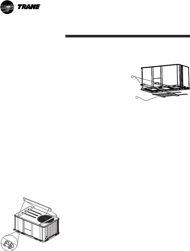
Unit handling
The units are supplied on the truck but are not unloaded. An opening is provided on each corner of the unit base to facilitate handling. Four shackles and four slings are required. Use a lifting beam to prevent the cables pressing too hard on top of the unit during lifting.The structure accommodating the unit(s) must be designed to support the equipment in operation, as a minimum. (Refer to Figures 1 and
2 and Tables 2 and 3.)
Important: For unit to fit on the roof curb the fork lift pockets must be removed.
Figure 1 - Unit handing
Roof curb (accessory)
Roof curbs are available as an accessory for downflow units. The curbs can be adjustable and supplied pre-assembled on wooden pallets, packed under plastic film. Two types of self-adhesive seals are provided to ensure the roof curb seal is leak-tight (40 mm wide for the perimeter, 20 mm wide for the crosspieces).
Roof curb Installation (TSD-WSD-YSD accessories)
Roof curbs are available as an accessory for "downflow" units to support the unit and ensure the water tightness between the rooftop and the roof.
The curbs can be adjustable and supplied pre-assembled on wooden pallets, packed under plastic film. Two types of self-adhesive seals are provided separate. (40 mm wide for the perimeter, 20 mm wide for the cross pieces). Make sure they are properly installed where indicated to assure an adequate curb to unit seal.
Instructions for the roof curb assembly and installation with curb dimensions are provided with each roof curb kit.
Figure 2 - Rigging
1
2
1 = Remove 2 fork lift brackets
2 = Remove 2 metal runners and 3 wooden boards
Lift the unit enough to allow the removal of two Fork Lift brackets and hardware. Remove the two Fork Lift brackets, two metal runners and three wooden boards as shown in Figure 2.
6 |
RT-SVX20A-E4 |
Installation
Dimensions/Weights/
Clearances
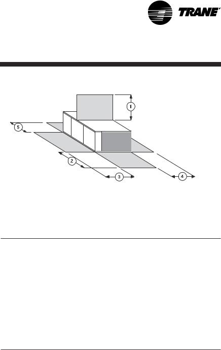
Figure 3 - Minimum clearances
The structure accommodating the unit(s) must be designed to support the equipment in operation, as a minimum. Refer to Table 2 and the space requirement plan.
Table 1 - Minimum recommended clearances
Unit size |
|
|
Mimum clearances (mm) |
|
|
|
1 |
2 |
3 |
4 |
5 |
|
|
|
|
|
|
TSD/TSH 060 |
1829 |
1219 |
914 |
914 |
914 |
TSD/TSH 072 |
1829 |
1219 |
914 |
914 |
914 |
TSD/TSH 090 |
1829 |
1219 |
914 |
914 |
914 |
TSD/TSH 102 |
1829 |
1219 |
914 |
914 |
914 |
TSD/TSH 120 |
1829 |
1219 |
914 |
914 |
914 |
|
|
|
|
|
|
YSD/YSH 060 |
1829 |
1219 |
914 |
914 |
914 |
YSD/YSH 072 |
1829 |
1219 |
914 |
914 |
914 |
YSD/YSH 090 |
1829 |
1219 |
914 |
914 |
914 |
YSD/YSH 102 |
1829 |
1219 |
914 |
914 |
914 |
YSD/YSH 120 |
1829 |
1219 |
914 |
914 |
914 |
|
|
|
|
|
|
WSD/WSH 060 |
1829 |
1219 |
914 |
914 |
914 |
WSD/WSH 072 |
1829 |
1219 |
914 |
914 |
914 |
WSD/WSH 090 |
1829 |
1219 |
914 |
914 |
914 |
|
|
|
|
|
|
Table 2 - Unit weights and center of gravity
|
Maximum weight |
|
Corner weight (1) |
|
Center of gravity |
||||
Unit Size |
|
|
|
|
|
|
|
|
|
Shipping |
Net |
A |
B |
C |
D |
Length |
Width |
||
|
|||||||||
|
(kg) |
(kg) |
(kg) |
(kg) |
(kg) |
(kg) |
(mm) |
(mm) |
|
|
|
|
|
|
|
|
|
|
|
TSD/TSH 060 |
259 |
235 |
75 |
56 |
48 |
56 |
790 |
480 |
|
TSD/TSH 072 |
365 |
326 |
107 |
83 |
58 |
78 |
970 |
560 |
|
TSD/TSH 090 |
428 |
389 |
131 |
101 |
67 |
89 |
970 |
530 |
|
TSD/TSH 102 |
445 |
405 |
133 |
106 |
72 |
94 |
990 |
560 |
|
TSD/TSH 120 |
485 |
445 |
147 |
115 |
81 |
104 |
990 |
560 |
|
|
|
|
|
|
|
|
|
|
|
YSD/YSH 060 |
285 |
260 |
81 |
64 |
54 |
62 |
810 |
510 |
|
YSD/YSH 072 |
390 |
350 |
113 |
90 |
64 |
83 |
990 |
560 |
|
YSD/YSH 090 |
458 |
419 |
139 |
110 |
75 |
95 |
970 |
530 |
|
YSD/YSH 102 |
474 |
434 |
141 |
114 |
79 |
100 |
1020 |
560 |
|
YSD/YSH 120 |
520 |
481 |
155 |
126 |
89 |
111 |
1020 |
560 |
|
|
|
|
|
|
|
|
|
|
|
WSD/WSH 060 |
266 |
241 |
77 |
58 |
49 |
58 |
790 |
480 |
|
WSD/WSH 072 |
408 |
368 |
122 |
93 |
66 |
87 |
970 |
560 |
|
WSD/WSH 090 |
418 |
378 |
128 |
95 |
67 |
88 |
970 |
530 |
|
Notes:
(1) Corner weights are given for information only. All models must be supported continuously by a curb or equivalent frame support.
RT-SVX20A-E4 |
7 |
Installation
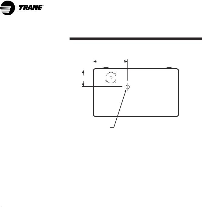
Figure 4
A |
|
|
Center of |
|
|
|
|
|
B |
|
|
gravity length |
|
|
|
||||||
|
|
|
|
|
|
|
||||
|
|
|
|
|
|
|
|
|
|
|
|
|
|
|
|
|
|
|
|
|
|
Center of gravity width
D C
Center of
gravity
Table 3 - Factory-installed options and accessories net weights (kg)
|
|
Barometric |
Motorized |
Manual |
|
Oversized |
Electric |
Hot water |
|
Unit size |
Economizer |
Outside Air |
Outside Air |
Roof Curb |
|||||
Relief |
Motor |
Heaters |
coil |
||||||
|
|
Damper |
Damper |
|
|||||
|
|
|
|
|
|
|
|||
|
|
|
|
|
|
|
|
|
|
TSD/TSH 060 |
11,8 |
3,2 |
9,1 |
7,3 |
31,8 |
- |
6,8 |
14,0 |
|
|
|
|
|
|
|
|
|
|
|
TSD/TSH 072 |
16,3 |
4,5 |
13,6 |
11,8 |
52,2 |
3,6 |
13,6 |
17,0 |
|
|
|
|
|
|
|
|
|
|
|
TSD/TSH 090 |
16,3 |
4,5 |
13,6 |
11,8 |
52,2 |
3,6 |
13,6 |
17,0 |
|
|
|
|
|
|
|
|
|
|
|
TSD/TSH 1020 |
16,3 |
4,5 |
13,6 |
11,8 |
52,2 |
3,6 |
13,6 |
19,0 |
|
|
|
|
|
|
|
|
|
|
|
TSD/TSH 120 |
16,3 |
4,5 |
13,6 |
11,8 |
52,2 |
3,6 |
13,6 |
19,0 |
|
|
|
|
|
|
|
|
|
|
|
YSD/YSH 060 |
11,8 |
3,2 |
9,1 |
7,3 |
31,8 |
- |
6,8 |
|
|
|
|
|
|
|
|
|
|
|
|
YSD/YSH 072 |
16,3 |
4,5 |
13,6 |
11,8 |
52,2 |
3,6 |
13,6 |
|
|
|
|
|
|
|
|
|
|
|
|
YSD/YSH 090 |
16,3 |
4,5 |
13,6 |
11,8 |
52,2 |
3,6 |
13,6 |
|
|
|
|
|
|
|
|
|
|
|
|
YSD/YSH 102 |
16,3 |
4,5 |
13,6 |
11,8 |
52,2 |
3,6 |
13,6 |
|
|
|
|
|
|
|
|
|
|
|
|
YSD/YSH 120 |
16,3 |
4,5 |
13,6 |
11,8 |
52,2 |
3,6 |
13,6 |
|
|
|
|
|
|
|
|
|
|
|
|
WSD/WSH 060 |
11,8 |
3,2 |
9,1 |
7,3 |
31,8 |
- |
6,8 |
14,0 |
|
|
|
|
|
|
|
|
|
|
|
WSD/WSH 072 |
16,3 |
4,5 |
13,6 |
11,8 |
52,2 |
3,6 |
13,6 |
17,0 |
|
|
|
|
|
|
|
|
|
|
|
WSD/WSH 090 |
16,3 |
4,5 |
13,6 |
11,8 |
52,2 |
3,6 |
13,6 |
17,0 |
|
|
|
|
|
|
|
|
|
|
Notes:
(1)Weights for options not listed are < 3 kg.
(2)Net weight should be added to unit weight when ordering factory-installed accessories.
(3)Some accessories are not available on all units.
8 |
RT-SVX20A-E4 |

Installation
Installing the unit
Discharge Conversion
If a unit is to be converted to Vertical discharge, a panel must be acquired from Trane.
If a unit is to be converted to Horizontal discharge, the following conversion must be performed:
1.Remove the return and supply duct covers.
2.Apply gasket to the return duct cover.
Figure 6 - Unit mounting on roof
1
1 = Frame
3.Position duct covers as shown in Figure 4. The supply duct cover is installed (insulation side down) over the downflow return opening by engaging one side of the panel under a retaining angle and securing the other side with 3 screws.
4.Slide return duct cover (insulation side up) into supply openings until outer edge of the duct cover engages with the two retaining clips on the duct flanges. Secure the outer edge of the each duct cover with two screws.
Figure 5 - Conversion to horizontal discharge
3
1
2
1 = Supply duct cover, insulation side down
2 = Return duct cover with gasket installed, insulation side up
3 = Edge of duct cover goes under retaining angle
Unit mounting on roof
Fix the rooftop curb on the joint beam of the building's structure. Make the rooftop curb's sealing surface level using angle brackets adjusted by screw bolts, located around its perimeter. Place the adhesive seals on the curb's sealing surface (perimeter and cross pieces). Make the rooftop leak-tight around the curbs before installing the unit, in compliance with current construction standards.
Note: The unit must be installed perfectly level to ensure condensates flow from the condensate tray.
The rooftop unit nests into the curb and is supported by it. Position the unit, taking care to comply with the indicated directions: the unit's discharge and intake openings must match those of the curb.
RT-SVX20A-E4 |
9 |
Installation
Installing the unit on the ground
To install the unit on the ground, its base must be level and supported securely. For horizontal discharge units, a support is required such as a metal or concrete slab whose height must be determined according to the amount of snow cover, to prevent problems with condensation drainage and obstruction of the external coil. If necessary use an anti-vibration material between the rooftop unit's base and the support.
Note: Unit installation must comply to local codes
Connection of duct network
1) Downflow discharge units (TSD,WSD,YSD)
Using the rooftop curb
•The rooftop curb must be insulated on the outside walls at the discharge and intake openings to prevent condensation in the ducts.
•The rims around the discharge and intake openings make it possible to attach the flanges on the ends of the ducts. If you are using rigid duct ends recommended on the rooftop curb plan, it is essential to fix these components before installing the unit.
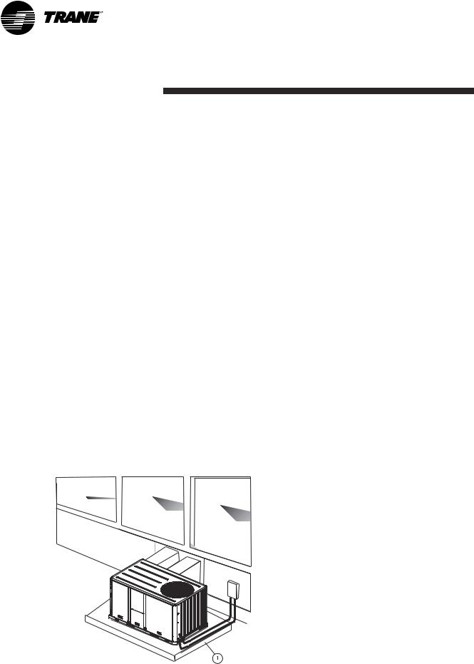
Figure 7 - Unit installation on the ground
1 = Concrete slab
•For the design of the duct network, comply with recommendations currently applicable on the market, in particular:
. Installation of a section of flexible ducts to limit transmission of the unit's vibrations
. Use of movable vanes or deflectors to reduce the sound level.
2) Horizontal discharge units (TSH,WSH,YSH)
•The intake and discharge ducts must be insulated (thermal insulation).
•The duct section located outside must be leak-tight.
•Provide a flexible connector to prevent transmission of the unit vibrations. This flexible duct must be installed inside the building.
Note: In case of use of units with economizer option, temperature and humidity sensors must be installed in return duct.
Economizer linkage is factory mounted but the damper position must be adjusted on site.
10 |
RT-SVX20A-E4 |
Installation
Table 4 - Duct dimensions for downflow units (mm)
Unit size |
A |
B |
C |
D |
E |
Flanges |
|
|
|
|
|
|
|
TSD 060 |
619 |
357 |
411 |
459 |
356 |
32 |
|
|
|
|
|
|
|
YSD 060 |
610 |
356 |
394 |
457 |
356 |
32 |
|
|
|
|
|
|
|
WSD 060 |
819 |
357 |
411 |
459 |
356 |
32 |
|
|
|
|
|
|
|
TSD/WSD 072/090 |
875 |
451 |
451 |
875 |
356 |
31 |
|
|
|
|
|
|
|
TSD 102/120 |
875 |
451 |
451 |
875 |
356 |
31 |
|
|
|
|
|
|
|
YSD 072/090/102/120 |
816 |
444 |
444 |
838 |
356 |
31 |
|
|
|
|
|
|
|
Table 5 - Duct dimensions for downflow units (mm)
Unit size |
A |
B |
C |
D |
|
|
|
|
|
TSH/WSH 060 |
591 |
337 |
375 |
438 |
|
|
|
|
|
YSH 060 |
591 |
337 |
375 |
438 |
|
|
|
|
|
TSH/WSH/YSH 072/090 |
832 |
425 |
606 |
489 |
|
|
|
|
|
TSH/YSH 102/120 |
832 |
425 |
606 |
489 |
|
|
|
|
|
Figure 8 - Duct dimensions for downflow units |
Figure 9 - Duct dimensions for horizontal units |
|
|
|
B |
|
|
A |
C |
|
|
|
|
|
|
|
|
D |
|
|
|
R |
A |
S |
R |
|
|
S C |
|
||
|
|
B |
|
E |
|
D |
|
|
|
|
|
S = Supply |
|
S = Supply |
|
R = Return |
|
R = Return |
|
RT-SVX20A-E4 |
11 |
Installation
Condensate drain piping
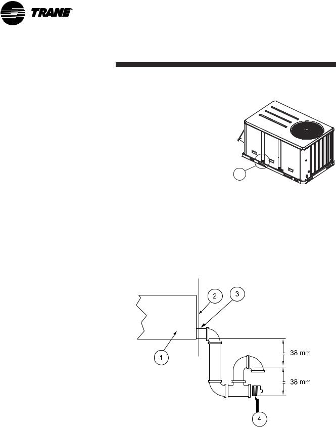
A 3/4" condensate drain connection with P-trap is provided. Follow local codes and standard piping practices when running the drain line. Install a trap and be sure to fill with water before starting the unit. Pitch the line downward, away from the unit to avoid long, level, horizontal runs. Refer to Figure 11.
The condensate drain is reversible to allow installation of a drain tap on either side of the unit.
Figure 10 - Condensate drain location
1
1 = Main condensate drain location
Figure 11 - Condensate drain line location
1 = Static pressure drain pan
2 = Panel enclosure
3 = ¾ " drain
4 = Cleanout plug
12 |
RT-SVX20A-E4 |
Installation
Gas pipework installation
The installation must conform to all standards and regulations.
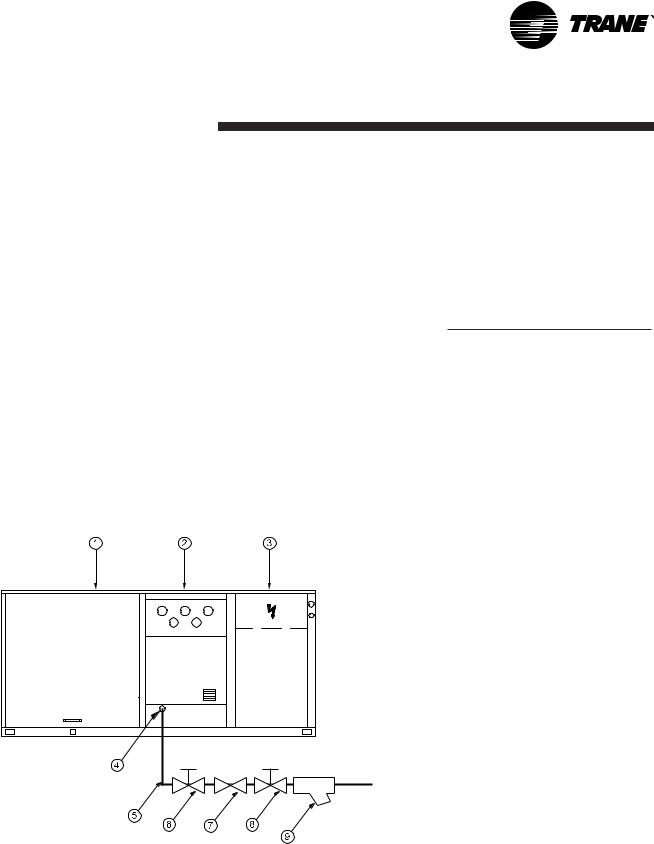
The gas supply pipework and gas stop valve to be installed near the unit must be sized so as to ensure the gas pressure is sufficient at the unit inlet when operating at full load.
CAUTION! Should the pressure at the unit valve gas inlet be higher than 0.035 bar, an expansion valve must be installed.
The pipework must be selfsupporting and the final connection to the burner must be made by a flexible pipe. Provide a dust protection (filter) upstream the unit connection.
Figure 12 - Typical gas supply pipework
CAUTION! The gas pipework must not exert any stress on the burner gas connection.
Note: Expansion valve must be adapted to the type of gas used:
•G 20: 20 mb
•G 25: 25 mb
•G 31 (Propane): 37 or 50 mb
Table 6 - Gas burner models
Unit |
Burner size |
|
|
YSD/YSH 060 |
G120 |
|
|
YSD/YSH 072 |
G200 |
|
|
YSD/YSH 090 |
G200 |
|
|
YSD/YSH 102 |
G250 |
|
|
YSD/YSH 120 |
G250 |
|
|
See Table 51 for burner performance.
Gas leak check procedure
1.Vent the gas line
2.Gas supply line pressure test: close valve 4 and open valve 2
3.Leak-check the gas pipe.
Look for gas pipe leaks using "Typol", "1000 bulles" or a similar product. Do not use soapy water.
WARNING! Never use an open flame to check for gas leaks.
Required gas pressure at the unit inlet connection are given in Table 50.
Note: To operate with propane gas, the burner is fitted with a pressure limiter (supplied by Trane)
1 = Evaporator section
2 = Gas burner section
3 = Condenser section
4 = Gas supply connection
5 = Gas supply line
6, 8 = Gas stop valve (Field supplied) 7 = Expansion valve (Field supplied) 9 = Filter (Field supplied)
RT-SVX20A-E4 |
13 |

Installation
Filter installation
To gain access to filters, remove the supply fan access panel on downflow units and the filter access panel on the end for horizontal units.
Number and size of filters is determined by size and configuration of the unit. If disposable filters were chosen as an option, they are shipped in the supply fan section.
CAUTION! Do not operate unit without filters in place.
The maximum pressure drops allowable on filters are:
EU2/G2: 120 Pa
EU4/G4: 150 Pa
Supply fan adjustment
Use the following procedure to determine the proper adjustment of the supply fan for a specific application.
1.Determine total external static pressure about system and accessories.
•Obtain the design airflow rate and the design external static pressure drop through the distribution system.
•Add static pressure drop of the accessories installed on the unit. (Table 9)
•Add the total accessory static pressure drop (from step 1b) to the design external static pressure (from step 1a). The sum of these two values is the total system external static pressure.
2.Using the Tables 10 through 35 to find the external static pressure that most closely approximates total system external static pressure. Then locate the appropriate airflow rate for your unit. The value obtained represents the brake horsepower for the supply fan motor and the fan RPM.
3.Adjust motor sheave according to Table 8.
Table 7 - Filter arrangement
Unit |
|
EU2/G2 |
|
EU4/G4 |
|
|
|
|
|
||
Quantity |
Size |
Quantity |
Size |
||
|
|||||
|
|
|
|
|
|
TSD/TSH/YSD/YSH/WSD/WSH 060 |
2 |
(508x762x25) |
2 |
(500x750x25) |
|
|
|
|
|
|
|
TSD/TSH/YSD/YSH/WSD/WSH 072 |
4 |
(406x635x50) |
4 |
(395x625x50) |
|
|
|
|
|
|
|
TSD/TSH/YSD/YSH/WSD/WSH 090 |
4 |
(406x635x50) |
4 |
(395x625x50) |
|
|
|
|
|
|
|
TSD/TSH/YSD/YSH 102 |
4 |
(508x635x50) |
4 |
(500x625x50) |
|
|
|
|
|
|
|
TSD/TSH/YSD/YSH 120 |
4 |
(508x635x50) |
4 |
(500x625x50) |
|
|
|
|
|
|
14 |
RT-SVX20A-E4 |

Installation
To increase airflow
Loosen variable sheave set screw and turn sheave clockwise.
To decrease airflow
Loosen variable sheave set screw and turn sheave counter-clockwise.
To adjust belt
The fan belts must be inspected periodically to assure proper unit operation. Replacement is necessary if the belts appear frayed or worn.
Units with dual belts require a matched set of belts to ensure equal belt length.
When removing or installing the new belts, do not stretch them over the sheaves. Loosen the belts using the belt tension adjustment bolts on the motor mounting base.
Once the new belts are installed, adjust the belt tension.
Table 8 - Motor sheave / Fan speed
|
|
|
|
Fan speed (RPM) |
|
|
|
|
|
|
|
|
Standard drive & motor |
|
|
|
|
|
|
|
|
|
|
|
|
|
Unit |
6 turns |
5 turns |
4 turns |
3 turns |
2 turns |
1 turns |
Closed |
|
Open |
Open |
Open |
Open |
Open |
Open |
|||
|
|
|||||||
|
|
|
|
|
|
|
|
|
TSD/TSH 060 |
N/A |
898 |
967 |
1036 |
1105 |
1174 |
1243 |
|
|
|
|
|
|
|
|
|
|
TSD/TSH 072 |
N/A |
698 |
751 |
806 |
859 |
913 |
967 |
|
|
|
|
|
|
|
|
|
|
TSD/TSH 090 |
N/A |
752 |
806 |
860 |
914 |
968 |
1020 |
|
|
|
|
|
|
|
|
|
|
TSD/TSH 102 |
N/A |
688 |
737 |
786 |
835 |
885 |
934 |
|
|
|
|
|
|
|
|
|
|
TSD/TSH 120 |
N/A |
782 |
838 |
894 |
950 |
1006 |
1062 |
|
|
|
|
|
|
|
|
|
|
YSD/YSH 060 |
N/A |
1036 |
1105 |
1174 |
1243 |
1312 |
1381 |
|
|
|
|
|
|
|
|
|
|
YSD/YSH 072 |
N/A |
806 |
860 |
913 |
968 |
1022 |
1074 |
|
|
|
|
|
|
|
|
|
|
YSD/YSH 090 |
859 |
913 |
967 |
1021 |
1075 |
1129 |
N/A |
|
|
|
|
|
|
|
|
|
|
YSD/YSH 102 |
786 |
836 |
885 |
934 |
982 |
1032 |
N/A |
|
|
|
|
|
|
|
|
|
|
YSD/YSH 120 |
894 |
950 |
1006 |
1062 |
1118 |
1174 |
N/A |
|
|
|
|
|
|
|
|
|
|
WSD/WSH 060 |
N/A |
898 |
967 |
1036 |
1105 |
1174 |
1243 |
|
|
|
|
|
|
|
|
|
|
WSD/WSH 072 |
N/A |
698 |
751 |
806 |
859 |
913 |
967 |
|
|
|
|
|
|
|
|
|
|
WSD/WSH 090 |
N/A |
752 |
806 |
860 |
914 |
968 |
1020 |
|
|
|
|
|
|
|
|
|
|
|
|
|
|
|
|
|
|
|
|
|
|
|
Fan speed (RPM) |
|
|
|
|
|
|
|
|
Oversized drive & motor |
|
|
|
|
|
|
|
|
|
|
|
|
|
Unit |
6 turns |
5 turns |
4 turns |
3 turns |
2 turns |
1 turns |
Closed |
|
Open |
Open |
Open |
Open |
Open |
Open |
|||
|
|
|||||||
|
|
|
|
|
|
|
|
|
TSD/TSH 060 |
N/A |
1243 |
1311 |
1379 |
1450 |
1515 |
1588 |
|
|
|
|
|
|
|
|
|
|
TSD/TSH 072 |
N/A |
967 |
1021 |
1075 |
1128 |
1183 |
1235 |
|
|
|
|
|
|
|
|
|
|
TSD/TSH 090 |
1112 |
1182 |
1252 |
1322 |
1392 |
1460 |
N/A |
|
|
|
|
|
|
|
|
|
|
TSD/TSH 102 |
N/A |
971 |
1041 |
1111 |
1181 |
1251 |
1321 |
|
|
|
|
|
|
|
|
|
|
TSD/TSH 120 |
1062 |
1118 |
1174 |
1229 |
1285 |
1341 |
N/A |
|
|
|
|
|
|
|
|
|
|
YSD/YSH 060 |
- |
- |
- |
- |
- |
- |
- |
|
|
|
|
|
|
|
|
|
|
YSD/YSH 072 |
N/A |
967 |
1021 |
1075 |
1128 |
1183 |
1235 |
|
|
|
|
|
|
|
|
|
|
YSD/YSH 090 |
1112 |
1182 |
1252 |
1322 |
1392 |
1460 |
N/A |
|
|
|
|
|
|
|
|
|
|
YSD/YSH 102 |
N/A |
971 |
1041 |
1111 |
1181 |
1251 |
1321 |
|
|
|
|
|
|
|
|
|
|
YSD/YSH 120 |
1062 |
1118 |
1174 |
1229 |
1285 |
1341 |
N/A |
|
|
|
|
|
|
|
|
|
|
WSD/WSH 060 |
N/A |
1243 |
1311 |
1379 |
1450 |
1515 |
1588 |
|
|
|
|
|
|
|
|
|
|
WSD/WSH 072 |
N/A |
967 |
1021 |
1075 |
1128 |
1183 |
1235 |
|
|
|
|
|
|
|
|
|
|
WSD/WSH 090 |
1112 |
1182 |
1252 |
1322 |
1392 |
1460 |
N/A |
|
|
|
|
|
|
|
|
|
RT-SVX20A-E4 |
15 |

Installation
Component air pressure drops
Table 9 - Pressure drop through accessories
Unit |
Airflow |
Filter |
Filter |
Economizer |
Electric |
Hot water |
|
100% |
|||||||
size |
(m3/h) |
EU2/G2 |
EU4/G4 |
heater |
coil |
||
|
|
|
|
outside air |
|
|
|
|
|
|
|
|
|
|
|
|
3060 |
31 |
50 |
38 |
17 |
49 |
|
|
|
|
|
|
|
|
|
060 |
3400 |
38 |
55 |
46 |
21 |
55 |
|
|
|
|
|
|
|
||
3740 |
46 |
61 |
55 |
25 |
62 |
||
|
|||||||
|
|
|
|
|
|
|
|
|
4080 |
55 |
66 |
64 |
30 |
68 |
|
|
|
|
|
|
|
|
|
|
|
|
|
|
|
|
|
|
3670 |
13 |
37 |
27 |
7 |
46 |
|
|
|
|
|
|
|
|
|
072 |
4080 |
16 |
42 |
29 |
9 |
52 |
|
|
|
|
|
|
|
||
4490 |
19 |
46 |
31 |
11 |
58 |
||
|
|||||||
|
|
|
|
|
|
|
|
|
4900 |
23 |
50 |
33 |
13 |
64 |
|
|
|
|
|
|
|
|
|
|
|
|
|
|
|
|
|
|
4590 |
19 |
47 |
33 |
12 |
66 |
|
|
|
|
|
|
|
|
|
090 |
5100 |
24 |
52 |
39 |
15 |
74 |
|
|
|
|
|
|
|
||
5610 |
29 |
57 |
45 |
20 |
83 |
||
|
|||||||
|
|
|
|
|
|
|
|
|
6120 |
35 |
62 |
52 |
25 |
92 |
|
|
|
|
|
|
|
|
|
|
|
|
|
|
|
|
|
|
5200 |
16 |
42 |
40 |
8 |
64 |
|
|
|
|
|
|
|
|
|
102 |
5780 |
20 |
47 |
50 |
10 |
72 |
|
|
|
|
|
|
|
||
6360 |
25 |
52 |
62 |
12 |
81 |
||
|
|||||||
|
|
|
|
|
|
|
|
|
6940 |
30 |
57 |
75 |
15 |
90 |
|
|
|
|
|
|
|
|
|
|
|
|
|
|
|
|
|
|
6120 |
22 |
50 |
52 |
11 |
84 |
|
|
|
|
|
|
|
|
|
120 |
6800 |
27 |
55 |
62 |
14 |
95 |
|
|
|
|
|
|
|
||
7480 |
33 |
61 |
73 |
17 |
106 |
||
|
|||||||
|
|
|
|
|
|
|
|
|
8160 |
40 |
66 |
85 |
20 |
117 |
|
|
|
|
|
|
|
|
16 |
RT-SVX20A-E4 |
Installation
Supply fan performances
Table 10 - TSD 060 Available static pressure
External Static Pressure (Pa)
|
25 |
|
50 |
|
75 |
|
100 |
125 |
150 |
175 |
200 |
225 |
250 |
275 |
300 |
|||||||||
|
|
|
|
|
|
|
|
|
|
|
|
|
|
|
|
|
|
|
|
|
|
|
|
|
m3/h |
RPM |
kW |
RPM |
kW |
RPM |
kW |
RPM |
kW |
RPM |
kW |
RPM |
kW |
RPM |
kW |
RPM |
kW |
RPM |
kW |
RPM |
kW |
Fan |
kW |
Fan |
kW |
|
|
|
|
|
|
|
|
|
|
|
|
|
|
|
|
|
|
|
|
|
RPM |
|
RPM |
|
|
|
|
|
|
|
|
|
|
|
|
|
|
|
|
|
|
|
|
|
|
|
|
|
|
2720 |
- |
- |
- |
- |
- |
- |
- |
- |
- |
- |
899 |
0.43 |
944 |
0.49 |
985 |
0.54 |
1023 |
0.59 |
1060 |
0.64 |
1093 |
0.69 |
1126 |
0.74 |
|
|
|
|
|
|
|
|
|
|
|
|
|
|
|
|
|
|
|
|
|
|
|
|
|
3060 |
- |
- |
- |
- |
- |
- |
- |
- |
904 |
0.49 |
947 |
0.54 |
988 |
0.58 |
1028 |
0.64 |
1067 |
0.70 |
1104 |
0.76 |
1138 |
0.82 |
1171 |
0.87 |
|
|
|
|
|
|
|
|
|
|
|
|
|
|
|
|
|
|
|
|
|
|
|
|
|
3400 |
- |
- |
- |
- |
- |
- |
918 |
0.57 |
958 |
0.62 |
998 |
0.67 |
1036 |
0.71 |
1073 |
0.76 |
1111 |
0.82 |
1147 |
0.89 |
1182 |
0.96 |
1215 |
1.02 |
|
|
|
|
|
|
|
|
|
|
|
|
|
|
|
|
|
|
|
|
|
|
|
|
|
3740 |
- |
- |
- |
- |
930 |
0.65 |
977 |
0.71 |
1016 |
0.77 |
1053 |
0.82 |
1089 |
0.88 |
1124 |
0.93 |
1158 |
0.98 |
1191 |
1.03 |
1226 |
1.10 |
1258 |
1.17 |
4080 |
909 |
0.71 |
950 |
0.76 |
990 |
0.80 |
1034 |
0.87 |
1074 |
0.93 |
1110 |
1.00 |
1143 |
1.06 |
1177 |
1.12 |
1209 |
1.17 |
1241 |
1.23 |
1272 |
1.29 |
- |
- |
|
|
|
|
|
|
|
|
|
|
|
|
|
|
|
|
|
|
|
|
|
|
|
|
|
|
325 |
350 |
375 |
|
|||
|
|
|
|
|
|
|
|
m3/h |
Fan |
kW |
Fan |
kW |
Fan |
kW |
|
|
RPM |
|
RPM |
|
RPM |
|
|
|
|
|
|
|
|
|
|
2720 |
1160 |
0.79 |
1190 |
0.84 |
1222 |
0.90 |
|
|
|
|
|
|
|
|
|
3060 |
1203 |
0.93 |
1232 |
0.98 |
1262 |
1.04 |
|
3400 |
1246 |
1.09 |
1276 |
1.15 |
1306 |
1.21 |
|
3740 |
1290 |
1.25 |
- |
- |
- |
- |
|
4080 |
- |
- |
- |
- |
- |
- |
|
|
|
|
|
|
|
|
|
Table 11 - TSH 060 Available static pressure
External Static Pressure (Pa)
|
25 |
|
50 |
|
75 |
|
100 |
125 |
150 |
175 |
200 |
225 |
250 |
275 |
300 |
|||||||||
|
|
|
|
|
|
|
|
|
|
|
|
|
|
|
|
|
|
|
|
|
|
|
|
|
m3/h |
RPM |
kW |
RPM |
kW |
RPM |
kW |
RPM |
kW |
RPM |
kW |
RPM |
kW |
RPM |
kW |
RPM |
kW |
RPM |
kW |
RPM |
kW |
Fan |
kW |
Fan |
kW |
|
|
|
|
|
|
|
|
|
|
|
|
|
|
|
|
|
|
|
|
|
RPM |
|
RPM |
|
|
|
|
|
|
|
|
|
|
|
|
|
|
|
|
|
|
|
|
|
|
|
|
|
|
2720 |
- |
- |
- |
- |
- |
- |
898 |
0.43 |
953 |
0.48 |
1001 |
0.54 |
1045 |
0.59 |
1087 |
0.65 |
1129 |
0.71 |
1168 |
0.77 |
1206 |
0.83 |
1241 |
0.89 |
|
|
|
|
|
|
|
|
|
|
|
|
|
|
|
|
|
|
|
|
|
|
|
|
|
3060 |
- |
- |
- |
- |
897 |
0.48 |
953 |
0.54 |
1008 |
0.60 |
1058 |
0.67 |
1102 |
0.73 |
1143 |
0.79 |
1181 |
0.85 |
1219 |
0.92 |
1256 |
0.99 |
1291 |
1.05 |
3400 |
- |
- |
908 |
0.54 |
961 |
0.60 |
1012 |
0.67 |
1062 |
0.74 |
1111 |
0.81 |
1157 |
0.88 |
1198 |
0.95 |
1237 |
1.02 |
1274 |
1.09 |
1309 |
1.16 |
1343 |
1.24 |
3740 |
923 |
0.63 |
978 |
0.69 |
1028 |
0.76 |
1075 |
0.83 |
1120 |
0.91 |
1166 |
0.99 |
1211 |
1.06 |
1254 |
1.14 |
1294 |
1.22 |
1330 |
1.29 |
- |
- |
- |
- |
4080 |
997 |
0.80 |
1049 |
0.87 |
1096 |
0.94 |
1140 |
1.02 |
1183 |
1.10 |
1223 |
1.18 |
1266 |
1.27 |
- |
- |
- |
- |
- |
- |
- |
- |
- |
- |
|
|
|
|
|
|
|
|
|
|
|
|
|
|
|
|
|
|
|
|
|
|
|
|
|
|
325 |
350 |
375 |
|
|||
|
|
|
|
|
|
|
|
m3/h |
Fan |
kW |
Fan |
kW |
Fan |
kW |
|
|
RPM |
|
RPM |
|
RPM |
|
|
|
|
|
|
|
|
|
|
2720 |
1275 |
0.96 |
1306 |
1.02 |
1338 |
1.09 |
|
3060 |
1326 |
1.12 |
1359 |
1.19 |
1390 |
1.26 |
|
3400 |
1376 |
1.31 |
- |
- |
- |
- |
|
3740 |
- |
- |
- |
- |
- |
- |
|
|
|
|
|
|
|
|
|
4080 |
- |
- |
- |
- |
- |
- |
|
|
|
|
|
|
|
|
|
Standard drive
Oversize drive Note : Data includes pressure drops for standard filters and wet coils
RT-SVX20A-E4 |
17 |

Installation
Table 12 - TSD 072 Available static pressure
External Static Pressure (Pa)
|
25 |
|
50 |
|
75 |
|
100 |
125 |
150 |
175 |
200 |
225 |
250 |
275 |
300 |
|||||||||
|
|
|
|
|
|
|
|
|
|
|
|
|
|
|
|
|
|
|
|
|
|
|
|
|
m3/h |
RPM |
kW |
RPM |
kW |
RPM |
kW |
RPM |
kW |
RPM |
kW |
RPM |
kW |
RPM |
kW |
RPM |
kW |
RPM |
kW |
RPM |
kW |
Fan |
kW |
Fan |
kW |
|
|
|
|
|
|
|
|
|
|
|
|
|
|
|
|
|
|
|
|
|
RPM |
|
RPM |
|
|
|
|
|
|
|
|
|
|
|
|
|
|
|
|
|
|
|
|
|
|
|
|
|
|
3260 |
- |
- |
- |
- |
- |
- |
- |
- |
- |
- |
726 |
0.41 |
769 |
0.47 |
811 |
0.52 |
851 |
0.58 |
889 |
0.65 |
925 |
0.71 |
960 |
0.77 |
|
|
|
|
|
|
|
|
|
|
|
|
|
|
|
|
|
|
|
|
|
|
|
|
|
3670 |
- |
- |
- |
- |
- |
- |
- |
- |
706 |
0.43 |
751 |
0.49 |
792 |
0.55 |
832 |
0.61 |
871 |
0.67 |
908 |
0.74 |
944 |
0.81 |
978 |
0.87 |
4080 |
- |
- |
- |
- |
- |
- |
- |
- |
732 |
0.51 |
777 |
0.58 |
818 |
0.64 |
856 |
0.71 |
893 |
0.77 |
930 |
0.84 |
964 |
0.91 |
998 |
0.99 |
4490 |
- |
- |
- |
- |
- |
- |
715 |
0.54 |
758 |
0.60 |
802 |
0.68 |
845 |
0.75 |
883 |
0.82 |
919 |
0.89 |
953 |
0.96 |
986 |
1.04 |
1019 |
1.11 |
4890 |
- |
- |
- |
- |
706 |
0.58 |
749 |
0.64 |
789 |
0.71 |
830 |
0.79 |
870 |
0.87 |
909 |
0.95 |
945 |
1.02 |
979 |
1.10 |
1011 |
1.18 |
1043 |
1.26 |
|
|
|
|
|
|
|
|
|
|
|
|
|
|
|
|
|
|
|
|
|
|
|
|
|
|
325 |
350 |
375 |
|
|||
|
|
|
|
|
|
|
|
m3/h |
Fan |
kW |
Fan |
kW |
Fan |
kW |
|
|
RPM |
|
RPM |
|
RPM |
|
|
|
|
|
|
|
|
|
|
3260 |
994 |
0.83 |
1026 |
0.89 |
1057 |
0.95 |
|
3670 |
1010 |
0.94 |
1043 |
1.01 |
1073 |
1.08 |
|
4080 |
1030 |
1.06 |
1063 |
1.14 |
1092 |
1.21 |
|
4490 |
1051 |
1.19 |
1082 |
1.27 |
1112 |
1.35 |
|
4890 |
1073 |
1.34 |
1103 |
1.42 |
1133 |
1.51 |
|
|
|
|
|
|
|
|
|
Table 13 - TSH 072 Available static pressure
External Static Pressure (Pa)
|
25 |
|
50 |
|
75 |
|
100 |
125 |
150 |
175 |
200 |
225 |
250 |
275 |
300 |
|||||||||
|
|
|
|
|
|
|
|
|
|
|
|
|
|
|
|
|
|
|
|
|
|
|
|
|
m3/h |
RPM |
kW |
RPM |
kW |
RPM |
kW |
RPM |
kW |
RPM |
kW |
RPM |
kW |
RPM |
kW |
RPM |
kW |
RPM |
kW |
RPM |
kW |
Fan |
kW |
Fan |
kW |
|
|
|
|
|
|
|
|
|
|
|
|
|
|
|
|
|
|
|
|
|
RPM |
|
RPM |
|
|
|
|
|
|
|
|
|
|
|
|
|
|
|
|
|
|
|
|
|
|
|
|
|
|
3260 |
- |
- |
- |
- |
- |
- |
- |
- |
726 |
0.39 |
771 |
0.45 |
814 |
0.51 |
857 |
0.57 |
899 |
0.63 |
939 |
0.70 |
978 |
0.76 |
1015 |
0.83 |
3670 |
- |
- |
- |
- |
- |
- |
716 |
0.42 |
762 |
0.48 |
804 |
0.54 |
843 |
0.60 |
883 |
0.67 |
922 |
0.74 |
960 |
0.81 |
996 |
0.87 |
1034 |
0.95 |
4080 |
- |
- |
- |
- |
701 |
0.45 |
751 |
0.51 |
798 |
0.59 |
839 |
0.65 |
877 |
0.71 |
914 |
0.78 |
950 |
0.85 |
984 |
0.93 |
1020 |
1.00 |
1055 |
1.08 |
4490 |
- |
- |
710 |
0.51 |
745 |
0.56 |
788 |
0.62 |
833 |
0.69 |
875 |
0.77 |
914 |
0.85 |
949 |
0.91 |
984 |
0.98 |
1016 |
1.06 |
1049 |
1.14 |
1081 |
1.23 |
4890 |
726 |
0.58 |
762 |
0.64 |
795 |
0.70 |
828 |
0.76 |
869 |
0.82 |
911 |
0.91 |
950 |
0.99 |
986 |
1.07 |
1019 |
1.14 |
1051 |
1.22 |
1081 |
1.30 |
1112 |
1.38 |
|
|
|
|
|
|
|
|
|
|
|
|
|
|
|
|
|
|
|
|
|
|
|
|
|
|
325 |
350 |
375 |
|
|||
|
|
|
|
|
|
|
|
m3/h |
Fan |
kW |
Fan |
kW |
Fan |
kW |
|
|
RPM |
|
RPM |
|
RPM |
|
|
|
|
|
|
|
|
|
|
3260 |
1051 |
0.90 |
1086 |
0.97 |
1118 |
1.04 |
|
3670 |
1069 |
1.02 |
1103 |
1.09 |
1136 |
1.17 |
|
4080 |
1089 |
1.16 |
1122 |
1.23 |
1154 |
1.31 |
|
4490 |
1113 |
1.31 |
1144 |
1.40 |
1176 |
1.48 |
|
4890 |
1141 |
1.47 |
1170 |
1.57 |
1199 |
1.66 |
|
|
|
|
|
|
|
|
|
Standard drive
|
Oversize drive |
Note : Data includes pressure drops for standard filters and wet coils |
18 |
RT-SVX20A-E4 |

Installation
Table 14 - TSD 090 Available static pressure
External Static Pressure (Pa)
|
25 |
|
50 |
|
75 |
|
100 |
125 |
150 |
175 |
200 |
225 |
250 |
275 |
300 |
|||||||||
|
|
|
|
|
|
|
|
|
|
|
|
|
|
|
|
|
|
|
|
|
|
|
|
|
m3/h |
RPM |
kW |
RPM |
kW |
RPM |
kW |
RPM |
kW |
RPM |
kW |
RPM |
kW |
RPM |
kW |
RPM |
kW |
RPM |
kW |
RPM |
kW |
Fan |
kW |
Fan |
kW |
|
|
|
|
|
|
|
|
|
|
|
|
|
|
|
|
|
|
|
|
|
RPM |
|
RPM |
|
|
|
|
|
|
|
|
|
|
|
|
|
|
|
|
|
|
|
|
|
|
|
|
|
|
4080 |
- |
- |
- |
- |
- |
- |
- |
- |
750 |
0.54 |
794 |
0.60 |
834 |
0.67 |
873 |
0.73 |
909 |
0.80 |
945 |
0.87 |
980 |
0.95 |
1013 |
1.02 |
|
|
|
|
|
|
|
|
|
|
|
|
|
|
|
|
|
|
|
|
|
|
|
|
|
4590 |
- |
- |
- |
- |
- |
- |
- |
- |
787 |
0.66 |
830 |
0.74 |
871 |
0.82 |
908 |
0.89 |
943 |
0.96 |
977 |
1.04 |
1010 |
1.11 |
1043 |
1.19 |
5100 |
- |
- |
- |
- |
747 |
0.68 |
789 |
0.74 |
827 |
0.82 |
867 |
0.90 |
906 |
0.98 |
944 |
1.06 |
980 |
1.15 |
1013 |
1.23 |
1045 |
1.31 |
1076 |
1.39 |
5610 |
- |
- |
755 |
0.77 |
797 |
0.85 |
836 |
0.92 |
873 |
1.00 |
908 |
1.08 |
944 |
1.17 |
980 |
1.26 |
1016 |
1.35 |
1050 |
1.45 |
1081 |
1.54 |
1111 |
1.63 |
6120 |
771 |
0.88 |
809 |
0.96 |
848 |
1.06 |
885 |
1.14 |
921 |
1.22 |
954 |
1.30 |
986 |
1.39 |
1019 |
1.49 |
1052 |
1.58 |
1085 |
1.69 |
1116 |
1.79 |
1148 |
1.89 |
|
|
|
|
|
|
|
|
|
|
|
|
|
|
|
|
|
|
|
|
|
|
|
|
|
|
325 |
350 |
375 |
|
|||
|
|
|
|
|
|
|
|
m3/h |
Fan |
kW |
Fan |
kW |
Fan |
kW |
|
|
RPM |
|
RPM |
|
RPM |
|
|
|
|
|
|
|
|
|
|
4080 |
1046 |
1.10 |
1076 |
1.17 |
1106 |
1.25 |
|
4590 |
1074 |
1.27 |
1105 |
1.36 |
1134 |
1.44 |
|
5100 |
1105 |
1.47 |
1134 |
1.56 |
1163 |
1.65 |
|
5610 |
1141 |
1.72 |
1168 |
1.80 |
1197 |
1.90 |
|
6120 |
1177 |
1.99 |
1204 |
2.08 |
1232 |
2.18 |
|
|
|
|
|
|
|
|
|
Table 15 - TSH 090 Available static pressure
External Static Pressure (Pa)
|
25 |
|
50 |
|
75 |
|
100 |
125 |
150 |
175 |
200 |
225 |
250 |
275 |
300 |
|||||||||
|
|
|
|
|
|
|
|
|
|
|
|
|
|
|
|
|
|
|
|
|
|
|
|
|
m3/h |
RPM |
kW |
RPM |
kW |
RPM |
kW |
RPM |
kW |
RPM |
kW |
RPM |
kW |
RPM |
kW |
RPM |
kW |
RPM |
kW |
RPM |
kW |
Fan |
kW |
Fan |
kW |
|
|
|
|
|
|
|
|
|
|
|
|
|
|
|
|
|
|
|
|
|
RPM |
|
RPM |
|
|
|
|
|
|
|
|
|
|
|
|
|
|
|
|
|
|
|
|
|
|
|
|
|
|
4080 |
- |
- |
- |
- |
- |
- |
769 |
0.54 |
814 |
0.61 |
855 |
0.67 |
893 |
0.73 |
929 |
0.81 |
965 |
0.88 |
999 |
0.96 |
1035 |
1.04 |
1070 |
1.12 |
4590 |
- |
- |
- |
- |
773 |
0.62 |
817 |
0.68 |
862 |
0.76 |
904 |
0.85 |
941 |
0.92 |
975 |
0.98 |
1009 |
1.06 |
1041 |
1.14 |
1073 |
1.22 |
1104 |
1.31 |
5100 |
771 |
0.68 |
805 |
0.74 |
837 |
0.81 |
870 |
0.87 |
912 |
0.94 |
951 |
1.03 |
989 |
1.12 |
1025 |
1.21 |
1056 |
1.28 |
1088 |
1.36 |
1117 |
1.44 |
1146 |
1.53 |
5610 |
842 |
0.89 |
873 |
0.96 |
903 |
1.03 |
930 |
1.10 |
963 |
1.17 |
1000 |
1.25 |
1037 |
1.34 |
1073 |
1.45 |
1106 |
1.55 |
1136 |
1.63 |
1165 |
1.72 |
1194 |
1.80 |
6120 |
913 |
1.14 |
942 |
1.22 |
970 |
1.30 |
996 |
1.37 |
1021 |
1.45 |
1052 |
1.52 |
1086 |
1.61 |
1121 |
1.71 |
1153 |
1.82 |
1184 |
1.93 |
1215 |
2.04 |
1242 |
2.13 |
|
|
|
|
|
|
|
|
|
|
|
|
|
|
|
|
|
|
|
|
|
|
|
|
|
|
325 |
350 |
375 |
|
|||
|
|
|
|
|
|
|
|
m3/h |
Fan |
kW |
Fan |
kW |
Fan |
kW |
|
|
RPM |
|
RPM |
|
RPM |
|
|
|
|
|
|
|
|
|
|
4080 |
1104 |
1.19 |
1137 |
1.27 |
1168 |
1.35 |
|
4590 |
1136 |
1.40 |
1167 |
1.48 |
1198 |
1.57 |
|
5100 |
1176 |
1.62 |
1205 |
1.72 |
1233 |
1.82 |
|
5610 |
1220 |
1.88 |
1248 |
1.98 |
1275 |
2.08 |
|
6120 |
1269 |
2.22 |
1295 |
2.31 |
1319 |
2.40 |
|
|
|
|
|
|
|
|
|
Standard drive
|
Oversize drive |
Note : Data includes pressure drops for standard filters and wet coils |
RT-SVX20A-E4 |
19 |

Installation
Table 16 - TSD 102 Available static pressure
External Static Pressure (Pa)
|
25 |
|
50 |
|
75 |
|
100 |
125 |
150 |
175 |
200 |
225 |
250 |
275 |
300 |
|||||||||
|
|
|
|
|
|
|
|
|
|
|
|
|
|
|
|
|
|
|
|
|
|
|
|
|
m3/h |
RPM |
kW |
RPM |
kW |
RPM |
kW |
RPM |
kW |
RPM |
kW |
RPM |
kW |
RPM |
kW |
RPM |
kW |
RPM |
kW |
RPM |
kW |
Fan |
kW |
Fan |
kW |
|
|
|
|
|
|
|
|
|
|
|
|
|
|
|
|
|
|
|
|
|
RPM |
|
RPM |
|
|
|
|
|
|
|
|
|
|
|
|
|
|
|
|
|
|
|
|
|
|
|
|
|
|
4620 |
- |
- |
- |
- |
- |
- |
- |
- |
- |
- |
695 |
0.62 |
733 |
0.71 |
769 |
0.81 |
802 |
0.90 |
833 |
1.00 |
863 |
1.11 |
892 |
1.21 |
|
|
|
|
|
|
|
|
|
|
|
|
|
|
|
|
|
|
|
|
|
|
|
|
|
5200 |
- |
- |
- |
- |
- |
- |
- |
- |
688 |
0.64 |
725 |
0.73 |
761 |
0.83 |
796 |
0.93 |
828 |
1.03 |
861 |
1.13 |
891 |
1.24 |
919 |
1.35 |
|
|
|
|
|
|
|
|
|
|
|
|
|
|
|
|
|
|
|
|
|
|
|
|
|
5780 |
- |
- |
- |
- |
- |
- |
689 |
0.68 |
724 |
0.76 |
759 |
0.86 |
792 |
0.96 |
825 |
1.07 |
856 |
1.18 |
887 |
1.28 |
917 |
1.40 |
946 |
1.51 |
6350 |
- |
- |
- |
- |
693 |
0.72 |
729 |
0.82 |
764 |
0.92 |
795 |
1.01 |
826 |
1.11 |
857 |
1.22 |
887 |
1.34 |
916 |
1.46 |
945 |
1.58 |
974 |
1.70 |
6930 |
- |
- |
706 |
0.80 |
738 |
0.89 |
770 |
0.98 |
804 |
1.09 |
834 |
1.19 |
864 |
1.30 |
892 |
1.40 |
920 |
1.52 |
948 |
1.64 |
976 |
1.78 |
1002 |
1.91 |
|
|
|
|
|
|
|
|
|
|
|
|
|
|
|
|
|
|
|
|
|
|
|
|
|
|
325 |
350 |
375 |
400 |
425 |
450 |
475 |
500 |
|
||||||||
|
|
|
|
|
|
|
|
|
|
|
|
|
|
|
|
|
|
m3/h |
Fan |
kW |
Fan |
kW |
Fan |
kW |
Fan |
kW |
Fan |
kW |
Fan |
kW |
Fan |
kW |
Fan |
kW |
|
|
RPM |
|
RPM |
|
RPM |
|
RPM |
|
RPM |
|
RPM |
|
RPM |
|
RPM |
|
|
|
|
|
|
|
|
|
|
|
|
|
|
|
|
|
|
|
|
4620 |
920 |
1.33 |
946 |
1.44 |
973 |
1.55 |
999 |
1.67 |
1025 |
1.79 |
1050 |
1.90 |
1073 |
2.02 |
1098 |
2.14 |
|
5200 |
946 |
1.46 |
973 |
1.58 |
999 |
1.71 |
1024 |
1.83 |
1048 |
1.96 |
1072 |
2.09 |
1096 |
2.22 |
1119 |
2.34 |
|
5780 |
974 |
1.63 |
1001 |
1.75 |
1026 |
1.88 |
1051 |
2.01 |
1074 |
2.14 |
1099 |
2.27 |
1121 |
2.41 |
1143 |
2.55 |
|
6350 |
1001 |
1.82 |
1028 |
1.95 |
1054 |
2.08 |
1079 |
2.20 |
1103 |
2.34 |
1126 |
2.48 |
1148 |
2.62 |
1170 |
2.76 |
|
6930 |
1029 |
2.04 |
1055 |
2.17 |
1081 |
2.30 |
1105 |
2.43 |
1130 |
2.58 |
1154 |
2.72 |
1176 |
2.85 |
1199 |
3.01 |
|
|
|
|
|
|
|
|
|
|
|
|
|
|
|
|
|
|
|
Table 17 - TSH 102 Available static pressure
External Static Pressure (Pa)
|
25 |
|
50 |
|
75 |
|
100 |
125 |
150 |
175 |
200 |
225 |
250 |
275 |
300 |
|||||||||
|
|
|
|
|
|
|
|
|
|
|
|
|
|
|
|
|
|
|
|
|
|
|
|
|
m3/h |
RPM |
kW |
RPM |
kW |
RPM |
kW |
RPM |
kW |
RPM |
kW |
RPM |
kW |
RPM |
kW |
RPM |
kW |
RPM |
kW |
RPM |
kW |
Fan |
kW |
Fan |
kW |
|
|
|
|
|
|
|
|
|
|
|
|
|
|
|
|
|
|
|
|
|
RPM |
|
RPM |
|
|
|
|
|
|
|
|
|
|
|
|
|
|
|
|
|
|
|
|
|
|
|
|
|
|
4620 |
- |
- |
- |
- |
- |
- |
689 |
0.58 |
734 |
0.67 |
781 |
0.77 |
826 |
0.88 |
865 |
0.98 |
898 |
1.07 |
928 |
1.16 |
956 |
1.25 |
982 |
1.33 |
5200 |
- |
- |
- |
- |
693 |
0.64 |
735 |
0.73 |
773 |
0.82 |
812 |
0.92 |
855 |
1.03 |
897 |
1.15 |
934 |
1.27 |
969 |
1.38 |
999 |
1.49 |
1026 |
1.58 |
5780 |
- |
- |
711 |
0.75 |
743 |
0.82 |
781 |
0.91 |
819 |
1.01 |
853 |
1.11 |
886 |
1.21 |
925 |
1.34 |
964 |
1.47 |
1000 |
1.60 |
1034 |
1.73 |
1067 |
1.86 |
6350 |
735 |
0.89 |
770 |
0.97 |
799 |
1.04 |
830 |
1.12 |
865 |
1.23 |
899 |
1.34 |
930 |
1.45 |
960 |
1.56 |
994 |
1.68 |
1028 |
1.82 |
1063 |
1.96 |
1098 |
2.11 |
6930 |
796 |
1.14 |
828 |
1.23 |
857 |
1.31 |
883 |
1.39 |
913 |
1.48 |
945 |
1.60 |
977 |
1.72 |
1006 |
1.84 |
1034 |
1.96 |
1061 |
2.08 |
1093 |
2.23 |
1125 |
2.38 |
|
|
|
|
|
|
|
|
|
|
|
|
|
|
|
|
|
|
|
|
|
|
|
|
|
|
325 |
350 |
375 |
400 |
425 |
450 |
475 |
500 |
|
||||||||
|
|
|
|
|
|
|
|
|
|
|
|
|
|
|
|
|
|
m3/h |
Fan |
kW |
Fan |
kW |
Fan |
kW |
Fan |
kW |
Fan |
kW |
Fan |
kW |
Fan |
kW |
Fan |
kW |
|
|
RPM |
|
RPM |
|
RPM |
|
RPM |
|
RPM |
|
RPM |
|
RPM |
|
RPM |
|
|
|
|
|
|
|
|
|
|
|
|
|
|
|
|
|
|
|
|
4620 |
1008 |
1.42 |
1033 |
1.51 |
1056 |
1.60 |
1079 |
1.69 |
1102 |
1.78 |
1125 |
1.87 |
1146 |
1.95 |
1168 |
2.04 |
|
5200 |
1052 |
1.68 |
1078 |
1.78 |
1101 |
1.88 |
1124 |
1.98 |
1146 |
2.08 |
1168 |
2.18 |
1188 |
2.27 |
1209 |
2.37 |
|
5780 |
1094 |
1.97 |
1120 |
2.08 |
1145 |
2.20 |
1168 |
2.31 |
1191 |
2.42 |
1213 |
2.53 |
1234 |
2.63 |
1254 |
2.74 |
|
6350 |
1129 |
2.26 |
1158 |
2.40 |
1185 |
2.53 |
1210 |
2.66 |
1234 |
2.78 |
1256 |
2.90 |
1278 |
3.03 |
1299 |
3.15 |
|
6930 |
1157 |
2.53 |
1188 |
2.70 |
1218 |
2.86 |
1245 |
3.01 |
1273 |
3.16 |
1297 |
3.31 |
- |
- |
- |
- |
|
|
|
|
|
|
|
|
|
|
|
|
|
|
|
|
|
|
|
Standard drive
|
Oversize drive |
Note : Data includes pressure drops for standard filters and wet coils |
20 |
RT-SVX20A-E4 |
Installation
Table 18 - TSD 120 Available static pressure
External Static Pressure (Pa)
|
25 |
|
50 |
|
75 |
|
100 |
125 |
150 |
175 |
200 |
225 |
250 |
275 |
300 |
|||||||||
|
|
|
|
|
|
|
|
|
|
|
|
|
|
|
|
|
|
|
|
|
|
|
|
|
m3/h |
RPM |
kW |
RPM |
kW |
RPM |
kW |
RPM |
kW |
RPM |
kW |
RPM |
kW |
RPM |
kW |
RPM |
kW |
RPM |
kW |
RPM |
kW |
Fan |
kW |
Fan |
kW |
|
|
|
|
|
|
|
|
|
|
|
|
|
|
|
|
|
|
|
|
|
RPM |
|
RPM |
|
|
|
|
|
|
|
|
|
|
|
|
|
|
|
|
|
|
|
|
|
|
|
|
|
|
5440 |
- |
- |
- |
- |
- |
- |
- |
- |
- |
- |
- |
- |
789 |
0.93 |
822 |
1.03 |
856 |
1.14 |
887 |
1.25 |
917 |
1.36 |
945 |
1.47 |
|
|
|
|
|
|
|
|
|
|
|
|
|
|
|
|
|
|
|
|
|
|
|
|
|
6120 |
- |
- |
- |
- |
- |
- |
- |
- |
- |
- |
797 |
0.99 |
829 |
1.10 |
860 |
1.22 |
892 |
1.34 |
922 |
1.46 |
951 |
1.57 |
979 |
1.69 |
|
|
|
|
|
|
|
|
|
|
|
|
|
|
|
|
|
|
|
|
|
|
|
|
|
6800 |
- |
- |
- |
- |
- |
- |
782 |
1.01 |
814 |
1.11 |
844 |
1.21 |
874 |
1.32 |
903 |
1.44 |
932 |
1.56 |
960 |
1.69 |
988 |
1.82 |
1015 |
1.95 |
|
|
|
|
|
|
|
|
|
|
|
|
|
|
|
|
|
|
|
|
|
|
|
|
|
7480 |
- |
- |
- |
- |
803 |
1.14 |
834 |
1.24 |
864 |
1.36 |
894 |
1.48 |
922 |
1.59 |
948 |
1.70 |
975 |
1.82 |
1001 |
1.95 |
1028 |
2.09 |
1053 |
2.23 |
|
|
|
|
|
|
|
|
|
|
|
|
|
|
|
|
|
|
|
|
|
|
|
|
|
8160 |
803 |
1.21 |
833 |
1.31 |
861 |
1.42 |
887 |
1.52 |
916 |
1.64 |
945 |
1.77 |
972 |
1.90 |
997 |
2.02 |
1022 |
2.14 |
1046 |
2.27 |
1071 |
2.41 |
1095 |
2.55 |
|
|
|
|
|
|
|
|
|
|
|
|
|
|
|
|
|
|
|
|
|
|
|
|
|
|
325 |
350 |
375 |
400 |
425 |
450 |
475 |
500 |
|
||||||||
|
|
|
|
|
|
|
|
|
|
|
|
|
|
|
|
|
|
m3/h |
Fan |
kW |
Fan |
kW |
Fan |
kW |
Fan |
kW |
Fan |
kW |
Fan |
kW |
Fan |
kW |
Fan |
kW |
|
|
RPM |
|
RPM |
|
RPM |
|
RPM |
|
RPM |
|
RPM |
|
RPM |
|
RPM |
|
|
|
|
|
|
|
|
|
|
|
|
|
|
|
|
|
|
|
|
5440 |
973 |
1.60 |
999 |
1.72 |
1024 |
1.84 |
1048 |
1.97 |
1072 |
2.10 |
1095 |
2.23 |
1117 |
2.37 |
1140 |
2.51 |
|
6120 |
1007 |
1.82 |
1033 |
1.94 |
1059 |
2.07 |
1082 |
2.20 |
1107 |
2.34 |
1130 |
2.49 |
1152 |
2.63 |
1173 |
2.77 |
|
6800 |
1042 |
2.08 |
1068 |
2.21 |
1093 |
2.35 |
1117 |
2.48 |
1142 |
2.63 |
1164 |
2.76 |
1187 |
2.91 |
1209 |
3.06 |
|
7480 |
1078 |
2.38 |
1103 |
2.52 |
1128 |
2.66 |
1152 |
2.81 |
1176 |
2.95 |
1198 |
3.10 |
1221 |
3.25 |
- |
- |
|
8160 |
1119 |
2.70 |
1142 |
2.86 |
1166 |
3.02 |
1189 |
3.17 |
1212 |
3.33 |
- |
- |
- |
- |
- |
- |
|
|
|
|
|
|
|
|
|
|
|
|
|
|
|
|
|
|
|
Table 19 - TSH 120 Available static pressure
External Static Pressure (Pa)
|
25 |
|
50 |
|
75 |
|
100 |
125 |
150 |
175 |
200 |
225 |
250 |
275 |
300 |
|||||||||
|
|
|
|
|
|
|
|
|
|
|
|
|
|
|
|
|
|
|
|
|
|
|
|
|
m3/h |
RPM |
kW |
RPM |
kW |
RPM |
kW |
RPM |
kW |
RPM |
kW |
RPM |
kW |
RPM |
kW |
RPM |
kW |
RPM |
kW |
RPM |
kW |
Fan |
kW |
Fan |
kW |
|
|
|
|
|
|
|
|
|
|
|
|
|
|
|
|
|
|
|
|
|
RPM |
|
RPM |
|
|
|
|
|
|
|
|
|
|
|
|
|
|
|
|
|
|
|
|
|
|
|
|
|
|
5440 |
- |
- |
- |
- |
- |
- |
- |
- |
807 |
0.94 |
844 |
1.04 |
886 |
1.16 |
926 |
1.28 |
965 |
1.41 |
1000 |
1.53 |
1029 |
1.64 |
1057 |
1.75 |
|
|
|
|
|
|
|
|
|
|
|
|
|
|
|
|
|
|
|
|
|
|
|
|
|
6120 |
- |
- |
- |
- |
792 |
0.99 |
829 |
1.08 |
865 |
1.19 |
898 |
1.30 |
930 |
1.41 |
965 |
1.53 |
1002 |
1.67 |
1038 |
1.81 |
1072 |
1.95 |
1106 |
2.10 |
6800 |
802 |
1.13 |
833 |
1.22 |
860 |
1.29 |
890 |
1.38 |
923 |
1.50 |
956 |
1.62 |
986 |
1.73 |
1015 |
1.85 |
1044 |
1.98 |
1077 |
2.12 |
1111 |
2.28 |
1143 |
2.43 |
7480 |
876 |
1.49 |
905 |
1.58 |
931 |
1.67 |
955 |
1.75 |
983 |
1.86 |
1014 |
1.99 |
1045 |
2.12 |
1072 |
2.25 |
1098 |
2.37 |
1125 |
2.51 |
1152 |
2.65 |
1182 |
2.81 |
8160 |
950 |
1.91 |
977 |
2.02 |
1002 |
2.11 |
1025 |
2.20 |
1048 |
2.30 |
1074 |
2.42 |
1102 |
2.56 |
1131 |
2.71 |
1156 |
2.84 |
1181 |
2.98 |
1205 |
3.12 |
1229 |
3.27 |
|
|
|
|
|
|
|
|
|
|
|
|
|
|
|
|
|
|
|
|
|
|
|
|
|
|
325 |
350 |
375 |
400 |
425 |
450 |
475 |
500 |
|
||||||||
|
|
|
|
|
|
|
|
|
|
|
|
|
|
|
|
|
|
m3/h |
Fan |
kW |
Fan |
kW |
Fan |
kW |
Fan |
kW |
Fan |
kW |
Fan |
kW |
Fan |
kW |
Fan |
kW |
|
|
RPM |
|
RPM |
|
RPM |
|
RPM |
|
RPM |
|
RPM |
|
RPM |
|
RPM |
|
|
|
|
|
|
|
|
|
|
|
|
|
|
|
|
|
|
|
|
5440 |
1084 |
1.86 |
1108 |
1.96 |
1132 |
2.06 |
1155 |
2.17 |
1177 |
2.27 |
1198 |
2.37 |
1219 |
2.48 |
1239 |
2.58 |
|
6120 |
1134 |
2.22 |
1160 |
2.35 |
1185 |
2.47 |
1209 |
2.59 |
1231 |
2.70 |
1252 |
2.82 |
1274 |
2.94 |
1295 |
3.06 |
|
6800 |
1174 |
2.58 |
1204 |
2.74 |
1232 |
2.90 |
1260 |
3.05 |
1283 |
3.18 |
1306 |
3.32 |
- |
- |
- |
- |
|
7480 |
1211 |
2.97 |
1241 |
3.14 |
1270 |
3.31 |
- |
- |
- |
- |
- |
- |
- |
- |
- |
- |
|
8160 |
- |
- |
- |
- |
- |
- |
- |
- |
- |
- |
- |
- |
- |
- |
- |
- |
|
|
|
|
|
|
|
|
|
|
|
|
|
|
|
|
|
|
|
Standard drive
|
Oversize drive |
Note : Data includes pressure drops for standard filters and wet coils |
RT-SVX20A-E4 |
21 |
 Loading...