


 Loading...
Installation, Operation,
and Maintenance
VariTrane™
Single-Duct and Fan-Powered Units
All VariTrane VAV models with pneumatic, electronic, DDC controls, and diffusers.
VCCF04 - 24
VCEF04 - 24
VCWF04 - 24
 SAFETY WARNING
Only qualified personnel should install and service the equipment. The installation, starting up, and servicing of heating, ventilating, and air-conditioning equipment can be hazardous and requires specific knowledge and training. Improperly installed, adjusted or altered equipment by an unqualified person could result in death or serious injury. When working on the equipment, observe all precautions in the literature and on the tags, stickers, and labels that are attached to the equipment.
September 2014 |
VAV-SVX08E-EN |
Introduction
Read this manual thoroughly before operating or servicing this unit.
Warnings, Cautions, and Notices
Safety advisories appear throughout this manual as required. Your personal safety and the proper operation of this machine depend upon the strict observance of these precautions.
The three types of advisories are defined as follows:
 WARNING
 CAUTIONs
NOTICE
Indicates a potentially hazardous situation which, if not avoided, could result in death or serious injury.
Indicates a potentially hazardous situation which, if not avoided, could result in minor or moderate injury. It could also be used to alert against unsafe practices.
Indicates a situation that could result in equipment or property-damage only accidents.
Important Environmental Concerns
Scientific research has shown that certain man-made chemicals can affect the earth’s naturally occurring stratospheric ozone layer when released to the atmosphere. In particular, several of the identified chemicals that may affect the ozone layer are refrigerants that contain Chlorine, Fluorine and Carbon (CFCs) and those containing Hydrogen, Chlorine, Fluorine and Carbon (HCFCs). Not all refrigerants containing these compounds have the same potential impact to the environment. Trane advocates the responsible handling of all refrigerants-including industry replacements for CFCs such as HCFCs and HFCs.
Important Responsible Refrigerant
Practices
Trane believes that responsible refrigerant practices are important to the environment, our customers, and the air conditioning industry. All technicians who handle refrigerants must be certified. The Federal Clean Air Act (Section 608) sets forth the requirements for handling, reclaiming, recovering and recycling of certain refrigerants and the equipment that is used in these service procedures. In addition, some states or municipalities may have additional requirements that must also be adhered to for responsible management of refrigerants. Know the applicable laws and follow them.
 WARNING
Proper Field Wiring and Grounding
Required!
Failure to follow code could result in death or serious injury. All field wiring MUST be performed by qualified personnel. Improperly installed and grounded field wiring poses FIRE and ELECTROCUTION hazards. To avoid these hazards, you MUST follow requirements for field wiring installation and grounding as described in NEC and your local/state electrical codes.
 WARNING
Personal Protective Equipment (PPE)
Required!
Installing/servicing this unit could result in exposure to electrical, mechanical and chemical hazards.
•Before installing/servicing this unit, technicians MUST put on all PPE required for the work being undertaken (Examples; cut resistant gloves/sleeves, butyl gloves, safety glasses, hard hat/bump cap, fall protection, electrical PPE and arc flash clothing). ALWAYS refer to appropriate Material Safety Data Sheets (MSDS)/Safety Data Sheets (SDS) and OSHA guidelines for proper PPE.
•When working with or around hazardous chemicals, ALWAYS refer to the appropriate MSDS/SDS and OSHA/GHS (Global Harmonized System of Classification and Labelling of Chemicals) guidelines for information on allowable personal exposure levels, proper respiratory protection and handling instructions.
•If there is a risk of energized electrical contact, arc, or flash, technicians MUST put on all PPE in accordance with OSHA, NFPA 70E, or other country-specific requirements for arc flash protection, PRIOR to servicing the unit. NEVER PERFORM ANY SWITCHING, DISCONNECTING, OR VOLTAGE TESTING WITHOUT PROPER ELECTRICAL PPE AND ARC FLASH CLOTHING. ENSURE ELECTRICAL METERS AND EQUIPMENT ARE PROPERLY RATED FOR INTENDED VOLTAGE.
Failure to follow instructions could result in death or serious injury.
© 2014 Trane All rights reserved |
VAV-SVX08E-EN |
Introduction
 WARNING
Fiberglass Wool!
Product contains fiberglass wool. Disturbing the insulation in this product during installation, maintenance or repair will expose you to airborne particles of glass wool fibers and ceramic fibers known to the state of California to cause cancer through inhalation. Glass wool fibers could result in respiratory, skin or eye irritation.
Introduction
This manual describes the installation of VariTrane™ VAV units with recommended wiring, piping, and mounting of single-duct, dual-duct, fan-powered, low-height terminal units, and diffusers.
See also the following reference documents:
•BAS-SVX40A-EN —Wireless Comm IOM
•BAS-SVX55A-EN — Wireless Comm Network Design Best Practices Guide
Receiving and Handling
VariTrane units are shipped completely assembled with the exceptions of optional attenuators for fan-powered units and accessories.
Upon receiving the equipment, complete the following:
•Locate the nameplate and refer to the model and sales order number and check that the correct units have been delivered.
•Inspect the control enclosures and air valve casing for dents or punctures.
•Verify that all options have been included, such as filters, controls, heating coils, water valves, etc. Also check that the unit voltages agree with the building parameters.
•Manually rotate fan (if applicable) to assure that there are no obstructions within the housing.
•Claims for in-transit damage must be filed immediately with the delivery carrier.
•For hot water re-heat units, check the coil fins and make sure that coils are not damaged.
•Locate and verify that the correct zone sensors are with the order. These will be marked with an orange “Accessories Enclosed” label. Store in a secure location until needed. Accessories lost at the job site are NOT covered by Trane’s warranty.
•If a discrepancy occurs between what was ordered and what is received, contact you local Trane representative immediately.
•Read appropriate section in this manual for installation procedures prior to starting equipment.
Upon receiving the equipment, please inspect each unit and components for external or internal damage. Refer to the bill of lading to insure all equipment and accessories have been received. Contact your local Trane sales representative and notify the trucking company immediately of any short ship or damaged equipment.
Copyright
This document and the information in it are the property of Trane, and may not be used or reproduced in whole or in part without written permission. Trane reserves the right to revise this publication at any time, and to make changes to its content without obligation to notify any person of such revision or change.
Trademarks
Trane, VariTrane and the Trane logo are trademarks or registered trademarks of Trane in the United States and other countries. Trane is a business of Ingersoll Rand. All trademarks referenced in this document are the trademarks of their respective owners.
LonTalk is a registered trademarks of Echelon Corporation.
Revision History
VAV-SVX08E-EN (16 Sep 2014)
Updated for universal mount project.
VAV-SVX08D-EN (11 Jul 2013)
Updated model number for Sinro valve.
VAV-SVX08D-EN (27 Jun 2013)
Added Bottom Access with Cam Lock configuration and stand alone control information for UCM 4.2, VV550 LonTalk, UC400, UC210 and WCI.
VAV-SVX08E-EN |
3 |

Table of Contents
Introduction . . . . . . . . . . . . . . . . . . . . . . . . . . . . . 2
Warnings, Cautions, and Notices . . . . . . . . 2
Important Environmental Concerns . . . . . 2
Important Responsible Refrigerant
Practices . . . . . . . . . . . . . . . . . . . . . . . . . . . 2
Introduction . . . . . . . . . . . . . . . . . . . . . . . . . . . 3
Receiving and Handling . . . . . . . . . . . . . . . 3
Model Number Descriptions . . . . . . . . . . . . . . 5
Single-Duct Units . . . . . . . . . . . . . . . . . . . . . . 5
Dual-Duct Units . . . . . . . . . . . . . . . . . . . . . . . 8
Fan-Powered Units . . . . . . . . . . . . . . . . . . . . 9
Unit Information . . . . . . . . . . . . . . . . . . . . . . . . 11
Single-Duct Units . . . . . . . . . . . . . . . . . . . 11
Dual-Duct Units . . . . . . . . . . . . . . . . . . . . 11
Fan-Powered and Fan-Powered
Low-Height Units . . . . . . . . . . . . . . . . . . . 12
Unit Installation . . . . . . . . . . . . . . . . . . . . . . . . 13
Unit Setup . . . . . . . . . . . . . . . . . . . . . . . . . . . . . 27
(SCR) Motor Speed Control Adjustment
Procedure. . . . . . . . . . . . . . . . . . . . . . . . . . 28
Electrically Commutated Motor (ECM) . . 28
Wiring Diagrams . . . . . . . . . . . . . . . . . . . . . . . 42
Heaters with Contactors . . . . . . . . . . . . . . . 42
Maintenance . . . . . . . . . . . . . . . . . . . . . . . . . . . 51
Installation of Diffusers . . . . . . . . . . . . . . . . . . 53
General . . . . . . . . . . . . . . . . . . . . . . . . . . . 53
T-Bar Ceiling . . . . . . . . . . . . . . . . . . . . . . . 53
Concealed Spline Ceiling . . . . . . . . . . . . . 53
Drywall/Plaster Ceiling . . . . . . . . . . . . . . . 54
4 |
VAV-SVX08E-EN |

Model Number Descriptions
Single-Duct Units
Digit 1, 2 — Unit Type
VC = VariTrane Single Duct
Digit 3—Reheat
C |
= |
Cooling Only |
E |
= |
Electric Heat |
W |
= |
Hot Water Heat |
Digit 4—Development Sequence
F = Sixth
Digit 5, 6—Primary Air Valve
04 |
= |
4" inlet (225 cfm) |
05 |
= |
5" inlet (350 cfm) |
06 |
= |
6" inlet (500 cfm) |
08 |
= |
8" inlet (900 cfm) |
10 |
= |
10" inlet (1400 cfm) |
12 |
= |
12" inlet (2000 cfm) |
14 |
= |
14" inlet (3000 cfm) |
16 |
= |
16" inlet (4000 cfm) |
24 |
= |
24" x 16" inlet (8000 cfm) |
Digit 7, 8, 9—Not Used
000= N/A
Digit 10, 11—Design Sequence
** = Factory Assigned
Digit 12, 13, 14, 15—Controls
DD00 Trane Actuator Only and Enclosure
DD01= UCM4 Cooling Only Control DD02= UCM4 N.C. On/Off Hot Water DD03= UCM4 Prop. Hot Water DD04= UCM4 Staged On/Off E-Heat
DD05= UCM4 Pulse Width MOD E-Heat DD07= UCM4 N.O. On/Off Hot Water DD11= VV550 DDC Controller - Cooling
Only
DD12= VV550 DDC Ctrl to operate N.C. On/Off water valve
DD13= VV550 DDC Ctrl to operate Prop water valve
DD14= VV550 DDC Ctrl - On/Off Electric Heat
DD15= VV550 DDC Ctrl w/Pulse Width Modulation
DD16= VV550 DDC Controller -
Ventilation Flow
DD17= VV550 DDC Ctrl to operate N.O. On/Off Water Valve
DD19= VV550 DDC Controller with Flow Tracking
DD20= VV550 DDC Vent Flow cntrl to operate N.C. water valve
DD21= VV550 DDC - Vent Flow w/ On/Off Elec Heat
DD22= VV550 DDC Vent Flow cntrl to operate prop water valve
DD23= VV550 DDCBasic plusLocal (Electric heatPWM) Remote (Staged EH)
DD24= VV550 DDC-Basic plusLocal (Water heatModulating) Remote (Water- N.C. 2 position)
DD25= VV550 DDC-Basic plusLocal (Water heatModulating) Remote (Water- N.O. 2 position)
DD26= VV550 DDC-Basic plusLocal
VAV-SVX08E-EN
(Water heat- N.O. 2-position) Remote (WaterModulating)
DD27= VV550 DDC-Basic plusLocal (Water heat- N.C. 2-position) Remote (WaterModulating)
DD28= VV550 DDC-Basic plusLocal (Water heat- N.O. 2-position) Remote (Water- N.O. 2-position)
DD29= VV550 DDC-Basic plusLocal (Water heat- N.C. 2-position) Remote (WaterNC 2-position)
DD30= VV550 DDC-Basic plusLocal (Water heat- N.O. 2-position) Remote (Water- N.C. 2-position)
DD31= VV550 DDC-Basic plusLocal (Water heat- N.C. 2-position) Remote (Water- N.O. 2-position)
DD32= VV550 DDC-Basic plusLocal (Electric heatStaged) Remote (Staged EH)
DD33= VV550 DDC Vent Flow cntrl to operate N.O. On/Off water valve
DD41= UC400 DDC-Basic (No water or electric heat)
DD42= UC400 DDC-Basic (Water heat- N.C.- 2 position)
DD43= UC400 DDC-Basic (Water heatModulating)
DD44= UC400 DDC-Basic (Electric heatstaged)
DD45= UC400 DDC-Basic (Electric heatPWM)
DD46= UC400 DDC Ventilation flowcooling only
DD47= UC400 DDC-Basic (Water heat- N.O.- 2 position)
DD49= UC400 DDC-Flow Tracking (Cooling only)
DD50= UC400 DDC-Ventilation Flow (Water heat- N. C.- 2 position)
DD51= UC400 DDC-Ventilation Flow (Electric heatstaged)
DD52= UC400 DDC-Ventilation Flow (Water heatModulating)
DD53= UC400 DDC-Basic plusLocal (Electric heatPWM) Remote (Staged EH)
DD54= UC400 DDC-Basic plusLocal (Water heatModulating) Remote (Water- N.C. 2 position)
DD55= UC400 DDC-Basic plusLocal (Water heatModulating) Remote (Water- N.O. 2 position)
DD56= UC400 DDC-Basic plusLocal (Water heat- N.O. 2-position) Remote (WaterModulating)
DD57= UC400 DDC-Basic plusLocal (Water heat- N.C. 2-position) Remote (WaterModulating)
DD58= UC400 DDC-Basic plusLocal (Water heat- N.O. 2-position) Remote (Water- N.O. 2-position)
DD59= UC400 DDC-Basic plusLocal (Water heat- N.C. 2-position) Remote (Water- N.C. 2-position)
DD60= UC400 DDC-Basic plusLocal (Water heat- N.O. 2-position) Remote (Water- N.C. 2-position)
DD61= UC400 DDC-Basic plusLocal (Water heat- N.C. 2-position)
|
Remote (Water- N.O. 2-position) |
DD62= |
UC400 DDC-Basic plusLocal |
|
(Electric heatStaged) Remote |
|
(Staged EH) |
DD63= |
UC400 DDC-Ventilation Flow |
|
(Water heat- N.O. 2-position) |
DD65= UC400 Basic |
|
|
(Electric HeatModulating SCR) |
DD66= |
UC400 Basic plus-Local |
|
(Electric heat-Modulating SCR) |
|
Remote (Staged EH) |
DD67= |
UC400 Ventilation Flow |
|
(Electric heat-Modulating SCR) |
DD71= UC210 DDC-Basic (No water or electric heat)
DD72= UC210 DDC-Basic (Water heat- N.C.- 2 position)
DD73= UC400 DDC-Basic (Water heat-
|
Modulating) |
DD74= |
UC210 DDC-Basic (Electric heat- |
|
staged) |
DD75= |
UC210 DDC-Basic (Electric heat- |
|
PWM) |
DD76= |
UC210 DDC Ventilation flow- |
|
cooling only |
DD77= UC210 DDC-Basic (Water heat-
|
N.O.- 2 position) |
DD79= UC210 DDC-Flow Tracking |
|
|
(Cooling only) |
DD80= |
UC210 DDC-Ventilation Flow |
|
(Water heat- N. C.- 2 position) |
DD81= |
UC210 DDC-Ventilation Flow |
|
(Electric heatstaged) |
DD82= |
UC210 DDC-Ventilation Flow |
|
(Water heatModulating) |
DD83= |
UC210 DDC-Basic plusLocal |
|
(Electric heatPWM) Remote |
|
(Staged EH) |
DD84= |
UC210 DDC-Basic plusLocal |
|
(Water heatModulating) |
|
Remote (Water- N.C. 2 position) |
DD85= |
UC210 DDC-Basic plusLocal |
|
(Water heatModulating) |
|
Remote (Water- N.O. 2 position) |
DD86= |
UC210 DDC-Basic plusLocal |
|
(Water heat- N.O. 2-position) |
|
Remote (WaterModulating) |
DD87= |
UC210 DDC-Basic plusLocal |
|
(Water heat- N.C. 2-position) |
|
Remote (WaterModulating) |
DD88= |
UC210 DDC-Basic plusLocal |
|
(Water heat- N.O. 2-position) |
|
Remote (Water- N.O. 2-position) |
DD89= |
UC210 DDC-Basic plusLocal |
|
(Water heat- N.C. 2-position) |
|
Remote (Water- N.C. 2-position) |
DD90= |
UC210 DDC-Basic plusLocal |
|
(Water heat- N.O. 2-position) |
|
Remote (Water- N.C. 2-position) |
DD91= |
UC210 DDC-Basic plusLocal |
|
(Water heat- N.C. 2-position) |
|
Remote (Water- N.O. 2-position) |
DD92= |
UC210 DDC-Basic plusLocal |
|
(Electric heatStaged) Remote |
|
(Staged EH) |
DD93= |
UC210 Ventilation Flow |
|
(Water heat- N.O. 2-position) |
DD95= UC210 Basic |
|
|
(Electric HeatModulating SCR) |
DD96= |
UC210 Basic plus-Local |
5

Model Number Descriptions
(Electric heat-Modulating SCR) Remote (Staged EH)
DD97= UC210 Ventilation Flow (Electric heat-Modulating SCR)
ENCL= Shaft Only in Enclosure ENON= Shaft Out Side for Electric Units FM00= Other Actuator and Control FM01= Trane Supplied Actuator, Other
Ctrl
PC00= N.C. Actuator and Linkage Only PC04= N.C. with DA Stat, 3000 Series PC05= N.C. with RA STAT, 3000 Series PCSS= Normally Closed Special PN00= N.O. Actuator and Linkage Only PN04= N.O. 3000 Series, DA STAT PN05= N.O. 3000 Series, RA STAT PN11= Auto Dual Min.
PN32= N.O. PNEU Constant Vol. PN34= N.O. 3000 Series Constant
Vol.,RA STAT
PNON= Shaft Out Side for Pneumatic Units
PNSS= Normally Open Special N.C .= Normally-closed
N.O. = Normally-opened
DA Stat = Direct-acting pneumatic t-stat (by others)
RA Stat = Reverse-acting pneumatic t-stat (by others)
PN = Pneumatic
FM = Factory installation of customersupplied controller
PVR = Pneumatic Volume Regulator
Digit 16—Insulation
A= 1/2" Matte-faced
B= 1" Matte-faced
D = 1" Foil-faced
F= 1" Double-wall
G= 3/8" Closed-cell
Digit 17 & 18—Not Used
00 = N/A
Digit 19—Outlet Plenum (Connection is Slip & Drive)
0 = None
A= 1 Outlet RH
B= 1 Outlet END
C= 1 Outlet LH
D= 2 Outlets, 1 RH, 1 END
E= 2 Outlets, 1 LH, 1 END
F= 2 Outlets, 1 RH, 1 LH
H |
= |
3 Outlets, 1 LH, 1 RH, 1 END |
J |
= |
4 Outlets, 1 LH, 1 RH, 2 END |
Note: |
See unit drawings for outlet sizes/ |
|
|
|
damper information. |
Digit 20—Not Used
0 = N/A
Digit 21—Water Coil
0 |
= |
None |
1 |
= |
1-Row |
2 |
= |
2-Row |
3 |
= |
3-Row |
4 |
= |
4-Row |
A= 1-Row Premium
B= 2-Row Premium
C= 3-Row Premium
D= 4-Row Premium
Digit 22—Electrical Connections
F = Flippable (can be flipped in the field for LH or RH connections - VCEF only)
L= Left (Airflow hitting you in the face)
R = Right (Airflow hitting you in the face)
0= Opposite side connection – coil and control (VCWF only)
Note: VCCF, VCWF can be flipped in field for opposite-hand connection
Digit 23—Transformer
0 = None
1= 120/24 volt (50 VA)
2= 208/24 volt (50 VA)
3= 240/24 volt (50 VA)
4= 277/24 volt (50 VA)
5= 480/24 volt (50 VA)
6= 347/24 Volt (50 VA)
7= 380/24 Volt (50 VA)
8= 575/24 Volt (50 VA)
Note: For VCEF units with transformers the VA depends on the staging, control, and contactor type (ranges are 50 VA to 75 VA, for 1 and 3 phase)
Digit 24—Disconnect Switch
0 |
= |
None |
W |
= |
With |
Note: VCCF, VCWF – Toggle Disconnect;
VCEF – Door Interlocking Power
Disconnect
Digit 25—Power Fuse
0 |
= |
None |
W |
= |
With |
Digit 26—Electric Heat Voltage
0 |
= |
None |
A |
= |
208/60/1 |
B |
= |
208/60/3 |
C |
= |
240/60/1 |
D |
= |
277/60/1 |
E |
= |
480/60/1 |
F |
= |
480/60/3 |
G |
= |
347/60/1 |
H |
= |
575/60/3 |
J |
= |
380/50/3 |
K |
= |
120/60/1 |
Digit 27 - 29—Electric Heat kW
000= |
None |
010 = |
1.0 kW |
015 = |
1.5 kW |
460 = |
46.0 kW |
Note: |
0.5 to 8.0 kW – ½ kW increments |
|
8.0 to 18.0 kW – 1 kW increments |
|
18.0 to 46.0 kW – 2 kW increments |
Digit 30—Electric Heat Stages
0 = None
1= 1 Stage
2= 2 Stages Equal
3= 3 Stages Equal
Digit 31—Electrical Heat Contactors
0 = None
1= 24-volt magnetic
2= 24-volt mercury
3= PE with magnetic
4= PE with mercury
5= SCR heat UC400/UC210
6= SCR heat FMTD/ENCL/DD00
A= 24-volt mercury (left hand)
B= 24-volt mercury (right hand)
C= PE with mercury (left hand)
D= PE with mercury (right hand)
Digit 32 & 33—Not Used
00 = N/A
Digit 34—Actuator
0 = Standard
A= Spring Return (Normally Open)
B= Spring Return (Normally Closed)
C= Belimo Actuator
Digit 35—Sensor Options
0= Standard (Wired)
1= Factory Mounted Wireless Receiver (Sensor Accessory)
2= Wireless Comm Interface Modular FM
Digit 36—Pre-Wired Factory Solutions
0 = None
1= Factory Mounted DTS
2= HW Valve Harness
3= Both DTS & HW Valve Harness
4= Averaging DTS factory installed in unit (Required for UC210/UC400 with SCR heat)
Digit 37—Bottom Access with Cam Locks
0 = None
1= Access Left Side Terminal Unit
2= Access Right Side Terminal Unit
3= Access Left Side Terminal Unit with Water Connection on Right
4= Access Right Side Terminal Unit with Water Coil Connection on Left
6 |
VAV-SVX08E-EN |

Model Number Descriptions
Digit 38—Piping Package
0 = None
A= 2-way Automatic Balancing)
B= 3-way Automatic Balancing
Digit 39—Water Valve
0 = None
1= Proportional, HW Valve, 0.7 Cv
2= Proportional, HW Valve, 2.7 Cv
3= Proportional, HW Valve, 6.6 Cv
4= Proportional, HW Valve, 8.0Cv
Digit 40—Flow Rate
00 = None
A= 0.5 gpm (0.03 l/s)
B= 1.0 gpm (0.06 l/s)
C= 1.5 gpm (0.09 l/s)
D= 2.0 gpm (0.13 l/s)
E= 2.5 gpm (0.16 l/s)
F= 3.0 gpm (0.19 l/s)
G= 3.5 gpm (0.22 l/s)
H= 4.0 gpm (0.25 l/s)
J= 4.5 gpm (0.28 l/s)
K= 5.0 gpm (0.31 l/s)
L= 5.5 gpm (0.35 l/s)
M= 6.0 gpm (0.38 l/s)
N= 6.5 gpm (0.41 l/s)
P= 7.0 gpm (0.44 l/s)
Q= 7.5 gpm (0.47 l/s)
R= 8.0 gpm (0.50 l/s)
S= 9.0 gpm (0.57 l/s)
T= 10.0 gpm (0.63 l/s)
U= 11.0 gpm (0.69 l/s)
V= 12.0 gpm (0.76 l/s)
W= 13.0 gpm (0.82 l/s)
X= 14.0 gpm (0.88 l/s)
Y= 15.0 gpm (0.95 l/s)
Z= 16.0 gpm (1.01 l/s)
1= 17.0 gpm (1.07 l/s)
2= 18.0 gpm (1.14 l/s)
3= 19.0 gpm (1.20 l/s)
4= 20.0 gpm (1.26 l/s)
5= 21.0 gpm (1.32 l/s)
6= 22.0 gpm (1.39 l/s)
7= 23.0 gpm (1.45 l/s)
VAV-SVX08E-EN |
7 |

Model Number Descriptions
Dual-Duct Units
Digit 1, 2, 3—Unit Type
VDD= VariTrane dual-duct
Digit 4—Development Sequence
F = Sixth
Digit 5, 6—Primary Air Valve
05 = 5" inlet (350 cfm)
06 = 6" inlet (500 cfm)
08 = 6" inlet (900 cfm)
10 = 10" inlet (1400 cfm)
12 = 12" inlet (2000 cfm)
14 = 14" inlet (3000 cfm)
16 = 16" inlet (4000 cfm)
Digit 7, 8—Secondary Air Valve
05 = 5" inlet (350 cfm)
06 = 6" inlet (500 cfm)
08 = 8" inlet (900 cfm)
10 = 10" inlet (1400 cfm)
12 = 12" inlet (2000 cfm)
14 = 14" inlet (3000 cfm)
16 = 16" inlet (4000 cfm)
Digit 9—Not Used
0 = N/A
Digit 10, 11—Design Sequence
** = Factory Assigned
Digit 12, 13, 14, 15—Controls
DD00= |
Trane Actuator Only |
DD01= |
UCM4 Cooling Only Control |
DD08= |
UCM4 Dual Duct |
|
Constant Volume |
DD11= |
VV550 DDC Controller - |
|
Cooling Only |
DD18= |
VV550 DDC Controller w |
|
Constant Volume |
DD41= |
UC400 DDC-Basic (No water or |
|
electric heat) |
DD48= |
UC400 DDC-Basic (Constant |
|
Volume) |
DDSS= Digital Special |
|
ENON= Shaft Out Side for Electric |
|
|
Units |
FM00= Other Actuator and Control |
|
FM01= |
Trane Supplied Actuator, Other |
|
Ctrl |
PC03= |
NC Heating Valve, N.O. Cooling |
|
Valve |
PCSS= |
Normally Closed Special |
PN08= |
N.O. Heat/Cool Actuators & |
|
Linkage Only |
PN09= |
N.O. Heating, N.O. Cooling, |
|
w/PVR’s |
PN10= |
N.O. Heating, N.O. Cooling, |
w/PVR’s (CV DISCH)
PNON= Shaft Out Side for Pneumatic Units
PNSS= Normally Open Special
Notes:
N.C. = Normally-closed
N.O. = Normally-opened
DA Stat = Direct-acting pneumatic t-stat (by others)
RA Stat = Reverse-acting pneumatic t- stat (by others)
PN = Pneumatic
FM = Factory installation of customer-
supplied controller
PVR = Pneumatic Volume Regulator
Digit 16—Insulation
A= 1/2" Matte-faced
B= 1" Matte-faced
D = 1" Foil-faced
F= 1" Double-wall
G= 3/8" Closed-cell
Digit 17—Not Used
0 = N/A
Digit 18—Not Used
0 = N/A
Digit 19—Outlet Plenum (Connection is slip & drive)
0 = none
A= 1 outlet–RH
B= 1 outlet–END
C= 1 outlet–LH
D= 2 outlets–1 RH, 1 END
E= 2 outlets–1 LH, 1 END
F= 2 outlets–1 RH, 1 LH
G= 2 outlets - END
H= 3 outlets–1 LH, 1 RH, 1 END
J = 4 outlets–1 LH, 1 RH, 2 END
Note: See unit drawings for outlet sizes/ damper information.
Digit 20—Not Used
0 = N/A
Digit 21—Not Used
0 = N/A
Digit 22—Not Used
0 = N/A
Digit 23—Transformer
0 = None
1= 120/24 volt (50 VA)
2= 208/24 volt (50 VA)
3= 240/24 volt (50 VA)
4= 277/24 volt (50VA)
5= 480/24 volt (50 VA)
6= 347/24 volt (50 VA)
7= 575/24 volt (50 VA)
Digit 24—Disconnect Switch
0 |
= |
None |
W |
= |
With Toggle |
Digit 25—Power Fuse
0 |
= |
None |
W |
= |
With |
Digit 26—Not Used
0 = N/A
Digit 27—Not Used
0 = N/A
Digit 28—Not Used
0 = N/A
Digit 29—Not Used
0 = N/A
Digit 30—Not Used
0 = N/A
Digit 31—Not Used
0 = N/A
Digit 32—Not Used
0 = N/A
Digit 33—Special Options
0 |
= |
None |
X |
= |
Varies - Factory Assigned |
Digit 34—Actuator
A = Belimo Actuator
Digit 35—Wireless Sensor
0= Sensor/Receiver Standard
1= Wireless Sensor/Receiver Mounted
Note: All sensors selected in accessories
Digit 36—Duct Temp Sensor
0 |
= |
None |
1 |
= |
With Duct Temp Sensor |
8 |
VAV-SVX08E-EN |

Model Number Descriptions
Fan-Powered Units
Digit 1, 2—Unit Type
VP = VariTrane Fan-Powered Parallel VS = VariTrane Fan-Powered Series LP = VariTrane Fan-Powered
Low-Height Parallel LS = VariTrane Fan-Powered
Low-Height Series
Digit 3—Reheat
C |
= |
Cooling Only |
E |
= |
Electric Heat |
W |
= |
Hot Water Heat |
Digit 4—Development Sequence
F = Sixth
Digit 5, 6—Primary Air Valve
05 |
= |
5" inlet (350 max cfm) |
06 |
= |
6" inlet (500 max cfm) |
08 |
= |
8" inlet (900 max cfm) |
10 |
= |
10" inlet (1400 max cfm) |
12 |
= |
12" inlet (2000 max cfm) |
14 |
= |
14" inlet (3000 max cfm) |
16 |
= |
16" inlet (4000 max cfm) |
RT |
= |
8" x 14" inlet (1800 max CFM) |
Note: |
10, 12, 14, 16 Not Available on |
|
|
|
Low-Height |
Digit 7, 8—Secondary Air Valve
00 = N/A
Digit 9—Fan
P= 02SQ fan (500 nominal cfm)
Q= 03SQ fan (1100 nominal cfm)
R= 04SQ fan (1350 nominal cfm)
S= 05SQ fan (1550 nominal cfm)
T= 06SQ fan (1850 nominal cfm)
U= 07SQ fan (2000 nominal cfm)
V= 08SQ Fan (500 nominal cfm)
W= 09SQ Fan (900 nominal cfm)
X= 10SQ Fan (1800 nominal cfm)
Digit 10, 11—Design Sequence
** = Factory assigned
Digit 12, 13, 14, 15—Controls
DD01= Cooling Only Control
DD02= N.C. On/Off Hot Water DD03= Prop. Hot Water DD04= Staged On/Off E-Heat
DD05= Pulse Width Mod of E-Heat DD07= N.O. On/Off Hot Water
DD11= VV550 DDC Controller - Cooling Only
DD12= VV550 DDC Ctrl w/N.C. On/Off HW Valve
DD13= VV550 DDC Ctrl w/Prop. HW Valve
DD14= VV550 DDC Ctrl - On/Off Electric Heat
DD15= VV550 DDC Ctrl w/Pulse Width Modulation
DD17= VV550 DDC Ctrl w/N.O. On/Off HW Valve
DD23= VV550 DDCBasic plusLocal (Electric heatPWM) Remote (Staged EH)
DD28= VV550 DDC-Basic plusLocal (Water heat- N.O. 2-position) Remote (Water- N.O. 2-position)
DD29= VV550 DDC-Basic plusLocal (Water heat- N.C. 2-position) Remote (Water- N.C. 2-position)
DD30= VV550 DDC-Basic plusLocal (Water heat- N.O. 2-position) Remote (Water- N.C. 2-position)
DD31= VV550 DDC-Basic plusLocal (Water heat- N.C. 2-position) Remote (Water- N.O. 2-position)
DD32= VV550 DDC-Basic plusLocal (Electric heatStaged) Remote (Staged EH)
DD41= UC400 DDC-Basic (No water or electric heat)
DD42= UC400 DDC-Basic (Water heatNormally Closed- 2 position)
DD43= UC400 DDC-Basic (Water heatModulating)
DD44= UC400 DDC-Basic (Electric heatstaged)
DD45= UC400 DDC-Basic (Electric heatPWM)
DD47= UC400 DDC-Basic (Water heatNormally Opened- 2 position)
DD53= UC400 DDC-Basic plusLocal (Electric heatPWM) Remote (Staged EH)
DD58= UC400 DDC-Basic plusLocal (Water heat- N.O. 2-position) Remote (Water- N.O. 2-position)
DD59= UC400 DDC-Basic plusLocal (Water heat- N.C. 2-position) Remote (Water- N.C. 2-position)
DD60= UC400 DDC-Basic plusLocal (Water heat- N.O. 2-position) Remote (Water- N.C. 2-position)
DD61= UC400 DDC-Basic plusLocal (Water heat- N.C. 2-position) Remote (Water- N.O. 2-position)
DD62= UC400 DDC-Basic plusLocal (Electric heatStaged) Remote (Staged EH)
DD65= Basic (Electric HeatModulating SCR)
DD66= Basic plus – Local (Electric heat – Modulating SCR) Remote (Staged EH)
DD71= UC210 DDC-Basic (Cooling only)
DD72= UC210 DDC-Basic (Water heat-nc 2pos)
DD73= UC210 DDC-Basic (Water heat-Modulating)
DD74= UC210 DDC-Basic (Electric heat-staged)
DD75= UC210 DDC-Basic (Electric heat-pwm) DD77= UC210 DDC-Basic
(Water heat-NO 2pos) DD83= UC210 DDC-Basic+ Local
(Electric heat-pwm) Remote (Staged)
DD84= UC210 DDC-Basic+ Local (Water heat Modulating) Remote (Water-NC 2pos)
DD85= UC210 DDC-Basic+ Local (Water heat Modulating) Remote (Water-NO 2pos)
DD86= UC210 DDC-Basic+ Local (Water heat NO 2pos)
Remote (Water-Modulating) DD87= UC210 DDC-Basic+ Local
(Water heat NC 2pos) Remote (Water-Modulating)
DD88= UC210 DDC-Basic+ Local (Water heat NO 2pos) Remote (Water-NO 2pos)
DD89= UC210 DDC-Basic+ Local (Water heat NC 2pos) Remote (Water-NC 2pos)
DD90= UC210 DDC-Basic+ Local (Water heat NO 2pos) Remote (Water-NC 2pos)
DD91= UC210 DDC-Basic+ Local (Water heat NC 2pos) Remote (Water-NO 2pos)
DD92= UC210 DDC-Basic+ Local (Electric heat-staged) Remote (Staged)
DD95= UC210 DDC-Ctrl w/Modulating SCR
DD96= UC210 DDC-Space Temp Ctrl w/ Local SCR & Remote Stge Elec Heat
DD00= Trane Actuator Only ENCL= Shaft Only in Enclosure
ENON= Shaft Out Side for Electric Units FM00= Other Actuator and Control FM01= Trane supplied actuator,
other control
PN00= N.O. Actuator and Linkage Only PN05= N.O. 3000 Series, RA Stat PN51= Pneumatic normally open
w/3011,DPS fan
PN52= Pneumatic normally open w/3011, DPM fan
PNON= Shaft Out Side for Pneumatic Units
Notes:
N.C. = Normally-closed
N.O. = Normally-opened
DA Stat = Direct-acting pneumatic t-stat (by others)
RA Stat = Reverse-acting pneumatic t-stat (by others)
PN = Pneumatic
FM = Factory installation of customersupplied controller
PVR = Pneumatic Volume Regulator
Digit 16—Insulation
A= 1/2” Matte-faced
B= 1" Matte-faced
D = 1" Foil-faced
F= 1" Double-wall
G= 3/8” Closed-cell
Digit 17—Motor Type
D= PSC Motor
E= High-efficiency motor (ECM)
Digit 18—Motor Voltage
1 |
= |
115/60/1 |
2 |
= |
277/60/1 |
3 |
= |
347/60/1 |
4 |
= |
208/60/1 |
5 |
= |
230/50/1 |
VAV-SVX08E-EN |
9 |

Model Number Descriptions
Digit 19—Outlet Connection
1 |
= |
Flanged |
2 |
= |
Slip & Drive |
Digit 20—Attenuator
0 |
= |
No Attenuator |
W |
= |
With Attenuator |
Digit 21—Water Coil
0 = None
1= 1-Row–Plenum inlet installed RH
2= 2-Row–Plenum inlet installed RH
3= 1-Row–Discharge installed, LH
4= 1-Row–Discharge installed, RH
5= 2-Row–Discharge installed, LH
6= 2-Row–Discharge installed, RH1
A= 1-Row–Premium water coil inlet
B= 2-Row–Premium water coil inlet
C= 1-Row–Premium hot coil
on discharge, LH
D= 1-Row–Premium hot coil on discharge, RH
E= 2-Row–Premium hot coil on discharge, LH
F= 2-Row–Premium hot coil on discharge, RH
Note: 1- and 2-row not available with Low-Height
Digit 22—Electrical Connections
L= Left (Airflow hitting you in the face)
R= Right (Airflow hitting you in the face)
W= Narrow Corridor LH, Hi-Volt Inlet Facing
X= Narrow Corridor RH, Hi-Volt Inlet Facing
Note: (W & X) Fan Powered Series Only
Digit 23—Transformer
0 = N/A (provided as standard)
Digit 24—Disconnect Switch
0 |
= |
None |
W |
= |
With |
Electric Reheat w/ door interlocking power disconnect, Cooling Only and Water Reheat w/ toggle disconnect
Digit 25—Power Fuse
0 |
= |
None |
W |
= |
With |
Digit 26—Electric Heat Voltage
0 |
= |
None |
A |
= |
208/60/1 |
B |
= |
208/60/3 |
C |
= |
240/60/1 |
D |
= |
277/60/1 |
E |
= |
480/60/1 |
F |
= |
480/60/3 |
G |
= |
347/60/1 |
H |
= |
575/60/3 |
J |
= |
380/50/3 |
K |
= |
120/60/1 |
Note: K not available with Low Height
Digit 27, 28, 29—Electric Heat kW
000= |
None |
|
050 |
= |
0.5 kW |
010 = |
1.0 kW |
|
015 = |
1.5 kW |
|
260 = |
26.0 kW |
|
Note: Electric Heat Voltage -
0.5 to 8.0 kW–½ kW increments
8.0 to 18.0 kW –1 kW increments
18.0 to 46.0 kW–2 kW increments
Digit 30—Electric Heat Stages
0 = None
1= 1 Stage
2= 2 Stages Equal
3= 3 Stages Equal
Note: 3 not available with Low Height
Digit 31—Contactors
0 = None
1= 24-volt magnetic
2= 24-volt mercury
3= PE with magnetic
4= PE with mercury
5= SCR heat UC400
6= SCR heat FMTD/ENCL/DD00
Note: SCR cannot be selected with the following configuration:
•KW > 10, 208 volt 3 phase, Low Height
•KW > 22, 480 volt 3 phase, Low Height
•Voltage = 575 volt
Digit 32—Airflow Switch
0 |
= |
None |
W |
= |
With |
Digit 33—Not Used
0 = N/A
Digit 34—Actuator
0 |
= |
Standard |
A |
= |
Belimo actuator |
Digit 35—Wireless Sensors
0 = None
1= Factory Mounted Wireless Receiver (Sensor Assembly)
2= Wireless Comm Interface Modular FM
Note: All sensors selected in accessories
Digit 36—Pre-Wired Factory Solutions
0 = None
1= Factory Mounted DTS
2= HW Valve Harness
3= Both DTS & HW Valve Harness
Digit 37—Bottom Access
0 |
= |
None |
W |
= |
Access Left Side of Terminal Unit |
Digit 38—Piping Package
0 = None
A= 2-way Automatic Balancing)
B= 3-way Automatic Balancing
Digit 39—Water Valve
0 = None
1= Proportional, HW Valve, 0.7 Cv
2= Proportional, HW Valve, 2.7 Cv
3= Proportional, HW Valve, 6.6 Cv
4= Proportional, HW Valve, 8.0Cv
Digit 40—Flow Rate
0 = None
A= 0.5 gpm (0.03 l/s)
B= 1.0 gpm (0.06 l/s)
C= 1.5 gpm (0.09 l/s)
D= 2.0 gpm (0.13 l/s)
E= 2.5 gpm (0.16 l/s)
F= 3.0 gpm (0.19 l/s)
G= 3.5 gpm (0.22 l/s)
H= 4.0 gpm (0.25 l/s)
J= 4.5 gpm (0.28 l/s)
K= 5.0 gpm (0.31 l/s)
L= 5.5 gpm (0.35 l/s)
M= 6.0 gpm (0.38 l/s)
N= 6.5 gpm (0.41 l/s)
P= 7.0 gpm (0.44 l/s)
Q= 7.5 gpm (0.47 l/s)
R= 8.0 gpm (0.50 l/s)
S= 9.0 gpm (0.57 l/s)
T= 10.0 gpm (0.63 l/s)
U= 11.0 gpm (0.69 l/s)
V= 12.0 gpm (0.76 l/s)
W= 13.0 gpm (0.82 l/s)
10 |
VAV-SVX08E-EN |
Unit Information
Single-Duct Units
The basic unit consists of a sheet metal casing with an air valve, which is used to modulate the air being delivered into the occupied zone. The unit is designed to modulate either cooling or heating air between the temperatures of 40°F and 140°F. Air enters the air valve through the round or rectangular inlet and exits into the sheet metal casing to be distributed to the zone either through integral round outlets in the casing or through rectangular duct attached to the discharge of the unit.
The basic unit can also be ordered with factory-mounted electric or hot water heating coils attached to the discharge. See Figure 2, p. 11.
These re-heat units are used primarily to reheat air-to-zone temperature when the load in the occupied space is low.
Primary air is modulated through the VariTrane air valve by rotating the damper blade. All air valves have a round/ rectangular inlet for easy fit-up with incoming duct work.
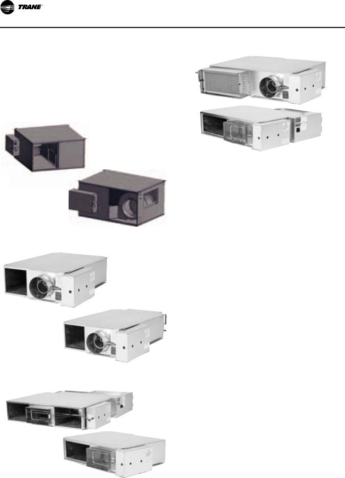
Typical Single-Duct Units
Figure 1. Typical single duct unit — VCCF
Figure 2. Typical single duct unit — VCWF
Figure 3. Typical single duct unit — VCEF
Dual-Duct Units
Dual-duct units provide two air valves: one as heating primary air and the other as cooling primary air. Both discharge into the common outlet, which leads to the zone being controlled. See Figure 4, p. 11.
Units are provided with a slip and drive rectangular duct connection or can be ordered with integral outlet plenum.
Sequencing of hot and cold air valve is dependent on job requirements. One typical control is valves working in conjunction to respond to zone temperature.
When the cooling valve becomes fully closed or reaches a specified minimum, the heating valve will begin to modulate or vice versa. The typical result is that air flowing to the zone varies from maximum down to a minimum and back up to maximum as load varies and controls would cause one air valve to close and the other to open.
Another typical application is when the unit provides a constant volume to the zone. When the zone sensor is tied directly to the heating valve, it will modulate the heating valve according to the zone temperature.
When the heating valve is fully closed or there is a call for cooling in the zone, the cooling valve will be at constant supply. As the space becomes too cool, the heating valve will modulate open, decreasing the cooling valve flow. The typical result is that the air flowing into the zone stays at a constant flow whether the unit is heating or cooling.
Figure 4. Typical dual-duct unit: VDDF
VAV-SVX08E-EN |
11 |
Unit Information
Fan-Powered and Fan-Powered Low-
Height Units
VariTrane fan-powered and low-height fan-powered units can be either parallel or series, with or without re-heat. (SeeFigure 5, p. 12 thru Figure 8, p. 12.)
Typical Fan-Powered Units
Figure 5. Parallel fan-powered terminal unit (top) & series fan-powered terminal units (bottom)
Figure 6. Low height series: LSCF (top) & low height series: LSWF (bottom)
Figure 7. Low height series: LSEF (top) & low height parallel: LPCF (bottom)
Figure 8. Low height parallel: LPWF (top) & low height parallel: LPEF (bottom)
The fan on a series unit runs continuously whenever the main air handler unit is in operation. There are various options for starting the fan. The fan can be started three ways: 1) remotely, 2) by a duct pressure switch, or 3) by a combination of both. The particular fan control method may vary from unit to unit, depending upon job needs.
Typically, heater is off while air valve modulates primary air and responds to zone temperature. If zone temperature decreases to the point where a decrease in primary air will not maintain the desired temperature, the re-heat will be activated to increase the temperature of the discharge air.
On a parallel unit, the VariTrane air valve delivers primary cooling air to the unit outlet. When the space temperature decreases beyond air valve control, the fan is turned on as the first stage of heat. The fan delivers plenum air from above the occupied space to the unit outlet, which is mixed with primary air and delivered to the occupied space.
Note: Either the fan, the air valve, or both can deliver airflow into the occupied space. In order to prevent primary airflow from exiting through the fan when the fan is not running on a parallel unit, a back draft damper is provided. When the fan is not running, the efficiency of this system is the same as a standard single-duct VAV unit.
Typically, the control systems applied to parallel units cause the air valve to close to zero or a minimum flow before the fan is activated. After the fan is activated, the optional heat will be activated upon further reduction in zone temperature. Therefore, minimal primary air is mixed with the heated air.
VariTrane fan-powered unit fan sizes 02SQ–05SQ and 08SQ–10SQ were performance tested at .12 in. w.g. and sizes 06SQ and 07SQ were tested at .15 in. w.g. Units are not designed to operate unducted and below these tested static pressures.
Note: Fan-powered units are available with rectangular discharge connection only. The optional heater is mounted on the discharge of the unit. Hot water coils are connected to either the plenum inlet or on the discharge on parallel units, and to the discharge of series units.
12 |
VAV-SVX08E-EN |
Unit Installation
 WARNING
Proper Structural Support Required!
Ceiling structure must be strong enough to support the weight of the unit. If unsure, check with a structural engineer. Refer toTable 1, p. 24 thruTable 6, p. 26 for unit weights. Failure to ensure proper structural ceiling support could result in unit failing from its location which could result in death or serious injury.
Due to their weight, the VAV terminal units should be suspended from the uppermost ceiling, independent of the false ceiling grid. Suspension devices are to be supplied by the installer. Units must be installed level and upright. Failure to level the unit properly may prevent proper operation of the controls and/or terminal unit. Units are not designed to be installed vertically. Consequently, this will also void the UL ratings and any warranty on the unit.
Single-Duct
Figure 9. Single-duct hanging recommendations
.
Depending upon the size and weight of the single-duct unit, it may be capable of being supported by the ductwork that is connected to it. No hanger brackets are provided on these units since the unit should be supported by means of a hanger strap. The hanger strap should be secured directly to the unit casing as shown in Figure 9, p. 13.
For cooling only single-duct units or single-duct units with hot water coil, the unit may be rotated 180° for opposite side connections.
For units with electric heat, the unit can be flipped to either RH or LH connection orientation if model number digit 22 Electrical Connections = F.
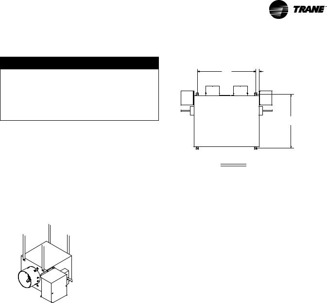
Dual-Duct
Dual-duct units should be supported by either hanger straps or by using a threaded rod in conjunction with the hanger brackets that are provided on the unit. See Figure 10, p. 13.
Figure 10. Dual-duct hanger bracket locations
B |
C |
AIR |
AIR |
VALVE |
VALVE |
COOLING |
HEATING |
A
TOP VIEW
Inlet Size |
A |
B |
C |
|
|
|
|
5" thru 10" |
23.154" (588 mm) |
25.25" (641 mm) |
1.376" (35 mm) |
|
|
|
|
12" thru 16" |
25.154" (639 mm) |
37.25" (946 mm) |
1.376" (35 mm) |
|
|
|
|
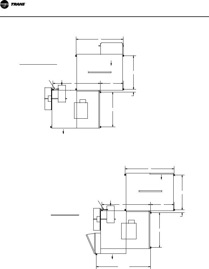
Fan-Powered (Standard and Low-Height)
Fan-powered units should be supported by either hanger straps or by using a threaded rod in conjunction with the hanger brackets that are provided on the unit. Care should be exercised to insure that the hanging straps do not block the side access panel. See Figure 11, p. 16 thru Figure 18, p. 22.
Duct Connections
All VariTrane units should be provided with a minimum of 1.5-duct diameters of straight duct prior to the inlet of the unit. It is recommended that at least 48 inches of straight duct be provided from the discharge of the units prior to any take-offs or transitions.
Important: This is a requirement for electric heat fanpowered units used in applications with 100% downward discharge.
Note: In order to maintain good air distribution over the elements and not create turbulence which could cause a limit cutout there should be four feet of ductwork, consistent of the discharge dimensions of the heater. downstream of the reheat coil prior to any diffuser takeoffs for VariTrane™ electric coils.
1.After all connections are made, check that the entire ductwork system is airtight. In some high-pressure systems, duct sealer may be necessary.
Note: All inlet duct on the VAV boxes are sized approximately 1/8" smaller in diameter than the nominal size in order to allow the incoming duct to slide over the inlet of the VAV box.
2.Provide insulation around the entire inlet collar (all the way to the unit casing).
VAV-SVX08E-EN |
13 |

Unit Installation
Note: Use caution not to damage the flow tubes when making ductwork connections or insulating.
3.Cut “slits” in the insulation for the flow tubes and secure with duct tape.
4.If the unit is to be installed in a location with high humidity, external insulation around the heating coil should be installed as required.
Water Coil Connections
Note: The following coils have 3/8” OD water coil piping connections.
•Single Duct 1-row coils (inlet sizes 05, 05, 06, 08 or 10 only)
•Low Height Parallel Inlet 1-row
•Low Height Parallel Discharge 1-row
All others require a 7/8” OD water coil piping connections.
Note:
1.If necessary, you can change the coil connection from left-handed to right-handed (and vice-versa) by disconnecting the coil from the unit and rotating the coil “like a steering wheel” 180°.
Note: Exception - Coil connection cannot be changed on parallel fan powered unit with hot water coil on plenum inlet.
2.Use port at the bottom for inlet and top for outlet on single row coils. For multirow coils, always plumb in counter flow orientation.
•Water inlet is always on the airflow downstream side of the hot water coil.
•Water outlet is always on the upstream side of the hot water coil.
3.Care should be taken to properly support the water coil piping connections while connecting the adjoining pipe.
4.It is recommended that piping to the water coil should be done after field-mounted controls, external insulation, and ductwork connections have been completed.
Important: Do not connect water valve or pipe extensions to the water coil connections unless supported.
Unit Accessibility
•Single-duct and dual-duct units provided with hot water reheat have an access panel located on the side of the water coil. All other single-duct and dual-duct units are provided without access, as all functioning components are external to the unit.
•Fan-powered terminals are provided with a sliding side access.
•Low-height terminal units have a removable bottom panel.
Clearances
For proper service, it is recommended that at least 36” of side clearance be provided to service and access singleduct and dual-duct terminals units.
•Fan-powered VAV units have a plenum inlet that must be clear of obstructions. Allow at least 36” of clearance in front of the side access and plenum opening.
•Low-height fan-powered terminals require the same plenum clearance requirement that applies to the standard fan-powered units. However the access to the internal components is located on the bottom of the unit.
It is also recommended that 6” of clearance be provided to the top and bottom of all the units.
Note: The minimum clearance for controls and heater controls should be 36” for all models except units with 575-volt electric heaters, which require 48” of clearance. NEC and/or local codes override all clearance requirements.
Actuator Mounting
Important: When installing or replacing the actuator tighten the actuator set screw per the manufacturer’s instructions. Failure to follow the manufacturer’s specifications may result in unit malfunction.
Trane offers a factory-mounted actuator with a 90-second drive time. The actuator drives 1 degree per second. A field-installed actuator may be used if desired. The actuator shaft has a ½-inch diameter and is designed to travel clockwise to close the damper and counterclockwise to open the damper. There is an indicator on the end of the actuator shaft that can be used to determine the position of the damper.
Stand Alone UCM 4.2
When there is no communication to the UCM control and the unit is in the stand alone mode the control action is determined by the auxiliary temperature sensor located on TB3-5 and TB3-6 terminals on the UCM board. In order for the auxiliary sensor to determine the control action (heat, cool) it must be located in the supply duct. The auxiliary temperature is then compared to the zone temperature. If the supply air temperature is 10 degrees above the zone temperature, then the control action will be heat. If the supply air temperature is less than or equal to the zone temperature, then the control action will be cool. If the supply air temperature is between the zone temperature and the zone temperature + 10ºF (5.5°C)(zone temperature < supply air temperature < zone temperature + 10ºF) (5.5°C), the control action remains the same and the UCM controls to the minimum flow set point. If an auxiliary sensor is not installed the UCM will retain the last control action in effect.
14 |
VAV-SVX08E-EN |

Unit Installation
Stand Alone VV550 LonTalk™ Control
When there is no communication to the VV550 control and the unit is in the stand alone mode the control action is determined by the auxiliary temperature sensor located on TB3-5 and TB3-6 terminals on the VV550 board. The control must also be configured through the “Inputs Tab” of Analog Input 4 as “Primary Supply Air Sensor”.In order for the auxiliary sensor to determine the control action (heat, cool) it must be located in the supply inlet of the duct. The auxiliary temperature is then compared to the zone temperature. If the supply air temperature is 10 degrees above the zone temperature, then the control action will be heat. If the supply air temperature is less than or equal to the zone temperature, then the control action will be cool. If the supply air temperature is between the zone temperature and the zone temperature + 10ºF (5.5°C)(zone temperature < supply air temperature < zone temperature + 10ºF) (5.5°C), the control action remains the same and the UCM controls to the minimum flow set point. If an auxiliary sensor is not installed the UCM will retain the last control action in effect.
Stand Alone UC400
When there is no communication to the UC400 control and the unit is in the stand alone mode the control action is determined by the auxiliary temperature sensor located on AI5 terminals on the UC400 control. This input may have to be changed from AI4 (Discharge Air Input) as wired from the factory. In order for the auxiliary sensor to determine the control action (heat, cool) it must be located in the supply inlet of the duct. The auxiliary temperature is then compared to the zone temperature. If the supply air temperature is 10 degrees above the zone temperature, then the control action will be heat. If the supply air temperature is less than or equal to the zone temperature, then the control action will be cool. If the supply air temperature is between the zone temperature and the zone temperature + 10ºF (5.5°C)(zone temperature < supply air temperature < zone temperature + 10ºF) (5.5°C), the control action remains the same and the UCM controls to the minimum flow set point. If an auxiliary sensor is not installed the UCM will retain the last control action in effect.
VAV-SVX08E-EN |
15 |
Unit Installation
Figure 11. Parallel hanger bracket locations sizes
|
|
C |
|
|
|
Water |
|
|
|
Coil |
|
TOP VIEW |
|
Airflow |
|
|
Plenum Inlet |
||
Parallel Cooling & Hot Water |
|||
|
|||
|
|
B |
|
Flow Ring |
Primary |
Optional Attenuator |
|
Airflow |
Field Installed |
||
Tubing |
|||
F |
E |
||
|
|||
|
Air |
|
|
|
Valve |
|
|
|
|
D |
|
|
|
A |
|
|
Airflow |
|
|
|
Discharge Outlet |
|
|
FAN SIZE |
A |
B |
C |
D |
E |
F |
02SQ |
26.75" (679 mm) |
26.75" (679 mm) |
41.154" (1041 mm) |
3.25" (83 mm) |
20.00" (508 mm) |
38.95" (989 mm) |
03SQ, 04SQ, 05SQ |
29.75" (756 mm) |
26.75" (679 mm) |
41.154" (1041 mm) |
3.25" (83 mm) |
20.00" (508 mm) |
38.95" (989 mm) |
06SQ, 07SQ |
36.75" (933 mm) |
26.75" (679 mm) |
41.154" (1041 mm) |
3.25" (83 mm) |
20.00" (508 mm) |
38.95" (989 mm) |
TOP VIEW
Parallel Electric Heat
|
|
C |
|
|
|
Airflow |
|
|
|
Plenum Inlet |
|
|
Primary |
Optional Attenuator |
B |
|
|
||
Flow Ring |
Field Installed |
|
|
Airflow |
|
||
|
|
||
Tubing |
F |
E |
|
|
|
||
|
Air |
|
|
|
Valve |
|
|
|
|
|
D |
|
|
A |
|
Terminal Box |
Heater |
|
|
|
|
|
|
|
Airflow |
|
|
|
Discharge Outlet |
|
|
|
43.546 |
|
|
|
(1106 mm) |
|
|
16 |
VAV-SVX08E-EN |
Unit Installation
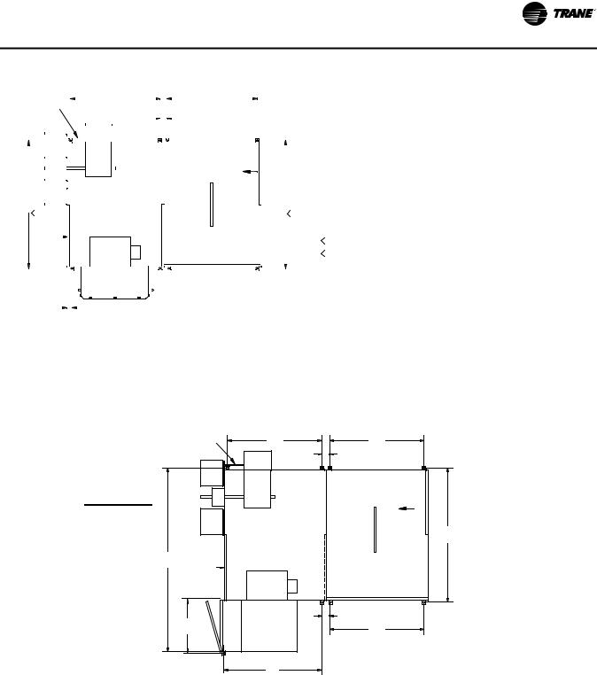
Figure 12. Series hanger bracket locations
|
|
Flow Ring |
|
|
|
|
|
|
|
|
|
|
|
|
|
|
|
|
|
|
|
|
|
|
|
|
|
|
|
|
|
|
|
|
|
|
|
|
|
|
|
|
|
||||
|
|
|
Tubing |
|
|
|
|
|
|
|
|
|
|
|
|
|
|
|
|
|
|
C |
|
|
|
|
|
|
|
|
|
|
|
|
|
|
|
|
|
|
|
|
|
|
|||
|
|
|
|
|
|
|
|
|
|
|
|
|
|
|
|
|
|
|
|
|
|
|
|
|
|
|
|
|
|
|
|
|
|
|
|
|
|
|
|
|
|
|
|
|
|
|
|
|
|
|
|
|
|
|
|
|
|
|
|
|
|
|
|
|
|
|
|
|
|
|
|
|
|
|
|
|
|
|
|
|
|
|
|
|
|
|
|
|
|
|
|
|
|
|
|
|
|
|
|
|
|
|
|
|
Air |
|
|
|
|
|
|
|
|
|
|
|
|
|
|
|
|
|
|
|
|
|
|
|
|
|
|
|
|
|
|
|
|
|
|
|
|
|
|
|
|
|
|
|
|
|
|
|
Valve |
|
|
|
|
|
|
|
|
|
|
|
|
|
|
|
|
|
|
|
|
|
|
|
|
|
|
|
|
|
|
|
|
|
|
|
|
||
|
|
|
|
|
|
|
|
|
|
|
|
|
|
|
|
|
|
|
|
|
|
|
|
|
|
|
|
|
|
|
|
|
|
|
|
|
|
|
|
|
|
|
|
|
|
|
|
|
|
|
|
|
|
|
|
|
|
|
|
|
|
|
|
|
|
|
|
|
|
|
|
|
Optional Attenuator |
|
|
|
|
|
|
|
|
|
|
|
|
|
|
|
|||||||
|
|
|
|
|
|
|
|
|
|
|
|
|
|
|
|
|
|
|
|
|
|
|
|
|
|
Field Installed |
|
|
|
|
|
|
|
|
|
|
|
|
|
|
|
||||||
|
|
|
|
|
|
|
|
|
|
|
|
|
|
|
|
|
|
|
|
|
|
|
|
|
|
|
|
|
|
|
|
|
|
|
|
|
|
|
|
|
|||||||
|
|
|
|
|
|
|
|
|
|
|
|
|
|
|
|
|
|
|
|
|
|
|
|
|
|
|
|
Airflow |
|
|
|
|
|
|
|
|
|
|
|
|
TOP VIEW |
|
|
|
|
||
|
|
|
|
|
|
|
|
|
|
|
|
|
|
|
|
|
|
|
|
|
|
|
|
|
|
|
|
|
|
|
|
|
|
|
|
|
|
|
|||||||||
|
|
|
|
|
|
|
|
|
|
|
|
|
|
|
|
|
|
|
|
|
|
|
|
|
|
|
|
|
|
|
|
|
|
|
|
|
|
|
|||||||||
|
|
|
|
|
|
|
|
|
|
|
|
|
|
|
|
|
|
|
|
|
|
|
|
|
|
|
|
Plenum Inlet |
|
|
|
|
|
|
|
|
|
|
|
|
|
||||||
|
|
|
|
|
|
|
|
|
|
|
|
|
|
|
|
|
|
|
|
|
|
|
|
|
|
|
|
|
|
|
|
|
|
|
Series Cooling & Hot Water |
|
|
|
|
||||||||
|
|
|
|
|
|
|
|
|
|
|
|
|
|
|
|
|
|
|
|
|
|
|
|
|
|
|
|
|
|
|
|
|
|
|
|
|
|||||||||||
|
|
|
|
|
|
|
|
|
|
|
|
|
|
|
|
|
|
|
|
|
|
|
|
|
|
|
|
|
|
|
|
|
|
|
|
|
|
|
|
|
|
|
|
||||
|
|
|
|
|
|
|
|
|
|
|
|
|
|
|
|
|
|
|
|
|
|
|
|
|
|
|
|
|
|
|
|
|
|
|
|
|
|
|
|
|
|
|
|
|
|
|
|
|
|
|
|
|
|
|
|
|
|
|
|
|
|
|
|
|
|
|
|
|
|
|
|
|
|
|
|
|
|
|
|
|
|
|
|
|
|
|
|
|
|
|
|
|
|
|
|
|
E |
|
|
|
|
|
|
|
|
|
|
|
|
|
|
|
|
|
|
|
|
|
|
|
|
|
|
|
|
|
|
|
|
|
|
|
|
|
|
|
|
|
|
|
|||
|
|
|
|
|
|
|
|
|
|
|
|
|
|
|
|
|
|
|
|
|
|
|
|
|
|
|
|
|
|
|
D |
|
|
|
|
|
|
||||||||||
|
|
|
|
|
|
|
|
|
|
|
|
|
|
|
|
|
|
|
|
|
|
|
|
|
|
|
|
|
|
|
|
|
|
|
|
|
|||||||||||
|
|
2. |
|
|
|
|
|
|
|
|
|
|
|
|
|
|
|
|
|
|
|
|
|
|
|
|
|
|
|
|
|
|
|
|
|
|
|
|
|
|
|
|
|
|
|
||
|
|
|
|
|
|
|
|
|
|
|
|
|
|
|
|
|
|
|
|
|
|
|
|
|
|
|
|
|
|
|
|
|
|
|
1. |
|
|
|
|
|
|
|
|
||||
Fan Inlet w/o |
|
|
|
|
|
|
|
|
|
|
|
|
|
|
|
|
|
|
|
|
|
|
|
|
|
|
|
|
|
|
|
|
|
|
|
|
|
|
|
|
|
||||||
|
Attenuator |
|
|
|
|
|
|
|
|
|
|
|
|
|
|
|
|
|
|
|
|
|
|
|
|
|
|
|
|
|
|
|
|
|
|
|
|
1. |
All attenuators are the same length and width. |
|
|||||||
|
|
|
|
|
|
|
|
|
|
|
|
|
|
|
|
|
|
|
|
|
|
|
|
|
|
|
|
|
|
|
|
|
|
|
|
|
|
|
|
|
|
|
Sizes 01 and 02 units are smaller than attenuators. |
|
|||
|
|
|
|
|
|
|
|
|
|
|
|
|
|
|
|
|
|
|
|
|
|
|
|
|
|
|
|
|
|
|
|
|
|
|
|
|
|
|
|
|
|
2. |
|
||||
|
|
|
|
|
|
|
|
|
|
|
|
|
|
|
|
|
|
|
|
|
|
|
|
|
|
|
|
|
|
|
|
|
|
|
|
|
|
|
|
|
|
|
|
|
|
|
|
|
|
|
|
|
|
|
|
|
|
|
|
|
|
|
|
|
|
|
|
|
|
|
|
|
|
|
|
|
|
|
|
|
|
|
|
|
|
|
|
|
|
|
|
|
|
|
|
|
|
|
|
|
|
|
|
|
Water |
|
|
|
|
|
|
|
|
|
|
|
|
|
|
|
|
|
|
|
|
|
|
|
|
|
|
|
|
|
|
|
|
|
|
|
|||
1.625" |
|
|
|
Coil |
|
|
|
|
|
|
|
|
|
|
|
|
|
|
|
|
|
|
|
|
|
|
|
|
|
|
|
|
|
|
|
|
|
|
|
||||||||
|
|
|
|
|
|
|
|
|
|
|
|
|
|
|
|
|
|
|
|
|
|
|
|
|
|
|
|
|
|
|
|
|
|
|
|
|
|
||||||||||
|
|
|
|
|
|
|
|
|
|
|
|
|
|
|
|
|
|
|
|
|
|
|
|
|
|
|
|
|
|
|
|
|
|
|
|
|
|
|
|
|
|
||||||
|
|
|
|
|
|
|
|
|
|
|
|
|
|
|
|
|
|
|
|
|
|
|
|
|
|
|
|
|
|
|
|
|
|
|
|
|
|
|
|
|
|
|
|
|
|
|
|
|
|
(41 mm) |
|
|
|
|
|
|
|
|
|
|
|
|
|
|
|
|
|
|
|
|
|
|
|
|
|
|
|
|
|
|
|
|
|
|
|
|
|
|
|
|
|
|
|||
|
|
|
|
|
|
|
|
|
|
|
|
|
|
|
|
|
|
|
|
|
|
|
|
|
|
|
|
|
|
|
|
|
|
|
|
|
|
|
|
|
|||||||
|
|
|
|
|
|
|
|
|
|
|
|
|
|
|
|
|
|
|
|
|
|
|
|
|
|
|
|
|
|
|
|
|
|
|
|
|
|
|
|
|
|
|
|
|
|
|
|
FAN SIZE |
|
|
|
A |
|
|
|
B |
|
|
C |
|
|
|
|
|
D |
|
E |
|
F |
G |
J |
||||||||||||||||||||||||
|
|
|
|
|
|
|
|
|
|
|
|
|
|
(Elec. Heat Only) |
(Elec. Heat Only) |
(Elec. Heat Only) |
|||||||||||||||||||||||||||||||
|
|
|
|
|
|
|
|
|
|
|
|
|
|
|
|
|
|
|
|
|
|
|
|
|
|
|
|
|
|
|
|
|
|
|
|
|
|
|
|
|
|
|
|
|
|||
|
02SQ |
|
18.75" (476 mm) |
26.75" (679 mm) |
|
3.25" (83 mm) |
|
41.154" (1041 mm) |
35.154 (740 mm) |
|
20.132" (511 mm) |
53.750" (1365 mm) |
19.00" (483 mm) |
||||||||||||||||||||||||||||||||||
|
|
|
|
|
|
|
|
|
|
|
|
|
|
|
|
|
|
|
|
||||||||||||||||||||||||||||
03SQ, 04SQ |
|
20.75" (527 mm) |
26.75" (679 mm) |
|
3.25" (83 mm) |
|
41.154" (1041 mm) |
41.154" (1041 mm) |
|
23.875 (606 mm) |
59.750” (1517 mm) |
19.00" (483 mm) |
|||||||||||||||||||||||||||||||||||
|
|
|
|
|
|
|
|
|
|
|
|
|
|
|
|
|
|
|
|
|
|
|
|
|
|
|
|
|
|
|
|
|
|
|
|
||||||||||||
05SQ |
|
26.75" (679 mm) |
26.75" (679 mm) |
|
3.25" (83 mm) |
|
|
41.154" (1041 mm) |
41.154" (1041 mm) |
|
28.966" (736 mm) |
59.750" (1517 mm) |
19.00" (483 mm) |
||||||||||||||||||||||||||||||||||
|
|
|
|
|
|
|
|
|
|
|
|
|
|
|
|
|
|
|
|
|
|
|
|
|
|||||||||||||||||||||||
|
|
|
|
|
|
|
|
|
|
|
|
|
|
|
|
|
|
|
|
||||||||||||||||||||||||||||
06SQ, 07SQ |
|
27.25" (692 mm) |
26.75" (679 mm) |
|
3.25" (83 mm) |
|
|
41.154" (1041 mm) |
41.154" (1041 mm) |
|
29.875" (759 mm) |
58.250" (1479 mm) |
17.50" (445 mm) |
||||||||||||||||||||||||||||||||||
|
|
|
|
|
|
|
|
|
|
|
|
|
|
|
|
|
|
|
|
|
|
|
|
|
|
|
|
|
|
|
|
|
|
|
|
|
|
|
|
|
|
|
|
|
|
|
|
TOP VIEW
Series Electric Heat
|
Flow Ring |
A |
B |
|
Tubing |
||
|
|
C |
|
|
|
Air |
|
|
|
|
|
|
|
Valve |
|
|
|
|
Optional Attenuator |
|
|
|
Field Installed |
|
|
|
Airflow |
|
|
|
Plenum Inlet |
|
|
|
D |
G |
Fan Inlet w/o |
|
|
|
Attenuator |
|
|
|
|
Electric |
|
|
|
Heater |
C |
|
J |
|
B |
|
|
|
|
|
|
F |
|
VAV-SVX08E-EN |
17 |
Loading...