


Installation/
Operator
Maintenance
VariTrane™ Single-Duct
and Fan-Powered Units
AllVariTraneVAV Models with pneumatic, electronic, DDC controls and diffusers.
June 2006 |
VAV-SVN01E-EN |

|
|
|
|
|
|
|
|
© 2006 American Standard All rights reserved |
VAV-SVN01E-EN |
||

Contents
Service Model Number Description .................. |
4 – 14 |
General Information ............................................... |
15 |
Literature Contents |
|
Receiving and Handling |
|
Warnings and Cautions Explanations |
|
Unit Information ............................................. |
16 – 17 |
Single-Duct Units |
|
Dual-Duct Units |
|
Fan-Powered and Low-Height Units |
|
Unit Installation .............................................. |
18 – 31 |
Hanging Bracket Locations |
|
Unit Weights |
|
Water Coil Connections |
|
Unit Accessibility |
|
Clearances |
|
Actuator Mounting |
|
Unit Setup ...................................................... |
32 – 46 |
Flow Sensor ∆P vs. Airflow Delivery |
|
Maximum Fan Motor Amperage |
|
(SCR) Motor Speed Control Adjustment Procedure |
|
Electrically Commutated Motor (ECM) |
|
ECM CFMTables |
|
Wiring Diagrams ............................................. |
47 – 54 |
Maintenance .......................................................... |
55 |
Motors |
|
FanWheel |
|
Filter |
|
Water Coil |
|
Fan Motor Replacement |
|
Installation of Diffusers .......................................... |
56 |
T-Bar Ceiling |
|
Concealed Spline Ceiling |
|
Drywall/Plaster Ceiling |
|
VAV-SVN01E-EN |
3 |
Service Model
Number Description
WARNING
Fiberglass Wool!
WARNING: ALL INSULATED UNITS (except closed-cell foam insulation) CONTAIN FIBERGLASSWOOL! Read this literature prior to installation for proper instruction. Disturbing the insulation in this product during installation, maintenance or repair will expose you to airborne particles of glass wool fibers and ceramic fibers known to the state of California to cause cancer through inhalation. Glass wool fibers may also cause respiratory, skin or eye irritation.
Single-Duct Units
Digit 1, 2—UnitType
VC |
VariTrane single-duct |
Digit 3—Reheat
C Cooling Only
E Electric Heat W HotWater Heat
Digit 4—Development Sequence
F Sixth
Digit 5, 6—PrimaryAirValve
04 4" inlet (225 cfm)
05 5" inlet (350 cfm)
06 6" inlet (500 cfm)
08 8" inlet (900 cfm)
10 10" inlet (1400 cfm)
12 12" inlet (2000 cfm)
14 14" inlet (3000 cfm)
16 16" inlet (4000 cfm)
24 24" x 16" inlet (8000 cfm)
Digit 7, 8—Not Used
00 N/A
Digit 9—Not Used
0 N/A
Digit 10, 11—Design Sequence
H0 Fourth (factory assigned)
Digit 12, 13, 14, 15—Controls
ENON No controls, field-installed DDC/electric
PNON No controls, field-installed pneumatic
DD00 Trane elec actuator only DD01 DDC – Cooling only
DD02 DDC – N.C. on/off water valve control
DD03 DDC – Prop hot water valve control
DD04 DDC – On/off electric heat DD05 DDC – Pulse-width modulation
electric heat
DD07 DDC – N.O. on/off water valve control
DD11 LonTalk DDC Controller— Cooling only
DD12 LonTalk DDC Controller w/ N.C. on/off hot water control
DD13 LonTalk DDC Controller w/ proportional hot water control
DD14 LonTalk DDC Controller–on/off electric heat control
DD15 LonTalk DDC Controller w/ pulse-width modulation electric heat control
DD17 LonTalk DDC Controller w/ N.O. on/off hot water control
FM00 FM – Customer-supplied actuator & controller
FM01 FM –Trane actuator w/ cusomersupplied control
VMA1 FM – Johnson controlsVMA-1410 VMA2 FM – Johnson controlsVMA-1420 PWR1 FM – Seimens 540-100 w/
GDE131.1P actuator
PWR4 FM – Seimens 540-100 w/Trane actuator
PWR5 FM – Seimens 540-100 w/ GDE131.1U actuator
AT01 FM – Automated Logic U341V+ AT02 FM – Automated Logic U141V+ EI05 Analog –With optional on/off
reheat
EI28 Analog –With optional on/off reheat with dual-minimum cfm
EI29 Analog –With optional on/off reheat with constant-volume cfm
PC00 PN – N.C.Trane pneumatic actuator
PC04 PN – N.C. with optional on/off HW, DA Stat
PC05 PN – N.C. with optional on/off electric, RA Stat
PN00 PN – N.O.Trane pneumatic actuator, RA Stat
PN04 PN – N.O. PVR, DA Stat
PN05 PN – N.O. PVR, RA Stat
PN11 PN – N.O. dual-minimum cfm, DA Stat
PN32 PN –WaterValve, N.O. constant volume, DA Stat
PN34 PN – Electric heat, N.O. constant volume, DA Stat
Notes:
N.C. = Normally-closed
N.O. = Normally-opened
DA Stat = Direct-acting pneumatic t-stat (by others)
RA Stat = Reverse-acting pneumatic t-stat (by others)
PN = Pneumatic
FM = Factory installation of customersupplied controller
PVR = PneumaticVolume Regulator
Digit 16—Insulation
A1/2" Matte-faced
B1" Matte-faced
C1/2" Foil-faced
D1" Foil-faced
F1" Double-wall
G3/8" Closed-cell
4 |
VAV-SVN01E-EN |
Service Model
Number Description
Single-Duct Units (con't.)
Digit 17—Not Used
0 N/A
Digit 18—Not Used
0 N/A
Digit 19—Outlet Plenum (Connection is Slip & Drive)
0 None
A1 Outlet RH
B1 Outlet END
C1 Outlet LH
D2 Outlets, 1 RH, 1 END
E2 Outlets, 1 LH, 1 END
F2 Outlets, 1 RH, 1 LH
H 3 Outlets, 1 LH, 1 RH, 1 END J 4 Outlets, 1 LH, 1 RH, 2 END
Note: See unit drawings for outlet sizes/ damper information.
Digit 20—Not Used
0 N/A
Digit 21—Water Coil
0None
11-Row
22-Row
Digit 22—Electrical Connections (VCCF, VCWF can be flipped in the field to achieve opposite-hand connection)
L Left (Airflow hitting you in the face)
R Right (Airflow hitting you in the face)
0Opposite side connection – coil and control
Digit 23—Transformer
0None
1120/24 volt (50VA)
2208/24 volt (50VA)
3240/24 volt (50VA)
4277/24 volt (50VA)
5480/24 volt (50VA)
6347/24Volt (50VA)
7575/24Volt (50VA)
8380/24Volt (50VA)
Note: ForVCEF units with transformers theVA depends on the staging, control, and contactor type (ranges are 40VA to 75VA)
Digit 24—Disconnect Switch
0 |
None |
W |
With |
|
|
Note: |
VCCF,VCWF –Toggle Disconnect |
|
VCEF – Door Interlocking Power |
|
Disconnect |
Digit 25—Power Fuse
0 |
None |
W |
With |
Digit 26—Electric HeatVoltage
0 None
A208/60/1
B208/60/3
C240/60/1
D277/60/1
E480/60/1
F480/60/3
G347/60/1
H575/60/3
J380/50/3
K120/60/1
Digit 27, 28, 29—Electric Heat kW
000 |
None |
||
050 |
0.5 kW |
||
010 |
1.0 kW |
||
015 |
1.5 kW |
||
|
|
|
|
|
|
|
|
460 |
46.0 kW |
||
Notes:
0.5 to 8.0 kW – ½ kW increments
8.0 to 18.0 kW – 1 kW increments
18.0 to 46.0 kW – 2 kW increments
Digit 30—Electric Heat Stages
0None
11 Stage
22 Stages Equal
33 Stages Equal
Digit 31—Contactors
0None
124-volt magnetic
224-volt mercury
3PE with magnetic
4PE with mercury
Digit 32—Not Used
0 N/A
VAV-SVN01E-EN |
5 |
Dual-Duct Units
Digit 1, 2, 3—UnitType
VDD VariTrane dual-duct
Digit 4—Development Sequence
F Sixth
Digit 5, 6—PrimaryAirValve
05 5" inlet (350 cfm)
06 6" inlet (500 cfm)
08 6" inlet (900 cfm)
10 10" inlet (1400 cfm)
12 12" inlet (2000 cfm)
14 14" inlet (3000 cfm)
16 16" inlet (4000 cfm)
Digit 7, 8—SecondaryAirValve
05 5" inlet (350 cfm)
06 6" inlet (500 cfm)
08 8" inlet (900 cfm)
10 10" inlet (1400 cfm)
12 12" inlet (2000 cfm)
14 14" inlet (3000 cfm)
16 16" inlet (4000 cfm)
Digit 9—Not Used
0 N/A
Digit 10, 11—Design Sequence
C0 Third (factory assigned)
Digit 12, 13, 14, 15—Controls
ENON No Controls, Field-installed DDC/Electric
PNON No Controls, Field-installed Pneumatic
DD00 Trane elec actuator only DD01 DDC – Cooling only DD08 DDC – Constant-volume
discharge
DD11 LonTalk DDC Controller— Cooling only
DD18 LonTalk DDC Controller— ConstantVolume Discharge
Service Model
Number Description
FM00 FM – Customer-supplied actuator & controller
FM01 FM –Trane actuator w/ customer-supplied controller
PC03 PN – N.C. heating/ N.O. cooling w/ PVRs, DA stat
PN08 PN – N.O. heating/ N.O. cool act. only, RA stat
PN09 PN – N.O. htg/clg vlvs w/ PVRs, DA stat
PN10 PN – N.O. htg/clg w/ PVRs (cv disch), DA stat.
Notes:
N.C. = Normally-closed
N.O. = Normally-opened
DA Stat = Direct-acting pneumatic t-stat (by others)
RA Stat = Reverse-acting pneumatic t-stat (by others)
PN = Pneumatic
FM = Factory installation of customersupplied controller
PVR = PneumaticVolume Regulator
Digit 16—Insulation
A1/2" Matte-faced
B1" Matte-faced
C1/2" Foil-faced
D1" Foil-faced
F1" Double-wall
G3/8" Closed-cell
Digit 17—Not Used
0 N/A
Digit 18—Not Used
0 N/A
Digit 19—Outlet Plenum (Connection is slip & drive)
0 none
A1 outlet–RH
B1 outlet–END
C1 outlet–LH
D2 outlets–1 RH, 1 END
E2 outlets–1 LH, 1 END
F2 outlets–1 RH, 1 LH
G2 outlets - END
H3 outlets–1 LH, 1 RH, 1 END
J4 outlets–1 LH, 1 RH, 2 END
Note: See unit drawings for outlet sizes/ damper information.
Digit 20—Not Used
0 N/A
Digit 21—Not Used
0 N/A
Digit 22—Not Used
0 N/A
Digit 23—Transformer
0None
1120/24 volt (50VA)
2208/24 volt (50VA)
3240/24 volt (50VA)
4277/24 volt (50VA)
5480/24 volt (50VA)
6347/24 volt (50VA)
7575/24 volt (50VA)
Digit 24—Disconnect Switch
0 |
None |
W |
WithToggle |
Digit 25—Power Fuse
0 |
None |
W |
With |
6 |
VAV-SVN01E-EN |
Service Model
Number Description
Fan-Powered Parallel Units
Digit 1, 2—UnitType
VP |
VariTrane fan-powered parallel |
Digit 3—Reheat
C Cooling Only
E Electric Heat W HotWater Heat
Digit 4—Development Sequence
F Sixth
Digit 5, 6—PrimaryAirValve
05 5" inlet (350 max cfm)
06 6" inlet (500 max cfm)
08 8" inlet (900 max cfm)
10 10" inlet (1400 max cfm)
12 12" inlet (2000 max cfm)
14 14" inlet (3000 max cfm)
16 16" inlet (4000 max cfm)
Digit 7, 8—SecondaryAirValve
00 N/A
Digit 9—Fan
P02SQ fan (500 nominal cfm)
Q03SQ fan (1100 nominal cfm)
R04SQ fan (1350 nominal cfm)
S05SQ fan (1550 nominal cfm)
T06SQ fan (1850 nominal cfm)
U07SQ fan (2000 nominal cfm)
Digit 10, 11—Design Sequence
J0 Design Sequence (Factory assigned)
Digit 12, 13, 14, 15—Controls
ENON No controls, field-installed DDC or analog
ENCL ENON with controls enclosure PNON No controls, field-installed pneumatic
DD00 Trane elec actuator only DD01 DDC – cooling only
DD02 DDC – N.C. on/off water control DD03 DDC – prop hot water control DD04 DDC – on/off electric heat control
DD05 DDC – pulse-width modulation electric heat control
DD07 DDC – N.O. on/off hot water control
DD11 LonTalk DDC Controller— Cooling only
DD12 LonTalk DDC Controller w/ N.C. on/off hot water control
DD13 LonTalk DDC Controller w/ proportional hot water control DD14 LonTalk DDC Control–on/off electric heat control
DD15 LonTalk DDC Controller w/ pulse-width modulation electric heat control
DD17 LonTalk DDC Controller w/ N.O. on/off hot water control
FM00 FM customer actuator & control FM01 FMTrane actuator w/ customersupplied controller
VMA2 FM Johnson Controls VMA-1420
PWR1 FM Seimens 540-100 w/ GDE131.1P actuator
PWR4 FM Seimens 540-100 w/Trane actuator
PWR5 FM Seimens 540-100 w/ GDE131.1U actuator
AT01 FM Automated Logic U341V+ AT02 FM Automated Logic U141V+ EI05 Analog – fan-powered parallel with optional on/off reheat
PN00 PN – N.O.Trane pneumatic actuator, R.A. stat
PN05 PN – N.O. PVR, R.A. stat
Notes:
N.C. = Normally-closed
N.O = Normally-opened
DA Stat = Direct-acting pneumatic t-stat (by others)
RA Stat = Reverse-acting pneumatic t-stat (by others)
PN = Pneumatic
FM = Factory installation of customersupplied controller
PVR = PneumaticVolume Regulator
Digit 16—Insulation
A1/2" Matte-faced
B1" Matte-faced
C1/2" Foil-faced
D1" Foil-faced
F1" Double-wall
G3/8" Closed-cell
Digit 17—MotorType
DPSC Motor
EHigh-efficiency motor (ECM)
Digit 18—MotorVoltage
1115/60/1
2277/60/1
3347/60/1
4208/60/1
5230/50/1
Digit 19—Outlet Connection
1Flanged
2Slip & Drive
Digit 20—Attenuator
0 |
None |
W |
With |
Digit 21—Water Coil
0None
11-Row–Plenum inlet installed RH
22-Row–Plenum inlet installed RH
31-Row–Discharge installed, LH
41-Row–Discharge installed, RH
52-Row–Discharge installed, LH
62-Row–Discharge installed, RH
Digit 22—Electrical Connections
L |
Left |
R |
Right |
Electrical Connections Note:Airflow hitting you in the face.
Digit 23—Transformer
0 |
N/A (provided as standard) |
Digit 24—Disconnect Switch |
|
0 |
None |
W |
With |
|
|
Note: |
VPCF,VPWF –Toggle Disconnect |
|
VPEF – Door Interlocking Power |
|
Disconnect |
Digit 25—Power Fuse
0 |
None |
W |
With |
Digit 26—Electric HeatVoltage
0 None
A208/60/1
B208/60/3
C240/60/1
D277/60/1
E480/60/1
F480/60/3
G347/60/1
H575/60/3
J380/50/3
K120/60/1
Digit 27, 28, 29—Electric HeatVoltage
000 |
None |
050 |
0.5 kW |
010 |
1.0 kW |
015 |
1.5 kW |
260 26.0 kW
Electric HeatVoltage Notes: 0.5 to 8.0 kW–½ kW increments
8.0 to 18.0 kW –1 kW increments
18.0 to 46.0 kW–2 kW increments
VAV-SVN01E-EN |
7 |

Service Model
Number Description
Fan-Powered Parallel Units (con't)
Digit 30—Electric Heat Stages
0None
11 Stage
22 Stages Equal
33 Stages Equal
Digit 31—Contactors
0None
124-volt magnetic
224-volt mercury
3PE with magnetic
4PE with mercury
Digit 32—Airflow Switch
0 |
None |
W |
With |
8 |
VAV-SVN01E-EN |
Service Model
Number Description
Fan-Powered Series Units
Digit 1, 2—UnitType
VS |
VariTrane fan-powered series |
Digit 3—Reheat
C Cooling Only
E Electric Heat W HotWater Heat
Digit 4—Development Sequence
F Sixth
Digit 5, 6—PrimaryAirValve
04 4" inlet (225 max cfm)
05 5" inlet (350 max cfm)
06 6" inlet (500 max cfm)
08 8" inlet (900 max cfm)
10 10" inlet (1400 max cfm)
12 12" inlet (2000 max cfm)
14 14" inlet (3000 max cfm)
16 16" inlet (4000 max cfm)
Digit 7, 8—SecondaryAirValve
00 N/A
Digit 9—Fan
P02SQ fan (700 nominal cfm)
Q03SQ fan (1200 nominal cfm)
R04SQ fan (1550 nominal cfm)
S05SQ fan (1900 nominal cfm)
T06SQ fan (2600 nominal cfm)
U07SQ fan (3000 nominal cfm)
Fan Note: See fan curves for specific airflows
Digit 10, 11—Design Sequence
J0 Design Sequence (Factory assigned)
Digit 12, 13, 14, 15—Controls
ENON No controls, field-installed DDC or analog
ENCL ENON with control enclosure PNON No controls, field-installed
pneumatic
DD00 Trane elec actuator only DD01 DDC – cooling only
DD02 DDC – N.C. on/off water control DD03 DDC – prop hot water control DD04 DDC – on/off electric heat
control
DD05 DDC – pulse-width modulation electric heat control
DD07 DDC N.O. on/off hot water control
DD11 LonTalk DDC Controller— Cooling only
DD12 LonTalk DDC Controller w/ N.C. on/off hot water control
DD13 LonTalk DDC Controller w/ proportional hot water control
DD14 LonTalk DDC Controller–on/off electric heat control
DD15 LonTalk DDC Controller w/ pulse-width modulation electric heat control
DD17 LonTalk DDC Controller w/ N.O. on/off hot water control
FM00 FM customer actuator & control FM01 FMTrane actuator w/ customer-
supplied controller
VMA2 FM Johnson controlsVMA-1420 PWR1 FM Seimens 540-100 w/
GDE131.1P actuator
PWR4 FM Seimens 540-100 w/Trane actuator
PWR5 FM Seimens 540-100 w/ GDE131.1U actuator
AT01 FM Automated Logic U341V+ AT02 FM Automated Logic U141V+ EI71 Analog fan-powered series
with optional on/off reheat PN00 PN – N.O.Trane pneumatic
actuator, R.A. stat
PN51 PN – N.O. PVR, duct pressure switch, R.A. stat
PN52 PN – N.O. PVR, dual pressure main, R.A. stat
Notes:
N.C. = Normally-closed
N.O. = Normally-opened
DA Stat = Direct-acting pneumatic t-stat (by others)
RA Stat = Reverse-acting pneumatic t-stat (by others)
PN = Pneumatic
FM = Factory installation of customersupplied controller
PVR = PneumaticVolume Regulator
Digit 16—Insulation
A1/2" Matte-faced
B1" Matte-faced
C1/2" Foil-faced
D1" Foil-faced
F1" Double-wall
G3/8" Closed-cell
Digit 17—MotorType
DPSC Motor
EHigh-efficiency motor (ECM)
Digit 18—MotorVoltage
1115/60/1
2277/60/1
3347/60/1
4208/60/1
5230/50/1
Digit 19—Outlet Connection
1Flanged
2Slip & Drive
Digit 20—Attenuator
0 |
None |
W |
With |
Digit 21—Water Coil
0 None
31-Row–Discharge installed, LH
41-Row–Discharge installed, RH
52-Row–Discharge installed, LH
62-Row–Discharge installed, RH
Digit 22—Electrical Connections
L |
Left |
R |
Right |
Water Coil and Electrical Connections Note:Airflow hitting you in the face.
Digit 23—Transformer
0 |
N/A (provided as standard) |
Digit 24—Disconnect Switch |
|
0 |
None |
W |
With |
|
|
Note: |
VSCF,VSWF –Toggle Disconnect |
|
VSEF – Door Interlocking Power |
|
Disconnect |
Digit 25—Power Fuse
0 |
None |
W |
With |
Digit 26—Electric HeatVoltage
0 None
A208/60/1
B208/60/3
C240/60/1
D277/60/1
E480/60/1
F480/60/3
G347/60/1
H575/60/3
J380/50/3
K120/60/1
VAV-SVN01E-EN |
9 |
Service Model
Number Description
Fan-Powered Series Units (con't)
Digit 27, 28, 29—Electric Heat Kilowatts
000 |
None |
050 |
0.5 kW |
010 |
1.0 kW |
015 |
1.5 kW |
240 24.0 kW
Digit 30—Electric Heat Stages
0None
11 Stage
22 Stages Equal
33 Stages Equal
Digit 31—Contactors
0None
124-volt magnetic
224-volt mercury
3PE with magnetic
4PE with mercury
Digit 32—Airflow Switch
0 |
None |
W |
With |
10 |
VAV-SVN01E-EN |
Service Model
Number Description
Fan-Powered Low-Height Parallel Units
Digit 1, 2—UnitType
LP |
VariTrane fan-powered low- |
|
height parallel |
Digit 3—Reheat
C Cooling Only
E Electric Heat W HotWater Heat
Digit 4—Development Sequence
F Sixth
Digit 5, 6—PrimaryAirValve
05 |
5" inlet (350 maximum cfm) |
06 |
6" inlet (500 maximum cfm) |
08 |
8" inlet (900 maximum cfm) |
RT |
8" x 14" inlet (1800 maximum cfm) |
Digit 7, 8—Secondary AirValve
00 N/A
Digit 9—Fan
V08SQ 500 nominal cfm
W09SQ 900 nominal cfm
X10SQ 1800 nominal cfm
Digit 10, 11—Design Sequence
K0 Sixth (factory assigned)
Digit 12, 13, 14, 15—Controls
ENON No controls, field-installed DDC/ electric
PNON No controls, field-installed pneumatic
DD00 Trane elec actuator only DD01 DDC – cooling only
DD02 DDC – N.C. on/off water valve control
DD03 DDC – prop hot water valve control
DD04 DDC – on/off electric heat control DD05 DDC – pulse-width modulation
control
DD07 DDC – N.O. on/off water valve control
DD11 LonTalk DDC Controller—Cooling only
DD12 LonTalk DDC Controller w/ N.C. on/off hot water control
DD13 LonTalk DDC Controller w/ proportional hot water control
DD14 |
LonTalk DDC Controller–on/off |
|
|
electric heat control |
|
DD15 LonTalk DDC Controller w/ |
||
pulse- |
|
width modulation |
electric heat |
control |
|
DD17 LonTalk DDC Controller w/ N.O. on/off hot water control
FM00 FM customer actuator & control FM01 FMTrane actuator w/ customer-
supplied controller
VMA2 FM Johnson ControlsVMA1420
PWR1 FM Seimens 540-100 w/ GDE131.1P actuator
PWR4 FM Seimens 540-100 w/Trane actuator
PWR5 FM Seimens 540-100 w/ GDE131.1U actuator
AT01 FM Automated Logic U341V+ AT02 FM Automated Logic U141V+ EI05 Analog – fan-powered parallel
with optional on/off reheat PN00 PN – N.O.Trane pneumatic
actuator, R.A. stat PN05 PN – N.O. PVR, R.A. stat
Notes:
N.C. = Normally-closed
N.O. = Normally-opened
DA Stat = Direct-acting pneumatic t-stat (by others)
RA Stat = Reverse-acting pneumatic t-stat (by others)
PN = Pneumatic
FM = Factory installation of customersupplied controller
PVR = PneumaticVolume Regulator
Digit 16—Insulation
A1/2" Matte-faced
B1" Matte-faced
C1/2" Foil-faced
D1" Foil-faced
F1" Double-wall
G3/8" Closed-cell
Digit 17—MotorType
DPSC Motor
EHigh-efficiency motor (ECM)
Digit 18—MotorVoltage
1115/60/1
2277/60/1
3347/60/1
5 230/50/1
Digit 19—Outlet Connection
1Flanged
2Slip & Drive
Digit 20—Not Used
0 N/A
Digit 21—Water Coil
0None
11-Row–Plenum inlet installed
22-Row–Plenum inlet installed
31-Row–Discharge installed, LH
41-Row–Discharge installed, RH
52-Row–Discharge installed, LH
62-Row–Discharge installed, RH
Digit 22—Electrical Connections
L Left (airflow hitting you in the face)
Digit 23—Transformer
0 |
N/A (provided as standard) |
Digit 24—Disconnect Switch |
|
0 |
None |
W |
With |
|
|
Note: |
LPCF, LPWF –Toggle Disconnect |
|
LPEF – Door Interlocking Power |
|
Disconnect |
Digit 25—Power Fuse
0 |
None |
W |
With |
Digit 26—Electric HeatVoltage
0 None
A208/60/1
B208/60/3
C240/60/1
D277/60/1
E480/60/1
F480/60/3
G347/60/1
H575/60/3
J380/50/3
VAV-SVN01E-EN |
11 |

Service Model
Number Description
Fan-Powered Low-Height Parallel Units (con't)
Digit 27, 28, 29—Electric HeatVoltage
000 |
None |
005 |
0.5 kW |
010 |
1.0 kW |
015 |
1.5 kW |
020 |
2.0 kW |
025 |
2.5 kW |
030 |
3.0 kW |
035 |
3.5 kW |
040 |
4.0 kW |
045 |
4.5 kW |
050 |
5.0 kW |
055 |
5.5 kW |
060 |
6.0 kW |
065 |
6.5 kW |
070 |
7.0 kW |
075 |
7.5 kW |
080 |
8.0 kW |
090 |
9.0 kW |
100 |
10.0 kW |
110 |
11.0 kW |
120 |
12.0 kW |
130 |
13.0 kW |
140 |
14.0 kW |
Digit 30—Electric Heat Stages
0None
11 Stage
22 Stages Equal
Digit 31—Contactors
0None
124-volt magnetic
224-volt mercury
3PE with magnetic
4PE with mercury
Digit 32—Airflow Switch
0 |
None |
W |
With |
12 |
VAV-SVN01E-EN |

Service Model
Number Description
Fan-Powered Low-Height Series Units
Digit 1, 2—UnitType
LS VariTrane low-height series fanpowered
Digit 3—Reheat
C Cooling Only
E Electric Heat W HotWater Heat
Digit 4—Development Sequence
F Sixth
Digit 5, 6—PrimaryAirValve
05 |
5" inlet (350 cfm) |
06 |
6" inlet (500 cfm) |
08 |
8" inlet (900 cfm) |
RT |
(8" x 14" inlet (1800 cfm) |
Digit 7, 8—SecondaryAirValve
00 N/A
Digit 9—Fan
V08SQ 500 nominal cfm
W09SQ 900 nominal cfm
X10SQ 1800 nominal cfm
Digit 10, 11—Design Sequence
K0 Sixth (factory assigned)
Digit 12, 13, 14, 15—Controls
ENON No controls, field-installed DDC/ electric
PNON No controls, field-installed pneumatic
DD00 Trane elec actuator only DD01 DDC – cooling only
DD02 DDC – N.C. on/off water valve control
DD03 DDC – prop hot water valve control
DD04 DDC – on/off electric heat control
DD05 DDC – pulse-width modulation control
DD07 DDC – N.O. on/off water valve control
DD11 LonTalk DDC Controller— Cooling only
DD12 LonTalk DDC Controller w/ N.C. on/off hot water control
DD13 LonTalk DDC Controller w/ proportional hot water control
DD14 LonTalk DDC Controller–on/off electric heat control
DD15 LonTalk DDC Controller w/ pulse-width modulation electric heat control
DD17 LonTalk DDC Controller w/ N.O. on/off hot water control
FM00 FM customer actuator & control FM01 FMTrane actuator w/ customer-
supplied controller
VMA2 FM Johnson controlsVMA-1420 PWR1 FM Seimens 540-100 w/
GDE131.1P actuator PWR4 FM Seimens 540-100Trane
actuator
PWR5 FM Seimens 540-100 w/ GDE131.1U actuator
AT01 FM Automated Logic U341V+ AT02 FM Automated Logic U141V+ EI71 Analog – Series fan-powered
on/off reheat
PN00 PN – N.O.Trane pneumatic actuator, R.A. stat
PN51 PN – N.O. PVR, duct pressure switch, R.A. stat
PN52 PN – N.O. PVR, dual pressure main, R.A. stat
Notes:
N.C. = Normally-closed
N.O. = Normally-opened
DA Stat = Direct-acting pneumatic t-stat (by others)
RA Stat = Reverse-acting pneumatic t-stat (by others)
PN = Pneumatic
FM = Factory installation of customersupplied controller
PVR = PneumaticVolume Regulator
Digit 16—Insulation
A1/2" Matte-faced
B1" Matte-faced
C1/2" Foil-faced
D1" Foil-faced
F1" Double-wall
G3/8" Closed-cell
Digit 17—MotorType
DPSC Motor
EHigh-efficiency motor (ECM)
Digit 18—MotorVoltage
1115/60/1
2277/60/1
3347/60/1
5 230/50/1
Digit 19—Outlet Connection
1Flanged
2Slip & Drive
Digit 20—Not Used
0 N/A
Digit 21—Water Coil
0 None
31-Row–Discharge installed, LH
41-Row–Discharge installed, RH
52-Row–DIscharge installed, LH
62-Row–Discharge installed, RH
Digit 22—Electrical Connections
L Left (airflow hitting you in the face) R Right (airflow hitting you in the face)
Digit 23—Transformer
0 N/A (provided as standard)
Digit 24—Disconnect Switch
0 |
None |
W |
With |
|
|
Note: |
LSCF, LSWF –Toggle Disconnect |
|
LSEF – Door Interlocking Power |
|
Disconnect |
Digit 25—Power Fuse
0 |
None |
W |
With |
Digit 26—Electric HeatVoltage
0 None
A208/60/1
B208/60/3
C240/60/1
D277/60/1
E480/60/1
F480/60/3
G347/60/1
H575/60/3
J380/50/3
VAV-SVN01E-EN |
13 |

Service Model
Number Description
Fan-Powered Low-Height Series Units (con't)
Digit 27, 28, 29—Electric HeatVoltage
000 |
None |
005 |
0.5 kW |
010 |
1.0 kW |
015 |
1.5 kW |
020 |
2.0 kW |
025 |
2.5 kW |
030 |
3.0 kW |
035 |
3.5 kW |
040 |
4.0 kW |
045 |
4.5 kW |
050 |
5.0 kW |
055 |
5.5 kW |
060 |
6.0 kW |
065 |
6.5 kW |
070 |
7.0 kW |
075 |
7.5 kW |
080 |
8.0 kW |
090 |
9.0 kW |
100 |
10.0 kW |
110 |
11.0 kW |
120 |
12.0 kW |
130 |
13.0 kW |
140 |
14.0 kW |
150 |
15.0 kW |
160 |
16.0 kW |
170 |
17.0 kW |
180 |
18.0 kW |
Digit 30—Electric Heat Stages
0None
11 Stage
22 Stages Equal
Digit 31—Contactors
0None
124-Volt magnetic
224-Volt mercury
3PE with magnetic
4PE with mercury
Digit 32—Air Flow Switch
0 |
None |
W |
With |
14 |
VAV-SVN01E-EN |
General
Information
Literature Contents
This manual describes the installation ofVariTraneVAV units with recommended wiring, piping, and mounting of Single-Duct, Dual-Duct, Fan-Pow- ered, Low-Height terminal units and diffusers.
Receiving and Handling
VariTrane Units are shipped completely assembled with the exceptions of optional attenuators for fan-powered units and accessories.
Upon receiving the equipment, complete the following:
yLocate the nameplate and refer to the model and sales order number and check that the correct units have been delivered.
yInspect the control enclosures and air valve casing for dents or punctures.
yVerify that all options have been included, such as filters, controls, heating coils, water valves, etc. Also check that the unit voltages agree with the building parameters.
yManually rotate the fan (if applicable) to assure that there are no obstructions within the housing.
yClaims for in-transit damage must be filed immediately with the delivery carrier.
yFor hot water re-heat units, check the coil fins and make sure that coils are not damaged.
yLocate and verify that the correct zone sensors are with the order.These will be marked with an orange “Accessories Enclosed” label. Store in a secure location until needed. Accessories lost at the jobsite are NOT covered by Trane’s warranty.
yIf a discrepancy occurs between what was ordered and what is received, contact you localTrane representative immediately.
yRead the appropriate section in this manual for installation procedures prior to actual starting of equipment.
Upon receiving the equipment, please inspect each unit and components for external or internal damage. Refer to the bill of lading to insure all equipment and accessories have been received. Contact your localTrane sales representative and notify the trucking company immediately of any short ship or damaged equipment.
NOTICE:
Warnings and Cautions appear at appropriate sections throughout this manual. Read these carefully.
WARNING – Indicates a potentially hazardous situation which, if not avoided, could result in death or serious injury.
CAUTION – Indicates a potentially hazardous situation which, if not avoided, may result in minor or moderate injury. It may also be used to alert against unsafe practices.
CAUTION – Indicates a situation that may result in equipment or property-damage-only accidents.
VAV-SVN01E-EN |
15 |
Unit
Information
Single-Duct Units |
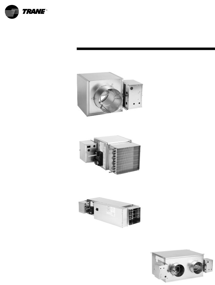
Figure 1 –Typical Single-Duct Units |
|
The basic unit consists of a sheet metal |
|
|
casing with an air valve, which is used |
|
|
to modulate the air being delivered into |
|
|
the occupied zone.The unit is designed |
|
|
to modulate either cooling or heating |
|
|
air between the temperatures of 40°F |
|
|
and 140°F.Air enters the air valve |
|
|
through the round or rectangular inlet |
|
|
and exits into the sheet metal casing to |
|
|
be distributed to the zone either |
|
|
through integral round outlets in the |
|
|
casing or through rectangular duct |
|
|
attached to the discharge of the unit. |
VCCF |
|
The basic unit can also be ordered with |
||
|
||
factory-mounted electric or hot water |
|
|
heating coils attached to the discharge. |
|
|
(See Figure 1.) |
|
|
These re-heat units are used primarily |
|
|
to reheat air-to-zone temperature when |
|
|
the load in the occupied space is low. |
|
|
Primary air is modulated through the |
|
|
VariTrane air valve by rotating the |
|
|
damper blade. All air valves have a |
|
|
round/rectangular inlet for easy fit-up |
|
|
with incoming ductwork. |
|
|
|
VCWF |
VCEF
Dual-Duct Units
Dual-duct units provide two air valves: one as heating primary air and the other as cooling primary air. Both discharge into the common outlet, which leads to the zone being controlled. (See Figure 2.)
The units are provided with a slip and drive rectangular duct connection or can be ordered with integral outlet plenum.
Sequencing of the hot and cold air valve is dependent upon job requirements. One typical control is the valves working in conjunction with each other to respond to zone temperature.
When the cooling valve becomes fully closed or reaches a specified minimum, then the heating valve will begin to modulate or vice versa.The typical result is that air flowing to the zone varies from the maximum down to a minimum and back up to a maximum as the load varies and as the controls would cause one air valve to close and the other to open.
Another typical application is when the unit provides a constant volume to the zone.When the zone sensor is tied directly to the heating valve, it will modulate the heating valve according to the zone temperature.
When the heating valve is fully closed or there is a call for cooling in the zone, the cooling valve will be at constant supply. As the space becomes too cool, the heating valve will modulate open, decreasing the cooling valve flow.The typical result is that the air flowing into the zone stays at a constant flow whether the unit is heating or cooling.
Figure 2 –Typical Dual-Duct Unit
VDDF
16 |
VAV-SVN01E-EN |

Unit
Information
Fan-Powered and Fan-Powered Low-Height Units
VariTrane fan-powered and low-height fan-powered units can be either parallel or series, with or without re-heat. (See Figure 3.)
The fan on a series unit runs continuously whenever the main air handler unit is in operation.There are various options for starting the fan.The fan can be started three ways: 1) remotely, 2) by a duct pressure switch, or 3) by a combination of both.The particular fan control method may vary from unit to unit, depending upon job needs.
Typically, the heater is off while the air valve modulates primary air and responds to zone temperature. If zone temperature decreases to the point where a decrease in primary air will not maintain the desired temperature, the re-heat will be activated to increase the temperature of the discharge air.
On a parallel unit, theVariTrane air valve delivers primary cooling air to the unit outlet.When the space temperature decreases beyond air valve control, the fan is turned on as the first stage of heat.The fan delivers plenum air from above the occupied space to the unit outlet, which is mixed with primary air and delivered to the occupied space.
Note: Either the fan, the air valve, or both can deliver airflow into the occupied space. In order to prevent primary airflow from exiting through the fan when the fan is not running on a parallel unit, a back draft damper is provided. When the fan is not running, the efficiency of this system is the same as a standard singleductVAV unit.
Typically, the control systems applied to parallel units cause the air valve to close to zero or a minimum flow before the fan is activated. After the fan is activated, the optional heat will be activated upon further reduction in zone temperature.Therefore, minimal primary air is mixed with the heated air.
VariTrane fan-powered unit fan sizes 02SQ–05SQ and 08SQ–10SQ were performance tested at .12 in. w.g. and sizes 06SQ and 07SQ were tested at .15 in. w.g. Units are not designed to operate unducted and below these tested static pressures.
Note: Fan-powered units are available with rectangular discharge connection only. The optional heater is mounted on the discharge of the unit. Hot water coils are connected to either the plenum inlet or on the discharge on parallel units, and to the discharge of series units.
Figure 3 –Typical Fan-Powered Units
VSCF |
VPCF |
VSEF |
VPEF |
VSWF |
VPWF |
VAV-SVN01E-EN |
17 |
Unit
Installation
Due to their weight, theVAV terminal units should be suspended from the uppermost ceiling, independent of the false ceiling grid. Suspension devices are to be supplied by the installer. Units must be installed level and upright. Failure to level the unit properly may prevent proper operation of the controls and/or terminal unit. Units are not designed to be installed vertically. Consequently, this will also void the UL ratings and any warranty on the unit.
Single-Duct
Depending upon the size and weight of the single-duct unit, it may be capable of being supported by the ductwork that is connected to it. No hanger brackets are provided on these units since the unit should be supported by means of a hanger strap.The hanger strap should be secured directly to the unit casing as shown in Figure 4.
For cooling only single-duct units or single-duct units with hot water coil, the unt may be rotated 180° for opposite side connections.
For units with electric heat, the unit must be ordered from the factory designating either rightor left-hand connections.
Figure 4
Single-Duct Hanging
Recommendations
Dual-Duct
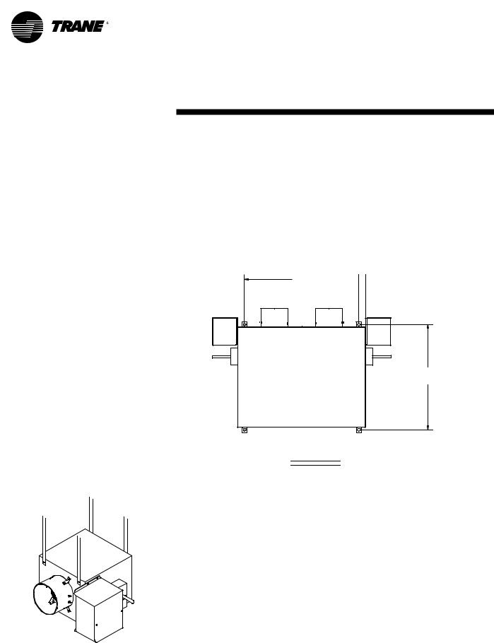
Dual-duct units should be supported by either hanger straps or by using a threaded rod in conjunction with the hanger brackets that are provided on the unit. See Figure 5.
Figure 5
Dual-Duct Hanger Bracket Locations
A 
 C
C
AIR |
AIR |
VALVE |
VALVE |
COOLING |
HEATING |
B
TOP VIEW
Inlet Size |
A |
B |
C |
|
|
|
|
5" thru 10" |
23.154" (588 mm) |
25.25" (641 mm) |
1.376" (35 mm) |
|
|
|
|
12" thru 16" |
25.154" (639 mm) |
37.25" (946 mm) |
1.376" (35 mm) |
|
|
|
|
18 |
VAV-SVN01E-EN |
 Loading...