


 Loading...
Trane SCWG-020, SCWG-025, SCWG-030, SCWG-032, SCWG-035 Installation and Maintenance Manual
...Installation, Operation,
and Maintenance
Intellipak™
Commercial Self-Contained
Modular Series 20 to 35Tons
Models |
SCWG -020, -025, -030, -032, -035 |
|
SIWG -020, -025, -030, -032, -035 |
|
SCRG -020, -025, -032 |
|
SIRG -020, -025, -032 |
 SAFETY WARNING
Only qualified personnel should install and service the equipment. The installation, starting up, and servicing of heating, ventilating, and air-conditioning equipment can be hazardous and requires specific knowledge and training. Improperly installed, adjusted or altered equipment by an unqualified person could result in death or serious injury. When working on the equipment, observe all precautions in the literature and on the tags, stickers, and labels that are attached to the equipment.
June 2014 |
SCXG-SVX01H-EN |
Introduction
Read this manual thoroughly before operating or servicing this unit.
Warnings, Cautions, and Notices
Safety advisories appear throughout this manual as required.Your personal safety and the proper operation of this machine depend upon the strict observance of these precautions.
The three types of advisories are defined as follows:
 WARNING
 CAUTIONs
NOTICE
Indicates a potentially hazardous situation which, if not avoided, could result in death or serious injury.
Indicates a potentially hazardous situation which, if not avoided, could result in minor or moderate injury. It could also be used to alert against unsafe practices.
Indicates a situation that could result in equipment or property-damage only accidents.
Important Environmental Concerns
Scientific research has shown that certain man-made chemicals can affect the earth’s naturally occurring stratospheric ozone layer when released to the atmosphere. In particular, several of the identified chemicals that may affect the ozone layer are refrigerants that contain Chlorine, Fluorine and Carbon (CFCs) and those containing Hydrogen, Chlorine, Fluorine and Carbon (HCFCs). Not all refrigerants containing these compounds have the same potential impact to the environment.Trane advocates the responsible handling of all refrigerants-including industry replacements for CFCs such as HCFCs and HFCs.
Important Responsible Refrigerant
Practices
Trane believes that responsible refrigerant practices are important to the environment, our customers, and the air conditioning industry. All technicians who handle refrigerants must be certified.The Federal Clean Air Act (Section 608) sets forth the requirements for handling, reclaiming, recovering and recycling of certain refrigerants and the equipment that is used in these service procedures. In addition, some states or municipalities may have additional requirements that must also be adhered to for responsible management of refrigerants. Know the applicable laws and follow them.
 WARNING
Refrigerant under High Pressure!
System contains oil and refrigerant under high pressure. Recover refrigerant to relieve pressure before opening the system. See unit nameplate for refrigerant type. Do not use non-approved refrigerants, refrigerant substitutes, or refrigerant additives. Failure to recover refrigerant to relieve pressure or the use of nonapproved refrigerants, refrigerant substitutes, or refrigerant additives could result in an explosion which could result in death or serious injury or equipment damage.
 WARNING
Personal Protective Equipment (PPE)
Required!
Installing/servicing this unit could result in exposure to electrical, mechanical and chemical hazards.
•Before installing/servicing this unit, technicians MUST put on all PPE required for the work being undertaken (Examples; cut resistant gloves/sleeves, butyl gloves, safety glasses, hard hat/bump cap, fall protection, electrical PPE and arc flash clothing). ALWAYS refer to appropriate Material Safety Data Sheets (MSDS)/Safety Data Sheets (SDS) and OSHA guidelines for proper PPE.
•When working with or around hazardous chemicals, ALWAYS refer to the appropriate MSDS/SDS and OSHA/GHS (Global Harmonized System of Classification and Labelling of Chemicals) guidelines for information on allowable personal exposure levels, proper respiratory protection and handling instructions.
•If there is a risk of energized electrical contact, arc, or flash, technicians MUST put on all PPE in accordance
with OSHA, NFPA 70E, or other country-specific requirements for arc flash protection, PRIOR to servicing the unit. NEVER PERFORM ANY SWITCHING, DISCONNECTING, OR VOLTAGE TESTING WITHOUT PROPER ELECTRICAL PPE AND ARC FLASH CLOTHING. ENSURE ELECTRICAL METERS AND EQUIPMENT ARE PROPERLY RATED FOR INTENDED VOLTAGE.
Failure to follow instructions could result in death or serious injury.
© 2014Trane All rights reserved |
SCXG-SVX01H-EN |
Introduction
 WARNING
Proper Field Wiring and Grounding
Required!
Failure to follow code could result in death or serious injury. All field wiring MUST be performed by qualified personnel. Improperly installed and grounded field wiring poses FIRE and ELECTROCUTION hazards. To avoid these hazards, you MUST follow requirements for field wiring installation and grounding as described in NEC and your local/state electrical codes.
NOTICE:
Use Copper Conductors Only!
Unit terminals are not designed to accept other types of conductors. Failure to use copper conductors could result in equipment damage.
Copyright
This document and the information in it are the property of Trane, and may not be used or reproduced in whole or in part without written permission.Trane reserves the right to revise this publication at any time, and to make changes to its content without obligation to notify any person of such revision or change.
Trademarks
Trane, Intellipak,Tracer and theTrane logo are trademarks ofTrane in the United States and other countries.All trademarks referenced in this document are the trademarks of their respective owners.
Revision History
SCXG-SVX01H-EN (24 Jun 2014)
Updated to correct input line current for 575V, 15HP, with bypass.
SCXG-SVX01G-EN (23 Oct 2012)
Updated fan motor FLA data.
SCXG-SVX01H-EN |
3 |

Table of Contents
Model Number Descriptions . . . . . . . . . . . . . . 6
Modular Series Self-Contained . . . . . . . . . . 6
Self-Contained Ship-With Accessory Model
Number . . . . . . . . . . . . . . . . . . . . . . . . . . . . . . 8
Remote Air-Cooled Condenser . . . . . . . . . . 8
General Data . . . . . . . . . . . . . . . . . . . . . . . . . . . . 9
Modular Series Self-Contained Unit
Components . . . . . . . . . . . . . . . . . . . . . . . . . . 9
General Data . . . . . . . . . . . . . . . . . . . . . . . . . 11
Pre-Installation Considerations . . . . . . . . . . . 13
Receiving . . . . . . . . . . . . . . . . . . . . . . . . . . . . 13
Contractor Installation Responsibilities . . 13
Unpackaging . . . . . . . . . . . . . . . . . . . . . . . . . 13
Dimensions & Weights . . . . . . . . . . . . . . . . . . 16
Service Clearances . . . . . . . . . . . . . . . . . . . . 24
Installation - Mechanical . . . . . . . . . . . . . . . . 25
Unit Handling Procedures . . . . . . . . . . . . . 25
Skid Removal . . . . . . . . . . . . . . . . . . . . . . 27
Installation Preparation . . . . . . . . . . . . . . . . 27
Split-Apart Unit Assembly . . . . . . . . . . . . 28
Unit Vibration Isolator Option . . . . . . . . . . 29
Duct Connections . . . . . . . . . . . . . . . . . . . . . 30
Plenum . . . . . . . . . . . . . . . . . . . . . . . . . . . . . . 30
Airside Economizer Installation . . . . . . . . . 31
Water Piping . . . . . . . . . . . . . . . . . . . . . . . . . 32
Condenser Connections . . . . . . . . . . . . . . 32
Condensate Drain Connections . . . . . . . . 32
General Waterside Recommendations:
Cooling Towers . . . . . . . . . . . . . . . . . . . . 32
Waterside Piping Arrangements . . . . . . . 33
Water Temperature Requirements . . . . . 33
Waterside Economizer Installation
Procedure . . . . . . . . . . . . . . . . . . . . . . . . . . . 34
Waterside Economizer with right-hand factory piping components . . . . . . . . . . . 35
Hydronic Coil Installation . . . . . . . . . . . . . . 36
Refrigerant System . . . . . . . . . . . . . . . . . . . 36
Interconnecting Piping . . . . . . . . . . . . . . . 37
Preliminary Refrigerant Charging . . . . . . . 37
Installation - Electrical . . . . . . . . . . . . . . . . . . . .39
Unit Wiring Diagrams . . . . . . . . . . . . . . . . . .39
Supply Power Wiring . . . . . . . . . . . . . . . . . .39
Selection Procedures . . . . . . . . . . . . . . . . . .40
Variable Frequency Drive Option (VFD) . . .41 Variable Frequency Drive Without ByPass 41 Variable Frequency Drive With ByPass . .45
Static Pressure Transducer Installation
(VAV units only) . . . . . . . . . . . . . . . . . . . . . . .49
Electric Heat Installation . . . . . . . . . . . . . . . .49
Standard with All IntelliPak Units . . . . . . .51
Zone Sensor Options for IntelliPak
Control Units . . . . . . . . . . . . . . . . . . . . . . . . .51 CV and VAV Unit Zone Sensor Options . .52
Integrated Comfort™ Systems Sensors
for CV and VAV Applications . . . . . . . . . . . .52
Zone Sensor Installation . . . . . . . . . . . . . . . .53
Programmable Zone Sensors . . . . . . . . . . .54
Time Clock Option . . . . . . . . . . . . . . . . . . . . .56
Remote Human Interface Panel Installation 56
Mounting the Remote Human Interface |
|
(RHI) Panel . . . . . . . . . . . . . . . . . . . . . . |
. . . . .57 |
Wiring the Remote Human Interface |
. . . . .59 |
Connecting to Tracer Summit . . . . . . |
. . . . .61 |
Programming the Time Clock Option |
. . . . .61 |
Operating Principals . . . . . . . . . . . . . . . . |
. . . . .63 |
Control Sequences of Operation . . . . |
. . . . .63 |
Unoccupied Sequence of Operation . |
. . . . .63 |
Occupied Sequence . . . . . . . . . . . . . . . |
. . . . .64 |
Thermostatic Expansion Valve . . . . . |
. . . . .66 |
Compressors . . . . . . . . . . . . . . . . . . . . |
. . . . .66 |
Unit Airside Components . . . . . . . . . . |
. . . . .71 |
Controls . . . . . . . . . . . . . . . . . . . . . . . . . . . |
. . . . .74 |
Points List . . . . . . . . . . . . . . . . . . . . . . . |
. . . . .74 |
RTM Module . . . . . . . . . . . . . . . . . . . |
. . . . .74 |
GBAS Module . . . . . . . . . . . . . . . . . . |
. . . . .74 |
ECEM Module . . . . . . . . . . . . . . . . . . |
. . . . .74 |
Tracer™ LCI-I Module . . . . . . . . . . . . . |
. . . . .74 |
Constant Volume (CV) Points . . . . . |
. . . . .74 |
4 |
SCXG-SVX01H-EN |

Table of Contents
Variable Air Volume (VAV) Points . |
. . . . . 75 |
BCI-Points List . . . . . . . . . . . . . . . . . . . |
. . . . . 76 |
Phase Monitor . . . . . . . . . . . . . . . . . . |
. . . . . 76 |
Unit Control Components . . . . . . . . . |
. . . . . 76 |
RTM Module Board - |
|
Standard on all Units . . . . . . . . . . . |
. . . . . 76 |
Compressor Module (MCM) - |
|
Standard on all Units . . . . . . . . . . . |
. . . . . 78 |
Human Interface Module - |
|
Standard on all Units . . . . . . . . . . . |
. . . . . 78 |
Remote Human Interface Module Option 78 |
|
Waterside Module - |
|
Standard on all water-cooled units |
. . . . . 78 |
Heat Module . . . . . . . . . . . . . . . . . . |
. . . . . 78 |
Ventilation Override Module |
|
(VOM) Option . . . . . . . . . . . . . . . . . |
. . . . . 78 |
Trane IntelliPak Communications |
|
Modules . . . . . . . . . . . . . . . . . . . . . |
. . . . . 79 |
Exhaust/Comparative Enthalpy (ECEM) |
|
Module . . . . . . . . . . . . . . . . . . . . . . |
. . . . . 80 |
Ventilation Control Module (VCM) |
. . . . . 80 |
Generic Building Automation System |
|
Module Option . . . . . . . . . . . . . . . . |
. . . . . 80 |
Input Devices and System Functions . . . 82 |
|
Pre-Startup . . . . . . . . . . . . . . . . . . . . . . . . |
. . . . . 85 |
Pre-Startup Checklist . . . . . . . . . . . . . |
. . . . . 85 |
Start-up . . . . . . . . . . . . . . . . . . . . . . . . . . . |
. . . . . 86 |
Final Refrigerant Charge . . . . . . . . . . |
. . . . . 87 |
Start-up Procedure . . . . . . . . . . . . . . . |
. . . . . 87 |
Startup Log . . . . . . . . . . . . . . . . . . . . . |
. . . . . 88 |
Maintenance . . . . . . . . . . . . . . . . . . . . . . |
. . . . . 90 |
Service Access . . . . . . . . . . . . . . . . . . |
. . . . . 90 |
Variable Frequency Drive (VFD) . . |
. . . . . 90 |
Variable Frequency Drive (VFD) - |
|
Remote Mounted . . . . . . . . . . . . . . |
. . . . . 90 |
Air Filters . . . . . . . . . . . . . . . . . . . . . . . |
. . . . . 90 |
Inspecting and Cleaning Drain Pan . |
. . . . . 90 |
Inspecting and Cleaning the Fan . . . |
. . . . . 91 |
Supply Fan . . . . . . . . . . . . . . . . . . . . . |
. . . . . 91 |
Fan Drive . . . . . . . . . . . . . . . . . . . . . |
. . . . . 91 |
Fan Bearings . . . . . . . . . . . . . . . . . . |
. . . . . 92 |
Fan Belt Tension . . . . . . . . . . . . . . . |
. . . . . 93 |
Adjusting Belt Tension . . . . . . . . . . . . . . .94
Refrigerant System . . . . . . . . . . . . . . . . . . . .95
Refrigerant Leak Test Procedure . . . . . . . .95
Brazing Procedures . . . . . . . . . . . . . . . . . .96
System Evacuation Procedures . . . . . . . .97
Compressors . . . . . . . . . . . . . . . . . . . . . . . . .98
Scroll Compressor Failure Diagnosis
and Replacement . . . . . . . . . . . . . . . . . . . .98
Components . . . . . . . . . . . . . . . . . . . . . . . . . .99
Coil Fin Cleaning . . . . . . . . . . . . . . . . . . . . .100
Piping Components . . . . . . . . . . . . . . . . . . .102
Maintenance Periodic Checklists . . . . . . . .102
Diagnostics . . . . . . . . . . . . . . . . . . . . . . . . . . . .104
Troubleshooting . . . . . . . . . . . . . . . . . . . . . .104
System Checks . . . . . . . . . . . . . . . . . . . . .104
Diagnostics . . . . . . . . . . . . . . . . . . . . . . . . . .104
Wiring Diagrams . . . . . . . . . . . . . . . . . . . . . . .113
SCXG-SVX01H-EN |
5 |

Model Number Descriptions
Modular Series Self-
Contained
Digit 1 - Unit Model
S = self contained
Digit 2 - Unit Type
C |
= |
commercial |
I |
= |
industrial |
Digit 3 - Condenser Medium
W |
= |
water-cooled |
R |
= |
remote air-cooled |
Digit 4 - Development Sequence
G = modular series
Digit 5 - Refrigerant Circuit Configuration
U = independent, R-410A refrigerant
Digits 6, 7 - Unit Nominal Capacity
20 = 20Tons (water or air cooled)
25 = 25Tons (water or air cooled)
30 = 30Tons (water cooled only)
32 = 32Tons (air cooled only)
35 = 35Tons (water cooled only)
Digit 8 - Unit Voltage
6 = 200 volt/60 hz/3 ph
4= 460 volt/60 hz/3 ph
5= 575 volt/60 hz/3 ph
Digit 9 - Air Volume/Temp
Control
2= I-Pak & VFD & supply air temp
ctrl
3= I-Pak & VFD w/ bypass & supply air temp ctrl
4= I-Pak w/o vol. ctrl, w/ zone temp cool
5= I-Pak w/o vol. ctrl, w/ zone temp heat/cool
6= I-Pak w/o vol. ctrl, w/ supply air temp ctrl
8 = thermostat interface
Digits 10, 11 - Design Sequence
** = Factory Assigned
Digit 12 - Unit Construction
A= vertical discharge
B= vertical discharge with double wall
C= horizontal discharge
D= horizontal discharge w/ double wall
E= vertical discharge, ship separate
F= vert. dis. w/ double wall,
ship sep.
G= horizontal discharge, ship separate
H= horiz. dis. w/ double wall, ship sep.
Digit 13 - Plenum Type
B= std plenum w/ factory cut holes
C= low plenum w/ factory cut holes
E= std plenum w/ field cut holes
F= low plenum w/ field cut holes
H= std plenum double wall (perf) w/ field cut holes
J= low plenum double wall (perf) w/ field cut holes
L= std. plenum w/factory cut holes, ship separate
M= low plenum w/ factory cut holes, ship separate
P = std plenum w/ field cut holes, ship
separate
R= low plenum w/ field cut holes, ship separate
U= std plenum double wall (perf) w/ field cut holes, ship separate
V= low plenum double wall (perf) w/ field cut holes, ship separate
0 = without plenum
Digit 14 - Motor Type
2= ODP motor
3= TEFC motor
Digits 15, 16 - Motor HP
05 |
= |
5 hp |
07 |
= |
7.5 hp |
10 |
= |
10 hp |
15 |
= |
15 hp |
20 |
= |
20 hp |
25 |
= |
25 hp |
Digits 17, 18, 19 - Fan RPM
085 |
= |
850 rpm |
090 |
= |
900 rpm |
095 |
= |
950 rpm |
100 |
= |
1000 rpm |
105 |
= |
1050 rpm |
110 |
= |
1100 rpm |
115 |
= |
1150 rpm |
120 |
= |
1200 rpm |
125 |
= |
1250 rpm |
130 |
= |
1300 rpm |
135 |
= |
1350 rpm |
140 |
= |
1400 rpm |
145 |
= |
1450 rpm |
150 |
= |
1500 rpm |
155 |
= |
1550 rpm |
160 |
= |
1600 rpm |
165 |
= |
1650 rpm |
170 |
= |
1700 rpm |
175 |
= |
1750 rpm |
180 |
= |
1800 rpm |
185 |
= |
1850 rpm |
Digit 20 - Heating Type
A= steam coil, LH
B= hot water coil, LH
C= electric heat, 1 stage
F= hydronic heat ctrl interface
G= elec. heat ctrl interface,1 stage
K= steam coil ship separate, LH
L= hot water coil ship separate, LH
M= steam coil, RH
N= hot water coil, RH
P |
= |
steam coil ship separate, RH |
R |
= |
hot water coil ship separate, RH |
T |
= |
hi-cap. hot water coil, LH |
U |
= |
hi-cap hot water coil, LH, ship |
sep |
|
|
V= hi-cap hot water coil, RH
W= hi-cap hot water coil, RH, ship
sep
0 = none
Digit 21 - Unit Isolators
A |
= |
isopads |
B |
= |
spring isolators |
0 |
= |
none |
Digit 22 - Unit Finish
1= paint - slate gray
2= protective coating
3= protective coating w/ finish coat
Digit 23
0 = none
Digit 24 - Unit Connection
1= disconnect switch
2= terminal block
3= dual point power
Digit 25 - Industrial Options
A= protective coated evaporator coil
B= silver solder
C= stainless steel screws
D= A and B
E= A and C
F= B and C
G= A, B and C
0 = none
Digit 26 - Drain Pan Type
A= galvanized sloped
B= stainless steel sloped
Digit 27 - Waterside Economizer
A= mechanical clean full capacity (4-row)
B= mechanical clean low capacity (2-row)
C= chemical clean full capacity
(4-row)
D= chemical clean low capacity (2-row)
E= mechanical clean full capacity (4-row) ship separate
F= mechanical clean low capacity (2-row) ship separate
G= chemical clean full capacity
(4-row) ship separate
H= chemical clean low capacity (2-row) ship separate
0 = none
6 |
SCXG-SVX01H-EN |

Model Number Descriptions
Digit 28 - Ventilation Control
B= airside econ w/Traq™ damper (top O/A inlet)
C= airside econ w/ standard dampers (top O/A inlet)
E= airside econ w/Traq™ damper and comparative enthalpy (top O/A)
F= airside econ w/ std dampers and comparative enthalpy (top O/A)
H= none/ventilation for 2-position control interface
J= airside economizer interface
K= airside economizer interface w/ comparative enthalpy
0 = |
None |
Digit 29 - Water Piping
A= RH condenser connection
B= LH condenser connection
C= RH basic piping
D= LH basic piping
E= RH intermediate piping
F= LH intermediate piping
J= RH basic w/ flow switch
K= LH basic w/ flow switch
L= RH intermediate w/ flow switch
M= LH intermediate w/ flow switch 0 = none
Digit 30 - Condenser Tube Type
A= standard condenser tubes
B= 90/10 CuNi condenser tubes 0 = none
Digit 31 - Compressor Service
Valves
1 |
= |
with service valves |
0 |
= |
none |
Digit 32 - Miscellaneous System Control
1 = timeclock
2= interface for remote HI (IPCB)
3= dirty filter switch
4= 1 and 2
5= 1 and 3
6= 2 and 3
7= 1, 2, and 3
0 = none
Digit 33 - Control Interface
Options
A= Generic BAS Module; 0-5 VDC (GBAS)
B= Ventilation Override Module (VOM)
D = Remote Human Interface (RHI)
G= GBAS & VOM
H= GBAS & RHI
J = VOM & RHI
M= GBAS & VOM & RHI
N= BACnet Communications Interface (BCI)
P= BCI and GBAS
Q= BCI and VOM
R= BCI and RHI
T |
= |
BCI and GBAS and VOM |
U |
= |
BCI and GBAS and RHI |
V= BCI and VOM and RHI
W= BCI and GBAS and VOM and RHI
0 = None
1= LonTalk Comm5 Interface (LCI)
2= LCI and GBAS
3= LCI and VOM
4= LCI and RHI
5= LCI and GBAS and VOM
6= LCI and GBAS and RHI
7= LCI and VOM and RHI
8= LCI and GBAS and VOM and RHI
Digit 34 - Agency
T = UL agency listing 0 = none
Digit 35 - Filter Type
1= 2-inch construction throwaway
2= 2-inch med eff. throwaway
Digit 36 - Miscellaneous Control
Option
A= low entering air temp. protect device (LEATPD)
B= high duct temp t-stat
C= plenum high static switch
D= kit for heat mode output (w/t’stat)
E= A and B
F= A and C
G= B and C
H= A, B, and C
0 = None
SCXG-SVX01H-EN |
7 |

Model Number Descriptions
Self-Contained Ship-
With Accessory
Model Number
Digit 1 - Parts/Accessories
P = parts/accessories
Digit 2 - Unit Model
S = self-contained
Digit 3 - Shipment
W = with unit
Digit 4 - Development Sequence
F= signature series
G= modular series
Digit 5 - Sensors and Other
Accessories
S = sensors
Digit 6 - Sensors and
Thermostats (Field Installed)
A= BAYSENS077 - zone temp only (CV and VAV)
B= BAYSENS073zone temp with timed override button (CV and VAV)
C= BAYSENS074 - zone temp with timed override button, setpoint dial (CV and VAV)
E= BAYSENS108 - CV zone sensor -dual setpoint, man/auto changeover
F= BAYSENS110 - CV zone sensordual setpoint, man/auto changeover w, indicastor lights
G= BAYSENS119 - CV/VAV programmable night setback Sensor
H= BAYSENS021 - VAV zone sensor with indicator lights
K= BAYSTAT150 2H/2C ProgTstat w/ BAYSTAT077 Remote Sensor
L= outside air temperature sensor
kit
M= outside air humidity sensor kit
N= BAYSTAT155 3H/2CTstat
P= BAYSTAT150 2H/2C ProgrammableTstat
0 = none
Digit 7 - Mixed Air Temperature
Protection Kit (Field Installed)
1= mixed air temperature protection kit
0 = none
Digit 8 - Carbon Dioxide Sensor
(Field Installed)
1 |
= |
carbon dioxide sensor kit |
0 |
= |
none |
Digit 9 - Future Option
0 = none
Digits 10, 11 - Design Sequence
** = Factory Assigned
Remote Air-Cooled
Condenser
Digit 1 - Unit Model
C = Condenser
Digit 2 - Unit Type
C |
= |
Commercial |
I |
= |
Industrial |
Digit 3 - Condenser Medium
R = Remote
Digit 4 - Development Sequence
C = C
Digits 5, 6, 7 - Nominal Capacity
020 = 20Tons
029 = 29Tons
032 = 32Tons
Digit 8 - Unit Voltage
4= 460 Volt/60 Hz/3 ph
5= 575 Volt/60 Hz/3 ph
6= 200 Volt/60 Hz/3 ph
Digit 9 - Control Option
0 = No Low Ambient, I-Pak
A= No Low Ambient,T-stat
B= Low Ambient, I-Pak
C= Low Ambient,T-stat
Digits 10, 11 - Design Sequence
** = Factory Assigned
Digit 12 - Unit Finish
1= Paint (Slate Gray)
2= Protective Coating
3= Protective Coating with Finish Coat
4= Unpainted Unit
Digit 13 - Coil Options
A |
= |
Non-Coated Aluminum |
C |
= |
Protective Coated Aluminum |
Digit 14 - Unit Isolators
0 = None
A= Spring Isolators
B= Isopads
Digit 15 - Panels
0 |
= |
None |
1 |
= |
Louvered Panels |
Digit 16 - Agency
0 |
= |
None |
T |
= |
UL Listing |
8 |
SCXG-SVX01H-EN |

General Data
Modular Series Self-Contained
Unit Components
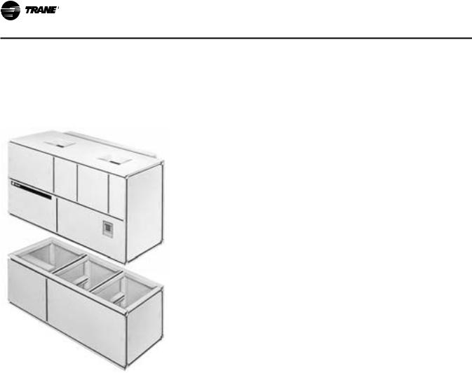
Commercial self contained units are complete HVAC systems used in floor-by-floor applications. Units are easy to install because they feature a single point power connection, factory installed and tested controls, single water point connection, factory installed options, and an internally trapped drain connection. Modular selfcontained units can ship as split-apart units for installation ease. Split-apart units ship with a dry nitrogen charge and require field refrigerant charging.
Units consist of multiple hermetically sealed 3-D scroll compressors, water-cooled condensers (water-cooled units only), an evaporator coil, dual forward curved fans, and control panel. Air-cooled units require a remote aircooled condenser, model CXRC. Unit controls are either electromechanical thermostat or microprocessor controls on IntelliPak unit.
Hermetically sealed 3-D scroll compressor motors utilize internal motor protection and time delays to prevent excessive cycling.
Water-cooled condensers are shell and tube type with internal subcooler. Condensers are available as mechanically or chemically cleanable. Evaporator fan is double width, double inlet and forward curved with a fixed pitch belt drive assembly. Variable frequency drives are optional. EISA efficiency open drip proof (ODP) and totally enclosed fan cooled (TEFC) motor options are available.
Package water-cooled units ship with full refrigerant and compressor oil charge. Split apart water cooled, and air cooled, units ship with dry nitrogen charge and complete compressor oil charge.
Split apart water cooled units require field connection of suction and liquid lines. Air-cooled units require fieldpiping discharge and liquid lines to remote air cooled condenser.
All units have two refrigerant circuits that include filter drier (field installed in air cooled), liquid line service valve, sight glass/moisture indicator, thermal expansion valve with a sensing bulb and external equalizing line, suction and discharge line access ports, and high and low pressure cutout switches. Water-cooled units also include pressure relief valve. Air cooled units include liquid line solenoid valve and discharge line check valve.
Control Options
Units may be ordered with conventional thermostat interface or IntelliPak™ Direct Digital Control (DDC). IntelliPak controls include a Human Interface (HI) panel with two line by forty (40) character clear English display for easy operator interface to unit setup and control parameters. All basic setup parameters are preset from factory.
Human Interface Panel
HI is unit mounted and accessible without opening unit’s front panel. It allows easy setpoint adjustment using HI keypad. HI displays all unit operating parameters and conditions in a clear language display, which can be configured for either English, French, or Spanish.
Optional remote human interface (RHI) will control up to four self-contained units, each containing an interprocessor communications bridge (IPCB). It has the same features as unit-mounted HI except for service mode.
For more information on setpoint defaults, ranges and unit programming, see IntelliPak Self-Contained Programming Guide, PKG-SVP01*-EN that ships with each unit.
IntelliPak™ DDC Control
IntelliPak™ DDC Control provides “smart” unit control with safety features and control relays for pumps, dampers, etc. Modular Series IntelliPak self-contained unit is controlled by microelectronic control system consisting of a network of modules.These modules are referred to as unit control modules (UCM). In this manual, acronym UCM refers to the entire control system network.
These modules perform specific unit functions using proportional/integral control algorithms.They are mounted in the unit control panel and are factory wired to their respective internal components. Each module receives and interprets information from other unit modules, sensors, remote panels, and customer binary contacts to satisfy the applicable request; i.e., economizing, mechanical cooling, heating, ventilation. See the Operation section of this manual for a detailed description of each module’s function.
Optional Controls
Optional controls include a disconnect switch, dirty filter switch, water flow switch (water-cooled only), supply air temperature reset, or external setpoint inputs. Daytime heating is available on units with electric, steam, or hot water heat control options. Morning warmup operation is available on all units.
The static pressure probe, zone night heat/morning warmup, supply air temperature reset sensor options ship separate inside the unit control panel for field installation. For more detailed information on the unit control options, see the Owner’s section of this manual.
SCXG-SVX01H-EN |
9 |
General Data
Unit Nameplate
Unit nameplate, mounted on left end of unit control panel, identifies unit model number, service literature, and wiring diagram numbers.
Figure 1. IntelliPak™ commercial self-contained modular series unit
10 |
SCXG-SVX01H-EN |
General Data
General Data
Table 1. |
SCWG/SIWG/SCRG/SIRG general data |
|
|
|
|
|
|||
|
|
|
|
|
|
|
|
||
|
|
|
|
Water-Cooled Units |
|
|
Air-Cooled Units |
||
|
|
|
|
|
|
|
|
|
|
|
|
Unit Size |
20 |
25 |
30 |
35 |
20 |
25 |
32 |
|
|
|
|
|
|
|
|
|
|
|
Compressor Data |
|
|
|
|
|
|
|
|
|
|
Quantity |
2 |
2 |
1/1 |
2 |
2 |
1/1 |
2 |
|
Nominal Ton/Comp |
10 |
10 |
10/15 |
15 |
10 |
10/15 |
15 |
|
|
|
Circuits |
2 |
2 |
2 |
2 |
2 |
2 |
2 |
|
|
|
|
|
|
|
|
|
|
|
Evaporator Coil Data |
|
|
|
|
|
|
|
|
|
|
Rows |
2 |
4 |
4 |
4 |
3 |
4 |
4 |
|
|
Sq. Ft. |
22.5 |
25.0 |
25.0 |
25.0 |
25.0 |
25.0 |
25.0 |
|
|
FPF |
144 |
144 |
144 |
144 |
144 |
144 |
144 |
|
|
|
|
|
|
|
|
|
|
|
Condenser Data |
|
|
|
|
|
|
|
|
|
Minimum GPM w/o Econ |
36 |
36 |
46 |
54 |
- |
- |
- |
|
|
Minimum GPM w/ Econ |
41 |
41 |
60 |
65 |
- |
- |
- |
|
|
|
Maximum GPM |
80 |
80 |
102 |
119 |
- |
- |
- |
|
|
|
|
|
|
|
|
|
|
|
Evaporator Fan Data |
|
|
|
|
|
|
|
|
|
|
Quantity |
2 |
2 |
2 |
2 |
2 |
2 |
2 |
|
Size (Dia. x width - inches) |
12 5/8"x8" |
12 5/8"x9" |
12 5/8"x11" |
12 5/8 x11" |
12 5/8"x8" |
12 5/8"x9" |
12 5/8"x11" |
|
|
|
Minimum HP |
5 |
5 |
5 |
5 |
5 |
5 |
5 |
|
|
Maximum HP |
20 |
25 |
25 |
25 |
20 |
25 |
25 |
|
Minimum Design CFM |
6350 |
7250 |
7250 |
7250 |
7250 |
7250 |
7250 |
|
|
Maximum Design CFM |
8500 |
10,625 |
12,750 |
14,875 |
8500 |
10,625 |
13600 |
|
|
|
|
|
|
|
|
|
|
|
|
R-410A Refrigerant Data |
|
|
|
|
|
|
|
|
|
|
EER |
14.0 |
14.3 |
14.1 |
14.0 |
10.0 |
10.1 |
10.4 |
|
|
IEER (CV) |
14.1 |
14.8 |
15.4 |
15.6 |
10.8 |
11.8 |
11.9 |
|
|
IEER (VFD) |
17.1 |
18.1 |
18.2 |
17.7 |
13.4 |
13.3 |
13.8 |
|
Refrigerant Charge - lb (kg) |
|
|
|
|
|
|
|
|
|
|
Circuit A |
19.0 (8.6) |
24.0 (10.9) |
24.5 (11.1) |
23.0 (10.4) |
See Note 3 |
See Note 3 |
See Note 3 |
|
|
Circuit B |
19.0 (8.6) |
24.0 (10.4) |
23.0 (10.4) |
23.0 (10.4) |
See Note 3 |
See Note 3 |
See Note 3 |
|
Capacity Steps - % |
100/53/0 |
100/53/0 |
100/65/42/6 |
100/53/0 |
|
|
|
|
|
|
|
|
|
|
|
|
|
|
|
Filter Data |
|
|
|
|
|
|
|
|
|
|
Quantity |
4 |
4 |
4 |
4 |
4 |
4 |
4 |
|
|
Size (inches) |
16x25x2 |
16x25x2 |
16x25x2 |
16x25x2 |
16x25x2 |
16x25x2 |
16x25x2 |
|
|
Quantity |
4 |
4 |
4 |
4 |
4 |
4 |
4 |
|
|
Size (inches) |
20x25x2 |
20x25x2 |
20x25x2 |
20x25x2 |
20x25x2 |
20x25x2 |
20x25x2 |
|
|
|
|
|
|
|
|
|
|
|
CCRC/CIRC Condenser |
- |
- |
- |
- |
20 |
29 |
32 |
|
|
Match |
|
|||||||
|
|
|
|
|
|
|
|
|
|
|
|
|
|
|
|
|
|
|
|
Notes:
1.Compressors are Trane 3-D™scroll.
2.EER and IEER are rated in accordance to the AHRI Standard 340/360-2010. Based on 80/67°F (26.7/19.4°C) to the evaporator coil, nominal airflow and 85-95°F (29.4-35°C) condenser water or 95° F (35° C) ambient.
3.All units operate with R-410A. Water Cooled units ship with full operating charge. Air-cooled units ship with dry nitrogen charge. Field refrigerant system charge required. Refer to Table 2, p. 12 for amounts required.
4.Maximum cfm limits are set to prevent moisture carryover on the evaporator coil.
5.Minimum cfm limits are set to ensure stable thermal expansion valve operation at low load conditions.
6.Filter sizes are for units without hot water or steam heating coils
SCXG-SVX01H-EN |
11 |
General Data
Table 2. SCRG/SIRG self-contained and CCRC/CIRC remote air-cooled condenser
SCRG/SIRG & CCRC/CIRC |
|
|
|
Unit Size |
20/20 |
25/29 |
32/32 |
No. of Refrigerant Circuits |
2 |
2 |
2 |
Operating Charge - lbs R-410A |
36.5/36.5 |
48.5/36 |
46/46 |
Operating Charge - kg R-410A |
16.6/16.6 |
22/16.3 |
20.9/20.9 |
Cond. Storage Cap. - lbs R-410A |
37/37 |
51/37 |
51/51 |
Cond. Storage Cap. - kg R-410A |
16.8/16.8 |
23.1/16.8 |
23.1/23.1 |
Notes:
1.Refrigerant charges are listed as circuit 1/circuit 2 and provide only an estimate. Final charge requires sound field charging practice.
2.Operating charge estimate includes the air-cooled self-contained, remote air-cooled condenser, and 25 feet of interconnecting refrigerant piping.
3.At conditions of 95°F (35°C), condenser storage capacity is 95% full.
4.To determine the correct amount of refrigerant needed for a particular application, reference the Trane Reciprocating Refrigeration Manual.
5.Field piping over 25 feet requires additional refrigerant. See Table 25, p. 37 and Table 26, p. 38 to determine amounts.
Table 3. CCRC/CIRC remote air-cooled condenser general data
Unit Size |
20 |
29 |
32 |
|
|
|
|
|
|
Condenser Fan Data |
|
|
|
|
Number/Type/Drive 4/Prop/Direct |
4/Prop/Direct |
4/Prop/Direct |
||
Size (inches) |
26 |
26 |
26 |
|
HP ea. |
1 |
1 |
1 |
|
Nominal Cfm |
18,800 |
21,200 |
32,000 |
|
|
|
|
|
|
Condenser Coil Data |
|
|
|
|
Circuit 1 Size (in.) |
1/46x71 |
1/46x71 |
1/64x71 |
|
Circuit 2 No./Size (in.) |
1/46x71 |
1/64x71 |
1/64x71 |
|
Face Area (sq. ft.) |
45.4 |
54.2 |
63.1 |
|
Rows/fpf |
4/144 |
4/144 |
4/144 |
|
|
|
|||
Ambient Temperature Operating Range |
|
|||
Standard Ambient (°F) |
50-115 |
50-115 |
50-115 |
|
Low Ambient Option |
0-115 |
0-115 |
0-115 |
|
(°F) |
||||
|
|
|
||
|
|
|
|
|
Table 4. SCWG/SIWG/SCRG/SIRG self-contained heating coil
Filter Data for Heating Coil
Quantity |
4 |
|
|
|
|
|
Size (inches) |
20x18x2 |
|
|
|
|
|
Size (mm) |
(508x457x51) |
|
|
|
|
|
Quantity |
8 |
|
|
|
|
|
Size (inches) |
20x20x2 |
|
|
|
|
|
Size (mm) |
(508x508x51) |
|
|
|
|
|
|
|
|
|
|
|
|
|
|
Row |
No. |
No. |
|
|
Coil Data |
Type |
s |
Size (in) Size (mm) |
fpf |
||
Steam Coil |
NS |
1 |
2 |
2 |
|
|
609.6x1473. |
42 |
|||||
24 x 58 |
||||||
|
|
|
|
2 |
|
|
Hot Water Coil, |
5W |
1 |
1 |
1 |
80 |
|
std. cap |
48 x 62 |
1219 x 1575 |
||||
Hot Water Coil, |
5W |
2 |
1 |
1 |
108 |
|
hi-cap. |
48 x 62 |
1219 x 1575 |
||||
Notes:
1.Hot water and steam heating coils have Prima-Flo® fins and do not have turbulators.
2.For coil capacities, use TOPSS™ (Trane Official Product Selection Program).
Table 5. Waterside economizer coil physical data - SCXG 20, 25, 30, 35
|
|
|
Height |
Length |
Type |
Rows |
FPF |
(in) |
(in) |
|
|
|
|
|
Chemically Cleanable |
2 |
108 |
50 |
72 |
|
|
|
|
|
Mechanically Cleanable |
2 |
108 |
50 |
72 |
|
|
|
|
|
Chemically Cleanable |
4 |
108 |
50 |
72 |
|
|
|
|
|
Mechanically Cleanable |
4 |
108 |
50 |
72 |
|
|
|
|
|
12 |
SCXG-SVX01H-EN |

Pre-Installation Considerations
Receiving
Receiving Checklist
Complete the following checklist immediately after receiving unit shipment to detect possible shipping damage.
•Inspect individual cartons before accepting. Check for rattles, bent carton corners, or other visible indications of shipping damage.
•If a unit appears damaged, inspect it immediately before accepting the shipment. Make specific notations concerning the damage on the freight bill. Do not refuse delivery.
•Inspect the unit for concealed damage before it is stored and as soon as possible after delivery. Report concealed damage to the freight line within the allotted time after delivery. Check with the carrier for their allotted time to submit a claim.
•Do not move damaged material from the receiving location. It is the receiver’s responsibility to provide reasonable evidence that concealed damage did not occur after delivery.
•Do not continue unpacking the shipment if it appears damaged. Retain all internal packing, cartons, and crate.Take photos of damaged material if possible.
•Notify the carrier’s terminal of the damage immediately by phone and mail. Request an immediate joint inspection of the damage by the carrier and consignee.
Notify yourTrane representative of the damage and arrange for repair. Have the carrier inspect the damage before making any repairs to the unit.
Ship-Separate Accessories
Field-installed sensors ship separately inside unit’s main control panel. Extra filters, sheaves, and belts ship in unit’s fan motor section. Condenser plugs, spring isolators, and isopads ship in unit’s bottom left side.
Contractor Installation
Responsibilities
Complete the following checklist before beginning final unit installation.
•Verify the unit size and tagging with the unit nameplate.
•Make certain the floor or foundation is level, solid, and sufficient to support the unit and accessory weights. Level or repair the floor before positioning the unit if necessary.
•Allow minimum recommended clearances for routine maintenance and service. Allow space at end of the
unit for shaft removal and servicing. Refer to unit submittals for dimensions. See also “Service Clearances,” p. 24.
•Allow three fan diameters above the unit for the discharge ductwork. Return air enters the rear of the unit and conditioned supply air discharges through the top.
•Electrical connection knockouts are on the top, left side of the unit.
•Allow adequate space for piping access and panel removal. Condenser water piping, refrigerant piping, and condensate drain connections are on the lower left end panel.
Note: Unit height and connection locations will change if using vibration isolators.The unit height may increase up to 5 7/8” with spring type isolators.
•Electrical supply power must meet specific balance and voltage requirements as described in section “Installation - Electrical,” p. 39.
•Water-cooled units only:The installer is responsible for providing a condenser main, standby water pump, cooling tower, pressure gauges, strainers, and all components for waterside piping. See “Water Piping,” p. 32 for general waterside recommendations.
•Air-cooled units only:The installer is responsible for providing and installing the remote air-cooled condenser and refrigerant piping.
Unpackaging
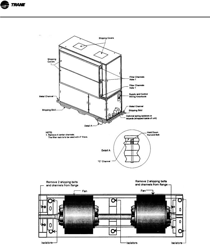
Commercial self-contained units ship assembled with protective coverings over the coil and discharge openings. Figure 2, p. 14 illustrates a typical shipping package.
Unit Protective Covers
Remove the shipping protection coverings from the human interface panel (HI) at the control panel, the filter box (or air inlet opening), the discharge air opening, and optional variable frequency drive (VFD).
Supply Fan Isolators
Remove the shipping channels and mounting bolts from beneath the fan. See Figure 4, p. 15. Open both fan compartment access doors to access the channels.There are four mounting points for 20-38 ton units.
Note: For 20-38 ton units, do not remove the fan assembly shipping blocks and tie down bolts if the fan speed is 750 rpm or less.
While keeping the fan mounting frame level, turn the fan isolator height adjusting bolts until the fan housing P- gasket compresses 1/4” against the roof transition piece. See Figure 4, p. 15.
SCXG-SVX01H-EN |
13 |
Pre-Installation Considerations
Figure 2. Typical unit mounting on shipping skid
Figure 3. Fan isolator locations
14 |
SCXG-SVX01H-EN |
Pre-Installation Considerations
Figure 4. Supply fan horizontal isolation shipping bracket
SCXG-SVX01H-EN |
15 |
Dimensions & Weights
Table 6. SCWG/SIWG weight, lbs.
Unit Tons |
Base Weight - lb (kg) |
|
|
20 |
2227 (1010) |
|
|
25 |
2697 (1223) |
|
|
30 |
2765 (1254) |
|
|
35 |
2834 (1286) |
Notes:
1.All unit weights include refrigerant, water and controllers, electric heat and valves.
2.Add 150 lbs. to total weight to obtain approximate shipping weight.
3.Split-apart unit weights are approximately: 60% total unit weight = compressor section, 40% total unit weight = fan section.
Table 7. SCRG/SIRG weight, lbs (kg)
unit tons |
base weight |
|
|
20 |
2311 (1048) |
|
|
25 |
2380 (1079) |
|
|
32 |
2448 (1110) |
Notes:
1.All unit weights include refrigerant, water and controllers, electric heat and valves.
2.Add 150 lbs. to total weight to obtain approximate shipping weight.
3.Split-apart unit weights are approximately: 60% total unit weight = compressor section, 40% total unit weight = fan section.
16 |
SCXG-SVX01H-EN |

Dimensions & Weights
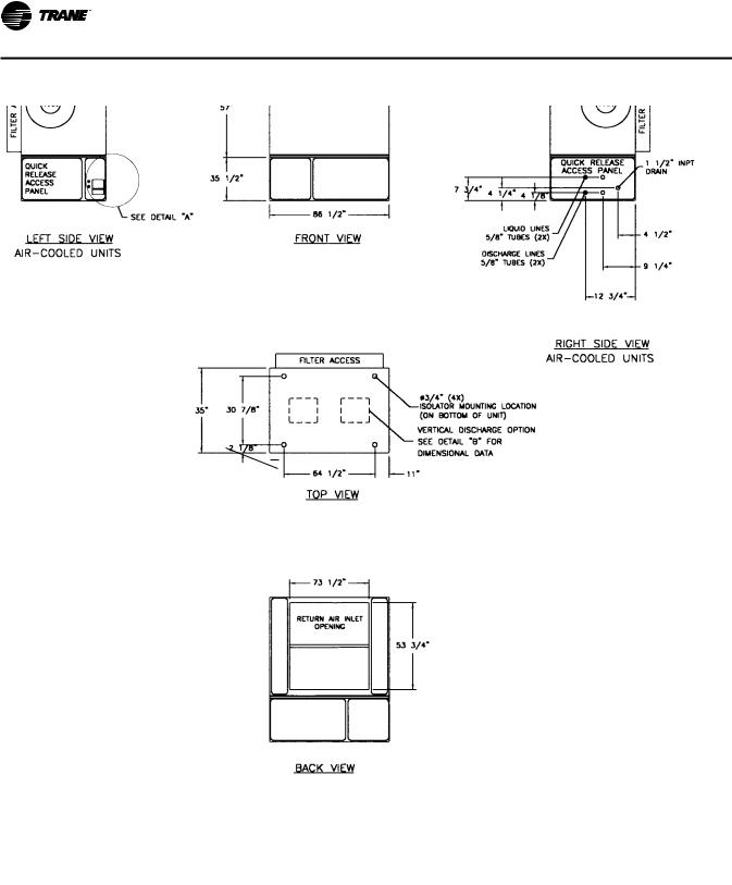
Figure 5. SCWG/SIWG, in.
6.75”
SCXG-SVX01H-EN |
17 |
Dimensions & Weights
Figure 6. SCRG/SIRG, in.
6.75”
18 |
SCXG-SVX01H-EN |

Dimensions & Weights
Table 8. Detail dimensions, in.
Model |
|
A |
|
B |
C |
D |
E |
|
F |
|
|
|
|
|
|
|
|
|
|
SCWG/SCRG |
20 |
20 |
10 |
3/4 |
58 1/2 |
5 1/8 13 |
1/4 11 |
1/2 |
|
|
|
|
|
|
|
|
|
||
SCWG/SCRG |
25 |
19 1/4 12 |
1/4 |
57 5/8 |
5 1/8 13 |
1/4 11 |
1/2 |
||
|
|
|
|
|
|
|
|
|
|
SCWG 30 - 35 |
18 |
14 |
5/8 |
56 1/2 |
5 1/8 13 |
1/4 |
11 |
1/2 |
|
SCRG 32 |
|
||||||||
|
|
|
|
|
|
|
|
|
|
Figure 7. SCRG/SIRG/SCWG/SIWG detail “A” electrical connections, in.
Note: When unit is ordered with horizontal supply, ensure that all applicable codes are considered when installing equipment. Special attention should be made to over head clearances of unit/ ducting to meet code requirements.
Figure 8. Detail “B” discharge options, in.
SCXG-SVX01H-EN |
19 |
Dimensions & Weights
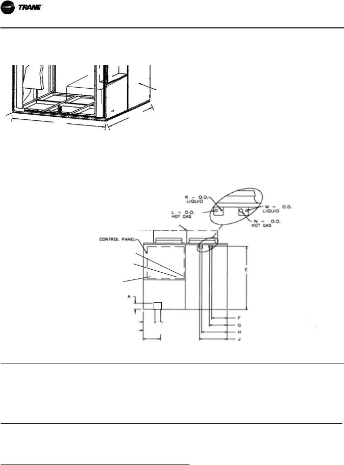
Figure 9. CCRC/CIRC air-cooled condenser
OPTIONAL LOW AMBIENT DAMPER (ONE DAMPER PER CIRCUIT)
REFRIGERANT
LINE
CONNECTIONS
FRONTAL VIEW
AC
REFRIGERANT CIRCUIT 2
REFRIGERANT CIRCUIT 1
OPTIONAL LOW
AMBIENT DAMPER
24VOLTWIRE ENTRY HOLE SIZED FOR 3/4” CONDUIT
115VOLTWIRE ENTRY HOLE SIZED FOR
3/4” CONDUIT
SUPPLYVOLTAGEWIRE ENTRY HOLE
SIZED FOR 1” CONDUIT
B
C
(LIQUID LINE CONNECTION REFRIG. CIRCUIT 1) (HOT GAS CONNECTION REFRIG. CIRCUIT 1)
(LIQUID LINE CONNECTION REFRIG. CIRCUIT 2) (HOT GAS CONNECTION REFRIG. CIRCUIT 2)
Table 9. CCRC/CIRC air-cooled condenser dimensions & weight, in-lbs.
Model |
AA |
AB |
AC |
shipping weight |
operating weight |
|
|
|
|
|
|
|
|
CCRC/CIRC 20 |
70 |
1/8 |
88 |
88 |
2030 |
1906 |
|
|
|
|
|
|
|
CCRC/CIRC 29 |
70 |
1/8 |
88 |
88 |
2084 |
1960 |
|
|
|
|
|
|
|
CCRC/CIRC 32 |
70 |
1/8 |
88 |
88 |
2138 |
2014 |
|
|
|
|
|
|
|
Table 10. CCRC/CIRC refrigerant connections, in.
Model |
E |
F |
G |
H |
J |
K |
L |
M |
N |
|
|
|
|
|
|
|
|
|
|
CCRC/CIRC 20-32 |
66 7/8 |
14 3/8 |
18 1/2 |
24 3/4 |
29 |
5/8 |
7/8 |
5/8 |
7/8 |
|
|
|
|
|
|
|
|
|
|
Table 11. CCRC/CIRC electrical connections, in.
Model |
A |
B |
C |
|
|
|
|
CCRC/CIRC 20-32 |
4 1/2 |
10 1/2 |
17 1/2 |
|
|
|
|
20 |
SCXG-SVX01H-EN |
Dimensions & Weights
Figure 10. Hot water coil: left-hand connections
Table 12. Hot water coil dimensions & weight, in-lbs
|
A |
B |
C |
D |
E |
F |
G |
H |
J |
K |
Weight |
|
|
|
|
|
|
|
|
|
|
|
|
one-row coil |
53 3/4 |
4 7/8 |
73 1/2 |
16 5/8 |
6 3/4 |
7 1/2 |
23 1/8 |
37 1/4 |
1 3/4 |
2 1/2 |
415 |
|
|
|
|
|
|
|
|
|
|
|
|
two-row coil |
53 3/4 |
5 1/8 |
73 1/2 |
16 5/8 |
6 3/4 |
7 1/2 |
22 3/8 |
37 1/4 |
2 3/4 |
3 5/8 |
510 |
|
|
|
|
|
|
|
|
|
|
|
|
Figure 11. Hot water coil: right-hand connections
SCXG-SVX01H-EN |
21 |
Dimensions & Weights
Figure 12. Steam coil: left connections
|
92 3/4" |
22 1/2" |
|
|
73 1/2" |
|
|
|
53 13/16" |
|
|
|
|
|
|
|
VERTICAL |
3 5/16" |
|
|
15 7/8" |
CONDENSER |
|
|
DISCHARGE |
1" |
FITTINGS |
|
|
1 1/2" NPTI |
|
|
|
|
|
30 7/8" |
3/4" (4X) ISOLATOR |
36 15/16" 40 15/16" |
ELECTRICAL |
MOUNTING LOCATION |
CONNECTIONS |
||
|
ON BOTTOM OF UNIT |
|
|
2 1/8" |
|
|
|
|
14 9/16" |
64 1/2" |
11" |
9 3/8" |
35" |
|
||||
|
|
|
|
|
|
|
|
|
|
|
|
Note: Steam Coil Weight 460 Lbs. |
3 7/8" |
|
|||
|
|
|
|
|
|
|
TOP VIEW |
6 3/4" |
|
|
|||
|
|
|
|
|
||
|
16 15/16" |
|
||||
LEFT VIEW
Figure 13. Steam coil: right connections
CONDENSATE RETURN TRAP |
VACUUM BREAKER 1" |
1 1/2" FEMALE CONN |
FEMALE CONN |
STEAM INLET 1"
FEMALE CONN VACUUM BREAKER 1"
FEMALE CONN
CONDENSATE RETURN TRAP 1" FEMALE CONN
|
92 3/4" |
|
|
|
|
73 1/2" |
VERTICAL |
22 1/2" |
|
|
|
DISCHARGE |
|
53 13/16" |
|
|
|
3 5/16" |
|
|
|
PIPING CONNECTIONS |
|
|
|
|
15 7/8" |
|
|
|
|
2 1/2" NPTE |
|
|
|
|
1" |
|
|
|
|
3/4" (4X) ISOLATOR |
|
|
|
|
MOUNTING LOCATION |
|
|
30 7/8" |
|
ON BOTTOM OF UNIT |
40 15/16" |
|
|
|
|
36 15/16" |
|
|
|
|
|
|
2 1/8" |
|
|
|
|
11" |
64 1/2" |
10 15/16" |
|
|
|
35" |
|
||
|
|
|
|
|
|
TOP VIEW |
|
3 7/8" |
|
|
Note: Steam Coil Weight 460 Lbs. |
9 3/8" |
|
|
|
|
|
6 3/4" |
|
|
|
|
16 15/16" |
|
RIGHT VIEW
22 |
SCXG-SVX01H-EN |
Dimensions & Weights
Figure 14. Electric Heat Coil
Table 13. Electric heat coil dimensions & weight, in-lbs.
Unit Size |
A |
B |
C |
D |
Weight |
|
|
|
|
|
|
|
|
20 tons |
70 1/4 |
4 7/8 |
11 1/2 |
19 |
460 |
|
|
|
|
|
|
|
|
25 tons |
70 1/4 |
4 1/8 |
11 1/2 |
19 |
460 |
|
|
|
|
|
|
|
|
30 - 35 |
70 1/4 |
2 7/8 |
11 1/2 |
19 |
460 |
|
tons |
||||||
|
|
|
|
|
Note: Coil box height is 8 in.
Figure 16. Waterside Economizer
Table 15. Waterside economizer weight, in-lbs.
|
|
Weight |
Unit size |
2-row |
4-row |
|
|
|
20 - 35 tons |
488 |
584 |
|
|
|
Figure 15. Flexible horizontal discharge plenum
Figure 17. Airside Economizer
Table 14. Flexible horizontal discharge plenum dimensions & weights, in-lbs.
20-35 tons |
A |
B |
C |
Weight |
|
|
|
|
|
Low height |
35 |
17 1/4 |
86 1/2 |
262 |
|
|
|
|
|
Standard height |
35 |
25 1/4 |
86 1/2 |
352 |
|
|
|
|
|
Table 16. Airside economizer dimensions & weight, in-lbs.
Unit Size |
A |
B |
C D |
E |
F (1) |
F (2) |
G (1) |
G (2) |
H (1) H (2) |
J |
K |
L |
M |
Weight |
|
|
|
|
|
|
|
|
|
|
|
|
|
|
|
|
|
SCWG/SIWG 20, 25 |
36 |
65 5/8 |
37 74 1/4 |
6 1/8 |
56 1/2 |
49 3/4 |
23 1/4 |
20 1/2 |
5 5/8 |
7 |
20 1/2 |
17 1/8 |
12 |
49 3/4 |
273 |
SCRG/SIRG 20 |
|
|
|
|
|
|
|
|
|
|
|
|
|
|
|
|
|
|
|
|
|
|
|
|
|
|
|
|
|
|
|
SCWG/SIWG 30, 35 |
36 |
65 5/8 |
37 74 1/4 |
6 1/8 |
61 3/8 |
62 3/4 |
28 1/8 |
20 1/2 |
3 1/4 |
7 |
20 1/2 |
17 1/8 |
5 1/2 |
62 3/4 |
273 |
SCRG/SIRG 25, 32 |
|
|
|
|
|
|
|
|
|
|
|
|
|
|
|
|
|
|
|
|
|
|
|
|
|
|
|
|
|
|
|
SCXG-SVX01H-EN |
23 |
Dimensions & Weights
Service Clearances
Figure 18. Detail “B” (top) and Detail “A” (bottom)
See Figure 19, p. 24 and Figure 20, p. 24 for recommended service and code clearances.
Figure 19. Top view CCRC/CIRC 20, 29, 32
96” (2132 mm)
48” |
48” |
(1066 mm) |
(1066 mm) |
Control
Panel
96” (2132 mm)
Table 17. Service and code clearance requirements
Side |
Distance |
Purpose |
|
|
|
front |
42 in. |
NEC code requirement |
(20-38 tons) |
||
|
|
|
|
18 in. |
air-cooled units only |
left |
36 in. |
refrigeration & waterside component service |
|
77 in. |
fan shaft removal |
|
|
|
right |
36 in. |
provides uniform airflow |
|
|
|
inlet |
18 in. |
provides uniform airflow |
|
|
|
Table 18. Service and code clearance requirements
Side |
Distance |
Purpose |
|
|
|
front |
42 in. |
NEC code requirement |
(20-38 tons) |
||
|
|
|
|
18 in. |
air-cooled units only |
left |
36 in. |
refrigeration & waterside component service |
|
77 in. |
fan shaft removal |
|
|
|
right |
36 in. |
provides uniform airflow |
|
|
|
inlet |
18 in. |
provides uniform airflow |
|
|
|
Note: When unit is ordered with horizontal supply, ensure that all applicable codes are considered when installing equipment. Special attention should be made to overhead clearances of unit/ ducting to meet code requirements.
Figure 20. Top view of self-contained unit showing recommended service and code clearances
air inlet |
18” minimum |
See |
36” |
table |
minimum |
|
42” minimum |
Control Panel |
|
24 |
SCXG-SVX01H-EN |
Installation - Mechanical
Unit Handling Procedures
 WARNING
Improper Unit Lift!
Test lift unit approximately 24 inches to verify proper center of gravity lift point. To avoid dropping of unit, reposition lifting point if unit is not level. Failure to properly lift unit could result in unit dropping and possibly crushing operator/technician which could result in death or serious injury and possible equipment or property-only damage.
WARNING
Heavy Objects!
Ensure that all the lifting equipment used is properly rated for the weight of the unit being lifted. Each of the cables (chains or slings), hooks, and shackles used to lift the unit must be capable of supporting the entire weight of the unit. Lifting cables (chains or slings) may not be of the same length. Adjust as necessary for even unit lift. Other lifting arrangements could cause equipment or property damage. Failure to follow instructions above or properly lift unit could result in unit dropping and possibly crushing operator/ technician which could result in death or serious injury.
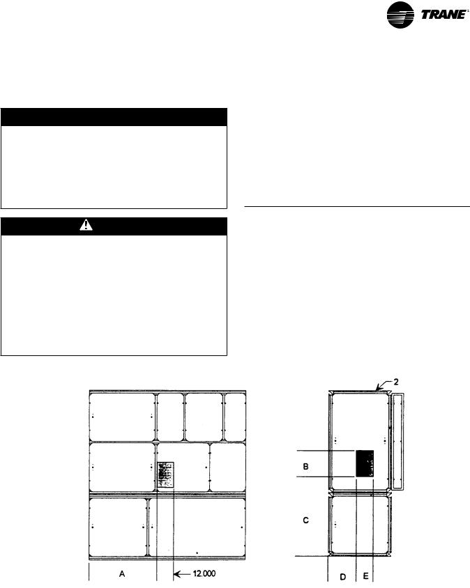
Figure 21. Assembled unit gravity block location
Before lifting the unit or modular component, determine the approximate center of gravity for lifting safety. See Figure 21, p. 25 for assembled modular units and Figure 22, p. 26 for split-apart units.The center of gravity may vary slightly within the gravity block depending on unit options.
Always test-lift the unit to determine the exact unit balance and stability before hoisting it to the installation location. See Figure 23, p. 26 and Figure 24, p. 27 for typical rigging procedures and proper rigging equipment usage.
Table 19. Gravity block dimensions
Model |
A |
B |
C |
D |
|
|
|
|
|
SCWG |
36 |
14 |
38 |
12 |
SCRG |
36 |
16 |
40 |
12 |
|
|
|
|
|
SCXG-SVX01H-EN |
25 |
Installation - Mechanical
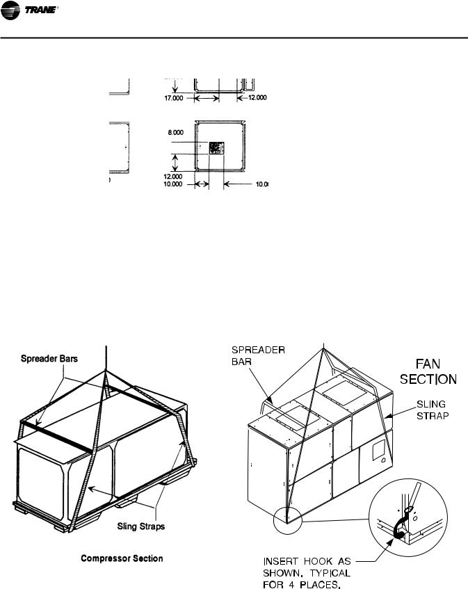
Figure 22. Split-apart unit gravity block location
Fan Section Only
Compressor Section Only
Figure 23. Split-apart modular unit proper rigging (L) and fan section (R)
26 |
SCXG-SVX01H-EN |
Installation - Mechanical
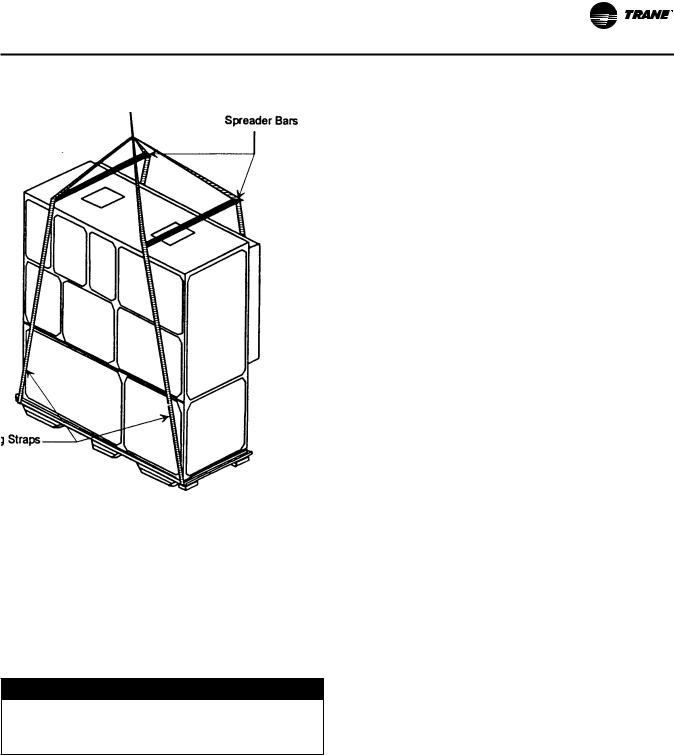
Figure 24. Assembled modular unit proper rigging
Skid Removal
The unit ships on skids to provide forklift locations from the front or rear.The skid allows easy maneuverability of the unit during storage and transportation. Remove the skids before placing the unit in its permanent location.
Remove the skids using a forklift or jack. Lift one end of the unit off of the skids. See Figure 21, p. 25 and Figure 22, p. 26 for unit gravity block location. Slide the skids out and lower the unit at the installation location.
NOTICE:
Equipment Damage!
Do not use hooks to lift unit or hook into open channels to lift unit.This could cause unit damage
1.Position rigging sling under wood shipping skid.
2.Use spreader bars to avoid unit damage.
3.When using a forklift, exercise caution to prevent unit damage.
4.Use the standard fork length to lift one end and drag or pull unit while skidding the opposite end.
5.The unit center of gravity will fall within center of gravity block at various locations depending on unit options.
6.Use hooks to lift fan section only. Do not hook into open channels to lift unit.
7.See unit nameplate for unit weight.
8.Do not stack units.
Installation Preparation
Important: Before installing the unit, perform the following procedures to ensure proper unit operation.
Before installing the unit, perform the following procedures to ensure proper unit operation.
1.Position the unit and skid assembly in its final location. If unit shipped split-apart, follow the procedure in the “Split-Apart Unit Assembly,” p. 28 before completing this step.Test lift the unit to determine exact unit balance and stability before hoisting it to the installation location. See Figure 23, p. 26 and
Figure 24, p. 27 for typical rigging procedures, including cautions and proper uses of such equipment as fork lifts, spreader bars, and hooks.
2.Test lift the unit to determine exact unit balance and stability before hoisting it to the installation location. See “Unit Handling Procedures,” p. 25 for proper rigging procedures and cautions.
3.Remove the skids from under the unit. See “Skid Removal,” p. 27.
4.Remove the protective shipping covers from the unit.
5.Verify isolators are properly tightened for operation. See “Unit Vibration Isolator Option,” p. 29.
Note: Unit height and connection locations will change if external vibration isolators are used.The unit may be raised an additional 5-7/8 inches with springtype isolators.
Note: Unit height and connection locations will change if the unit is constructed to be split-a-part in the field. See unit submittal drawings for connection locations.
6.Tighten compressor isolator mounting bolts.Torque to 18 ft. lbs. (± 2 ft. Lbs.)
7.Electrical supply power must meet specific balance and voltage requirements, as described in section “Installation - Electrical,” p. 39.
8.Water-cooled units only (model SCWG):The installer must furnish and install a condenser main and standby water pump, cooling tower, pressure gauges and all components for the waterside piping. See “General Waterside Recommendations: CoolingTowers,” p. 32.
9.Air-cooled units only (model SCRG):These units require field-installation of a remote air-cooled condenser and refrigerant piping. See “Refrigerant System,” p. 36.
SCXG-SVX01H-EN |
27 |
Installation - Mechanical
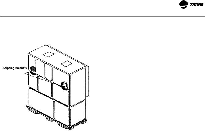
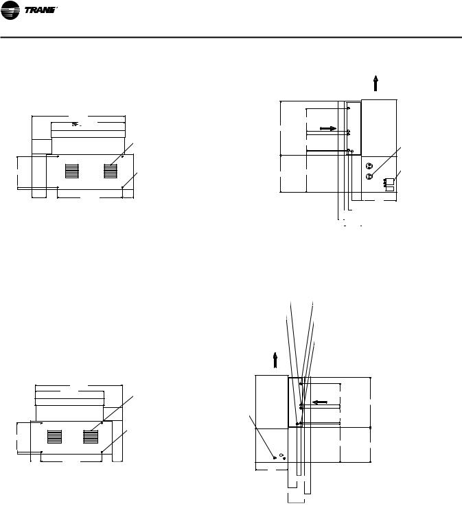
Split-Apart Unit Assembly
1.Ensure the tagging information on the fan section nameplate matches that on the compressor nameplate.
2.Remove the connector brackets holding the sheet metal shipping cover on compressor section. Retain brackets and screws.
3.Remove shipping cover from the compressor section and verify the ship-with package contains:
a.suction and liquid line couplings
b.insulation
c.sheet metal screws
4.Lift fan section onto the compressor section using the rigging method in Figure 23, p. 26.
5.Remove skid from the fan section, placing the fan section onto the compressor section. Reference Figure 26, p. 29.
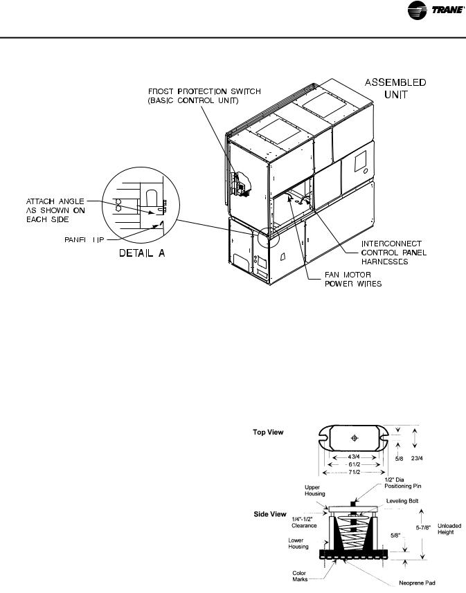
6.Install the connection brackets with the sheet metal screws (referenced in step 2) on all sides of the unit. Reference Detail “A” in Figure 26, p. 29.
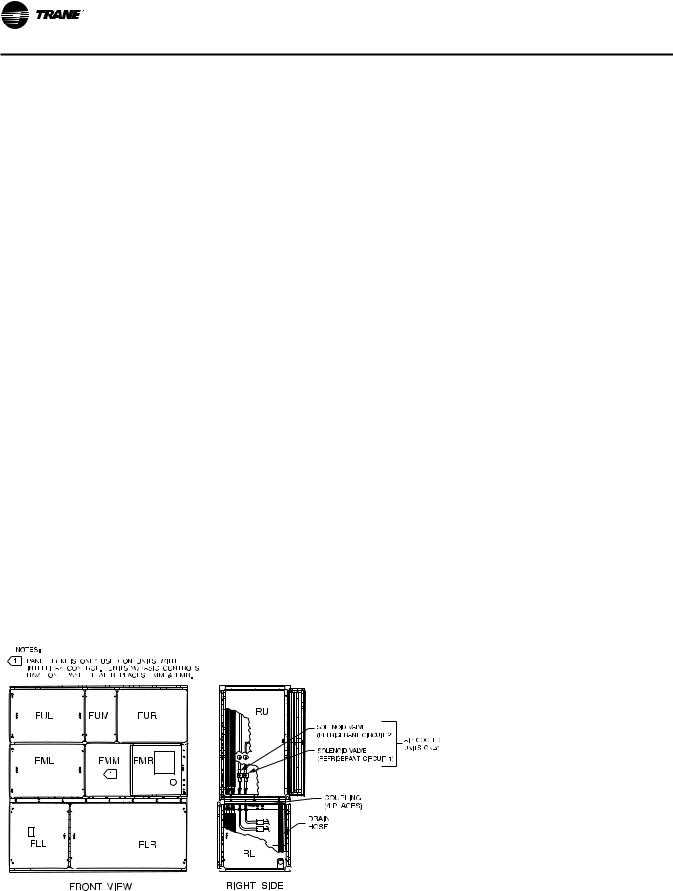
7.Remove the unit panels labeled RU and RL in Figure 25,
p.28. To remove panels, first remove the four shipping screws located in the corner of each panel. Next, turn the remaining 1/4 turn fasteners to the unlatch position.The panel is supported by a “lip” channel. So, lift the panel up and off the unit to remove it. See Detail “A” in Figure 26, p. 29.
8.Connect the drain hose to the drainpan outlet fitting and secure it with the drain hose clamp provided.
9.See “Refrigerant System,” p. 36 for piping procedures.
10.Remove panel FLR and open the bottom control panel door, FLL. Pull the fan motor leads (coiled in the fan
section) through the knockout in the bottom of the fan section to the control panel. Ensure that the bushing is installed in the hole to prevent the wires from chafing. Refer to the unit wiring diagrams to connect the fan motor leads properly and ensure correct phase sequencing.
IntelliPak Units (UCM) Only
11.Remove panels FML, FMM, and FMR.
12.Pull the circular plug connector (CPC) from the compressor section through the knockouts into the fan section. Install the bushings (provided on the wiring harnesses) in the knockouts.\
13.Using the CPC wiring diagram, connect the male CPC to the female CPC in the top control panel.
14.If the unit has the mixed air temperature option, route the capillary tube on back of the filter rack.
Units with Thermostat Only
15.Remove panel FMR. See Note 1 on Figure 25, p. 28.
16.Pull frost protection wires from the bottom control panel through knockouts in bottom of fan section. Route wires to the appropriate frost protection switches on the evaporator coil. Reference the unit wiring diagrams to connect frost protection wiring connectors.
Air-Cooled Units Only
17.Route the refrigerant circuit wires for circuits 1 and 2 from the bottom control panel through the knockouts to the solenoid valves.The solenoid valves are located in the liquid refrigerant lines on the right-hand side of the unit. Refer to the unit wiring diagrams to make splice connections.
Figure 25. Modular unit panel description and internal connections
28 |
SCXG-SVX01H-EN |
Installation - Mechanical
Figure 26. How to assemble the modular unit
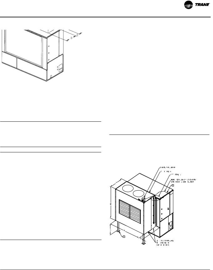
Unit Vibration Isolator Option
If your job requires external vibration isolation, two options are available: isopads or spring-type isolators. Isopads should be placed under the unit at locations indicated on the factory-provided isolator sheet.
Set the spring-type isolators (Figure 27, p. 29) in position after the unit is removed from skids before making electrical, piping, or duct connections. All units require a minimum of four isolators per unit. But some may require six isolators, depending upon unit options.
Note: Trane strongly recommends you consult a vibration specialist before double-isolating the unit. Double isolation is not recommended.
If you decide to externally isolate the unit, use spring-flex, type CP isolators.The spring number is marked on the outer housing. See Figure 27, p. 29.
To install external isolators, complete the following procedure.
1.Locate the isolators under unit base at the locations indicated on the factory-provided isolator placement sheet. Lift one end of the unit at a time to position isolators to the floor, using anchor bolts.
2.Level the unit by adjusting isolator heights. Unit weight may cause the upper housing to rest on the lower housing of the spring isolators.The isolator clearance shown in the side view of Figure 27, p. 29, must be 1/4 - 1/2 inches.To increase the clearance, lift the unit off the isolator and turn the leveling bolt counterclockwise. Recheck the unit level and the housing clearances. Maximum allowable difference
between isolator heights is 1/4 inch. Shim as required under the isolators.
Note: The compressors and fan assembly are internally isolated on most units. Due to this, the addition of external isolation devices (spring mounting isolators) is at the discretion of the building or HVAC system designer.
Figure 27. Optional spring isolator dimensional data
SCXG-SVX01H-EN |
29 |
Installation - Mechanical
Duct Connections
 WARNING
Hazardous Voltage w/Capacitors!
Disconnect all electric power, including remote disconnects and discharge all motor start/run capacitors before servicing. Follow proper lockout/ tagout procedures to ensure the power cannot be inadvertently energized. For variable frequency drives or other energy storing components provided by Trane or others, refer to the appropriate manufacturer’s literature for allowable waiting periods for discharge of capacitors. Verify with an appropriate voltmeter that all capacitors have discharged. Failure to disconnect power and discharge capacitors before servicing could result in death or serious injury.
For additional information regarding the safe discharge of capacitors, see PROD-SVB06A-EN
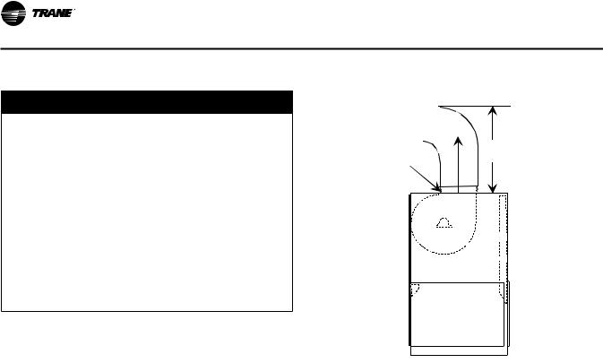
Return air enters the rear of the unit and conditioned supply air discharges through the top. Attach supply air ductwork directly to the unit’s top panel, around the fan discharge opening. A duct collar is not provided.
Note: Units equipped with the flexible horizontal discharge plenum option may include a duct collar when holes are factory cut. If discharge openings are field-cut, refer to the “Plenum Installation” section.
Install all air ducts according to the National Fire Protection Association standards for the “Installation of Air Conditioning and Ventilation Systems other than ResidenceType (NFPA 90A) and ResidenceType Warm Air Heating and Air Conditioning Systems (NFPA 90B).
Make duct connections to the unit with a flexible material such as heavy canvas. If a fire hazard exists,Trane recommends using Flexweave 1000, type FW30 or equivalent canvas. Use three inches for the return duct and three inches for the discharge duct. Keep the material loose to absorb fan vibration.
Note: The compressors and fan assembly are internally isolated.Therefore, external isolation devices (spring mounting isolators) are at the discretion of a vibration specialist consulted by the building or HVAC system designer.
Figure 28. Duct connection recommendations
Discharge
Duct
3 Fan
3-inch Diameters
Flexible
Duct
 Return
 Air
Air
Run the ductwork straight from the opening for a minimum of three fan diameters. See Figure 28, p. 30. Extend remaining ductwork as far as possible without changing size or direction. Do not make abrupt turns or transitions near the unit due to increased noise and excessive static losses. Use elbows with splitters or turning vanes to minimize static losses.
Poorly constructed turning vanes may cause airflow generated noise. Align the fan outlet properly with the ductwork to decrease noise levels in the duct and to increase fan performance. To complete trunk ductwork to the VAV terminal units, refer to the VAV box manuals for specific requirements. Check total external static pressures against fan characteristics to be sure the required airflow is available throughout the ductwork.
To achieve maximum acoustical performance, minimize the duct static pressure setpoint
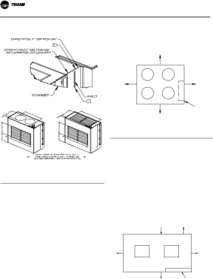
Plenum
Before installing the plenum attach the insulation strip that ships with the plenum. See Figure 29, p. 31 for proper insulation location. Align the plenum front with the control panel side of the unit. Using the strips and screws provided, secure the plenum to the unit.
Treat field-cut holes to prevent fiberglass from entering the airstream.
Note: Plenum insulation must be applied properly to prevent air bypass around the plenum. See Figure 29, p. 31.
30 |
SCXG-SVX01H-EN |
Loading...