


Installation Manual
NEW STYLUS TM
Split System, 1-5 Tons
Convertible Type
MCX Series 50/60 Hz
50 Hz Models Cooling Only
MCX 512 GB MCX 518 GB MCX 524 GB MCX 530 GB MCX 536 GB MCX 042 GB MCX 048 GB MCX 060 GB
60 Hz Models Cooling Only
MCX 512 G1 MCX 518 G1 MCX 524 G1 MCX 530 G1 MCX 536 G1 MCX 042 G1 MCX 048 G1 MCX 060 G1
July 2007 |
MS-SVN015-EN |
MS-SVN015-EN.p65 |
1 |
6/27/07, 11:23 AM |
Black
General Information
General Information
This Installation Manual is given as a guide to good practice in the installation by the installer of MCX mini-split system. Installation procedures should be performed in the sequence that they appear in this manual.
For installing the unit to operate properly and reliably, it must be installed in accordance with these instructions. Also, the services of a qualified service technician should be employed, through the maintenance contract with a reputable service company.
Read these Installation Instructions completely before installing the air conditioning system.
About the Unit
These MCX units are assembled, pressure tested, dehydrated, charged and run tested before shipment. The information contained in this manual applies to MCX units are designed to operate in cooling mode only and in cooling or heating modes.
Trane MCX series of mini-split systems offer three styles of installation: floor, low wall and under ceiling with both LCD wireless remote control or wired control. Trane MCX series provide flexibility and savings.
Note: For model MCX 042, MCX 048 and MCX 060, there are only two styles of installation: under ceiling and low wall.
About this Manual
Cautions appear at appropriate places in this Instruction Manual. Your personal safety and the proper operation of this machine require that you follow them carefully. The Trane Company assumes no liability for installations or servicing performed by unqualified personnel. All phases of the installation of this air conditioning system must conform to all national, provincial, state and local codes.
Reception
On arrival, inspect the unit before signing the delivery note. Specify any damage of the unit on the delivery note, and send a registered letter of protest to the last carrier of the goods within 72 hours of delivery. Notify the dealer at the same time.
The unit should be totally inspected within 7 days of delivery. If any concealed damage is discovered, send a registered letter of protest to the carrier within 7 days of delivery and notify the dealer.
Warning
Warnings are provided at appropriate places in this manual to indicate to installers, operators and service personnel of potentially hazardous situations which, if not avoided, COULD result in death or serious injury.
© American Standard Inc. 2005
MS-SVN015-EN.p65 |
2 |
Black
Caution
Cautions are provided at appropriate places in this manual to indicate to installers, operators, and service personnel of potentially hazardous situations which, if not avoided, MAY result in minor or moderate injury or malfunction of the unit.
Warranty
Warranty is based on the general terms and conditions by country. The warranty is void if the equipment is modified or repaired without the written approval of The Trane Company, if the operating limits are exceeded or if the control system or the electrical wiring is modified.
Damage due to inappropriate installation, lack of knowledge or failure to comply with the manufacturer’s instructions, is not covered by the warranty obligation. If the installation does not conform to the rules described in Installation Manual, it may entail cancellation of warranty and liabilities by The Trane Company.
Important
This document is customer property and is to remain with unit. Please place in service information pack upon completion of work. These instructions do not cover all variations in systems, nor do they provide for every possible contingency to be met in connection with installation. Should further information be desired or should particular problems arise which are not covered sufficiently in this manual, the matter should be referred to your authorized Trane dealer.
MS-SVN015-EN
6/27/07, 11:23 AM
Contents
General Information |
2 |
|
Typical Installation |
|
|
|
4 |
|
Location and Preparation of Units |
|
|
5 |
||
Unit Installation |
|
|
|
6 |
|
Connection of Refrigerant Tubing |
|
|
7 |
||
Condensate Drain Piping |
|
|
|
9 |
|
Electrical Installation |
|
|
|
10 |
|
Remote Control Installation |
|
|
11 |
||
Typical Wiring Diagram |
|
|
|
12 |
|
Dimensional Data |
|
|
16 |
||
Notes |
|
|
18 |
||
MS-SVN015-EN |
|
3 |
MS-SVN015-EN.p65 |
3 |
6/27/07, 11:59 AM |
|
Black |
|

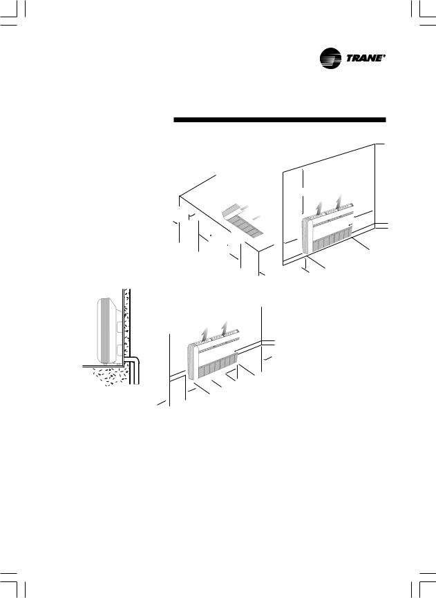
Typical Installation
Return air grille |
Supply air grille |
contains air filter |
Adjustable louvers direct air |
Ceiling mounted
Indoor unit
Refrigerant tubing/wiring
Supply air grille
Adjustable louvers direct air
Outdoor unit
 Drain
Drain
Return air grille contains air filter
Floor mounted
Low wall mounted
Note: For models MCX 042, MCX 048, MCX 060
there are only two styles of installation: under ceiling and low wall
4 |
|
MS-SVN015-EN |
MS-SVN015-EN.p65 |
4 |
6/27/07, 11:23 AM |
|
Black |
|
Location and Preparation of Units
1.Select an appropriate position that allows every corners of the room to be uniformly air conditioned and where it is easy to route the refrigerant tubing.
2.Ensure that the floor or ceiling construction is sufficient to fully support the weight of the indoor unit.
3.Consideration must be given to assure an unobstructed flow of supply and return air.
4.Refrigerant tubes between indoor and outdoor units should be as short as possible.
5.Length of the condensate drain hose should be kept as short as possible (Figure 1).
6.Recommended service clearance as shown in figure 2, 3 and 4.
Min. 20 cm.
Min. |
|
|
|
||
20 |
cm. |
|
|
|
|
|
|
|
|
|
|
Maintenance area |
|
Min. |
|||
|
|||||
|
|||||
(Celling mounted) |
|
||||
|
|
|
30 |
cm. |
|
|
|
|
|
|
|
Figure 2
|
|
|
|
Min |
. |
|
|
|
|
|
. |
||
|
|
|
|
|
|
|
|
|
|
|
30 |
cm |
|
|
|
|
|
|
|
|
|
|
|
|
area |
|
|
Figure 1 |
Min |
. |
mounted) |
|
|
|
|
cm. |
|
|
|||
20 |
Maintenance |
|
|
|||
|
|
|
(Floor |
|
|
|
Figure 3
Min. 120 cm.
Min |
. |
||
. |
|||
|
|
||
30 |
cm |
||
|
|
||
Min |
. |
. |
||
20 |
cm |
|||
|
||||
|
|
|
||
area Maintenancewall mounted)
(Low
Min. 20 cm.
Figure 4
7.Do not install unit in direct sunlight or near other heat sources as this may affect performance. Do not allow outside air to directly enter unit or condensate may form at the unit’s discharge.
Note: For MCX042-MCX060 the unit should be installed over the floor at least 20 cm.
MS-SVN015-EN |
|
5 |
MS-SVN015-EN.p65 |
5 |
6/27/07, 11:23 AM |
|
Black |
|
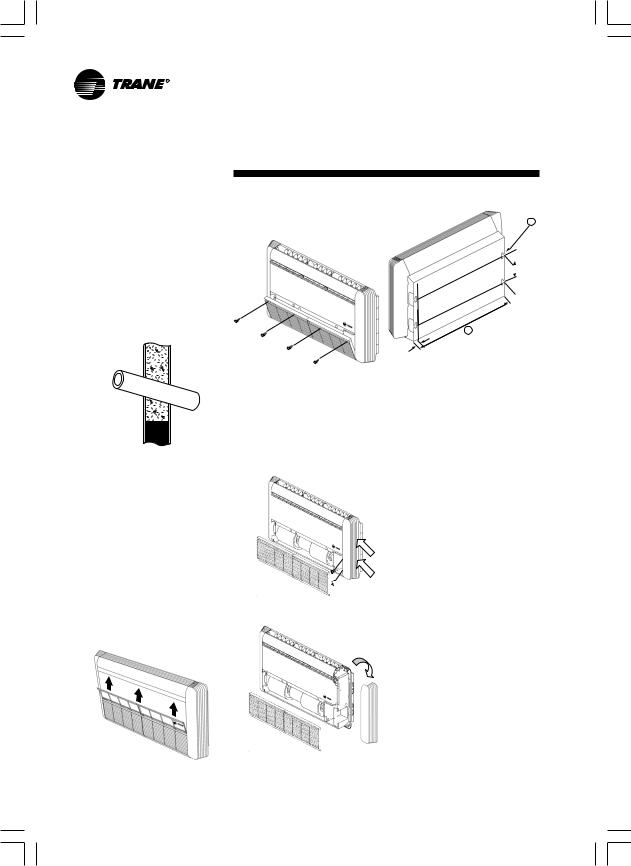
Unit Installation
Indoor Unit |
6. Unscrew at the return grille |
|
(Figure 7). |
1.Select a location to route tubing, wiring and drain pipe between the indoor and outdoor units.
2.Make a hole in the wall using a key hole saw or hole-cutting drill attachment.
The hole should be made at a slight downward slant to the outdoor side (Figure 5).
Outdoor side
Indoor side
Figure 5
Figure 7
7.Unscrew at the grille bottom hinges, pull out the screw, and unscrew at the side panel front (Figure 8). Then, push down on the side panel front and pull up (Figure 9).
Before cutting, check that no pipes or studs are directly behind the place to be cut. Avoid areas where electrical wiring or conduits are located.
3. |
Place the unit on a solid and level |
|
|
foundation. |
|
4. |
Tubing, wiring through and drain |
|
|
pipe of low wall and floor |
|
|
mounted units can be routed, |
|
|
rear or right side of unit when |
|
|
facing front. |
Figure 8 |
|
Ceiling mounted can be routed |
|
|
|
|
|
straight downward. |
|
5. |
Pull air filters upward (Figure 6). |
|
Pull
Pull
Figure 9
Figure 6
A
 8.5"(215)
0.83"(21)
B
0.83"(21)
Figure 10
Note: = A 0.49" x 1.575" - 4 SLOT (Mounting hole) (12.5 mm 40.0 mm)
Unit Size |
B |
MCX 512-518 |
36.2" (920) |
MCX 524 |
46.1" (1,170) |
MCX 530-536 |
55.9" (1,420) |
MCX 042-048 |
65.7" (1,670) |
MCX 060 |
75.6" (1,920) |
8.Place or hang the unit at the selected position.
9.Replace both right and left side panels, and the return grille after the installation of wiring, tubing and piping is complete.
Outdoor Unit
See the proper installation method provided in the Installation Manual for the outdoor unit.
6 |
|
MS-SVN015-EN |
MS-SVN015-EN.p65 |
6 |
6/27/07, 11:23 AM |
|
Black |
|
 Loading...