


®
|
Installation |
RT-SVX10C-EN |
|
Operation |
|
|
Maintenance |
|
|
|
|
|
Library |
Service Literature |
|
|
|
|
Product Section |
Unitary |
|
|
|
|
Product |
Rooftop Air Conditioning (Comm. SZ, 20 - 130 Tons) |
|
|
|
|
Model |
SAH_, SEH_, SFH_, SLH_, SSH_, SXH_ |
|
|
|
|
Literature Type |
Installation/Operation/Maintenance |
|
|
|
|
Sequence |
10C |
|
|
|
|
Date |
January 2005 |
|
|
|
|
File No. |
SV-UN-RT-RT-SVX10C-EN-01-05 |
|
|
|
|
Supersedes |
RT-SVX10C-EN 11/04 |
|
|
|
INTELLIPAK™ |
|
|
Commercial Single-Zone Rooftop Air |
|
|
Conditioners with CV or VAV Controls |
|
|
Models
"5" and later Design Sequence
SAHF -C20, -C25, -C30, -C40, -C50, -C55, -C60, -C70, -C75 SEHF -C20, -C25, -C30, -C40, -C50, -C55, -C60, -C70, -C75 SFHF -C20, -C25, -C30, -C40, -C50, -C55, -C60, -C70, -C75 SLHF -C20, -C25, -C30, -C40, -C50, -C55, -C60, -C70, -C75 SSHF -C20, -C25, -C30, -C40, -C50, -C55, -C60, -C70, -C75 SXHF -C20, -C25, -C30, -C40, -C50, -C55, -C60, -C70, -C75
"X" and later Design Sequence
SXHG -C90, -D11, -D12, -D13 SEHG -C90, -D11, -D12, -D13 SFHG -C90, -D11, -D12, -D13 SLHG -C90, -D11, -D12, -D13 SSHG -C90, -D11, -D12, -D13
With 3-DTM Scroll Compressors
© 2004 American Standard Inc. All rights reserved
- Units whose model numbers have a "1" in digit 20 are certified by Underwriters Labortory.
- Units whose model numbers have a "2" in digit 20 are certified by the Canadian Standards Association (CSA).
Trane has a policy of continuous product and product data improvement and reserves the right to change design and specifications without notice. Only qualified technicians should perform the installation and servicing of equipment referred to in this publication.

Note: This document is customer property and must be retained by the unit's owner for use by maintenance personnel.
Literature Change History
RT-SVX10C-EN (November 2004)
Re-issue of manual for minor corrections to Connection Sizes Table 3-5; provides specific installation, operation and maintenance instructions for S_HF with “6” and later design sequence and S_HG with “Y” and later design sequence with constant volume (CV) or variable air volume (VAV) controls.
RT-SVX10C-EN (October 2004)
Re-issue of manual for minor corrections to warranty and updated sensor numbers (BAYSENS019, 20); provides specific installation, operation and maintenance instructions for S_HF with “6” and later design sequence and S_HG with “Y” and later design sequence with constant volume (CV) or variable air volume (VAV) controls.
RT-SVX10C-EN (July 2004)
Re-issue of manual for minor WARNING and CAUTIONS and Warranty information updates; provides specific installation, operation and maintenance instructions for S_HF with “6” and later design sequence and S_HG with “Y” and later design sequence with constant volume (CV) or variable air volume (VAV) controls.
RT-SVX10C-EN (December 2003)
Re-issue of manual for minor changes to programming parameters; provides specific installation, operation and maintenance instructions for S_HF with “6” and later design sequence and S_HG with “Y” and later design sequence with constant volume (CV) or variable air volume (VAV) controls.
About The Manual
RT-SVX10B-EN (October 2003)
Updated issue of this manual; provides specific installation, operation and maintenance instructions for S_HF with “6” and later design sequence and S_HG with “Y” and later design sequence with constant volume (CV) or variable air volume (VAV) controls.
RT-SVX10A-EN (May 2003)
Updated issue of this manual; provides specific installation, operation and maintenance instructions for S_HF with “5” and later design sequence and S_HG with “X” and later design sequence with constant volume (CV) or variable air volume (VAV) controls.
SXH_-IOM-9 (November 2002)
Re-issue of manual for minor clarity issues; provides specific installation, operation and maintenance instructions for “3” and later design sequence on S_HF units and "W" and later design sequence on S_HG units with constant volume (CV) or variable air volume (VAV) controls.
SXH_-IOM-9 (June 2002)
Original issue of manual; provides specific installation, operation and maintenance instructions for “3” and later design sequence on S_HF units and "W" and later design sequence on S_HG units with constant volume (CV) or variable air volume (VAV) controls.
These units are equipped with electronic Unit Control Modules (UCM) which provides operating functions that are significantly different than conventional units. Refer to the "StartUp" and "Test Mode" procedures within this Installation, Operation, & Maintenance manual and the latest edition of the appropriate programming manual for CV or VAV applications before attempting to operate or service this equipment.
Note: The procedures discussed in this manual should only be performed by qualified, experienced HVAC technicians.
Overview of Manual
This booklet describes proper installation, start-up, operation, and maintenance procedures for 20 through 130 Ton rooftop air conditioners designed for Constant Volume (CV) and Variable Air Volume (VAV) applications. By carefully reviewing the information within this manual and following the instructions, the risk of improper operation and/or component damage will be minimized.
Note: One copy of the appropriate service literature ships inside the control panel of each unit.
It is important that periodic maintenance be performed to help assure trouble free operation. Should equipment failure occur, contact a qualified service organization with qualified, experienced HVAC technicians to properly diagnose and repair this equipment.
Note: Do Not release refrigerant to the atmosphere!
If adding or removing refrigerant is required, the service technician must comply with all federal, state, and local laws.
2

Section One |
|
About The Manual ............................................................... |
2 |
Literature Change History ................................................ |
2 |
Overview of Manual ......................................................... |
2 |
Section Two |
|
General Information ............................................................. |
4 |
Model Number Description .............................................. |
4 |
Hazard Identification ........................................................ |
6 |
Commonly Used Acronyms ............................................. |
6 |
Unit Description ................................................................ |
6 |
Input Devices & System Functions .................................. |
8 |
Constant Volume & Variable Air Volume Units ................ |
8 |
Constant Volume (CV) Units .......................................... |
10 |
Variable Air Volume (VAV) Units .................................... |
11 |
Space Temperature Averaging ....................................... |
12 |
Unit Control Modules (UCM) .......................................... |
12 |
Section Three |
|
Installation .......................................................................... |
14 |
Unit Inspection ............................................................... |
14 |
Storage ........................................................................... |
14 |
Unit Clearances ............................................................. |
14 |
Unit Dimensions & Weight Information .......................... |
14 |
Roof Curb and Ductwork ............................................... |
22 |
Pitch Pocket Location .................................................... |
23 |
Unit Rigging & Placement .............................................. |
23 |
General Unit Requirements ........................................... |
25 |
Main Electrical Power Requirements ............................. |
25 |
Field Installed Control Wiring ......................................... |
25 |
Requirements for Electric Heat Units ............................ |
25 |
Requirements for Gas Heat ........................................... |
25 |
Requirements for Hot Water Heat (SLH_) ..................... |
25 |
Requirements for Steam Heat (SSH_) .......................... |
26 |
O/A Pressure Sensor and Tubing Installation ............... |
26 |
Condensate Drain Connection ....................................... |
27 |
Shipping Fasteners ........................................................ |
27 |
O/A Sensor & Tubing Installation ................................... |
31 |
Units with Statitrac™; .................................................... |
31 |
Gas Heat Units (SFH_) .................................................. |
32 |
Connecting the Gas Supply Line to the Furnace |
|
Gas Train ........................................................................ |
32 |
Flue Assembly Installation ............................................. |
34 |
Hot Water Heat Units (SLH_) ........................................ |
34 |
Steam Heat Units (SSH_) .............................................. |
35 |
Disconnect Switch External Handle ............................... |
38 |
Electric Heat Units (SEH_) ............................................ |
38 |
Main Unit Power Wiring ................................................. |
38 |
Disconnect Switch Sizing (DSS) .................................... |
44 |
Field Installed Control Wiring ......................................... |
45 |
Controls using 24 VAC ................................................... |
45 |
Controls using DC Analog Input/Outputs ....................... |
45 |
Constant Volume System Controls ................................ |
45 |
Variable Air Volume System Controls ............................ |
46 |
Constant Volume or Variable Air Volume System |
|
Controls .......................................................................... |
46 |
Table of Contents |
|
Section Four |
|
Unit Start-Up ...................................................................... |
55 |
Cooling Sequence of Operation .................................... |
55 |
Gas Heating Sequence of Operation ............................. |
56 |
Fenwal Ignition System .................................................. |
56 |
Honeywell Ignition System ............................................. |
56 |
Modulating Gas Sequence of Operation ....................... |
57 |
Flame Failure ................................................................. |
57 |
Electric Heat Sequence of Operation ............................ |
58 |
Wet Heat Sequence of Operation .................................. |
58 |
Electrical Phasing .......................................................... |
59 |
Voltage Supply and Voltage Imbalance ......................... |
60 |
Service Test Guide for Component Operation ............... |
61 |
Verifying Proper Fan Rotation ....................................... |
63 |
If all of the fans are rotating backwards;........................ |
63 |
System Airflow Measurements ...................................... |
63 |
Constant Volume Systems ............................................. |
63 |
Variable Air Volume Systems ......................................... |
65 |
Exhaust Airflow Measurement ....................................... |
66 |
TraqTM Sensor Airflow Measurement ............................ |
66 |
Economizer Damper Adjustment ................................. |
80 |
Compressor Start-Up ................................................... |
82 |
Compressor Operational Sounds ................................ |
83 |
Thermostatic Expansion Valves ................................... |
93 |
Charging by Subcooling .............................................. |
93 |
Low Ambient Dampers ................................................. |
93 |
Electric, Steam and Hot Water Start-Up ...................... |
94 |
Gas Furnace Start-Up .................................................. |
94 |
Two Stage Gas Furnace ............................................... |
95 |
Full Modulating Gas Furnace ....................................... |
97 |
Limited Modulating Gas Furnace ................................ |
98 |
Final Unit Checkout ...................................................... |
99 |
Section Five |
|
Service & Maintenance.................................................... |
100 |
Fan Belt Adjustment ..................................................... |
104 |
Scroll Compressor Replacement ................................. |
105 |
VFD Programming Parameters ................................... |
106 |
Monthly Maintenance ................................................... |
107 |
Filters............................................................................ |
107 |
Cooling Season ............................................................ |
107 |
Heating Season ............................................................ |
108 |
Coil Cleaning ................................................................ |
108 |
Final Process .............................................................. |
109 |
Index ........................................................................... |
111 |
Warranty ..................................................................... |
114 |
3

General Information
Model Number Description
All products are identified by a multiple character model number listed on the unit nameplate. An explanation of the alphanumeric identification code is provided below. Its use can define the unit's specific components, type of application, i.e. CV or VAV, for a particular unit.
When ordering replacement parts or requesting service, be sure to refer to the specific model number, serial number, and DL number (if applicable) stamped on the unit nameplate.
Sample Model No.: |
S X H F - C20 4 0 |
A |
1 0 |
A |
1 |
5 |
B |
1 |
D |
0 |
1 |
A,R,L,etc. |
Digit No.: |
1 2 3 4 5,6,7 8 9 |
10 |
11 12 |
13 |
14 |
15 |
16 |
17 |
18 |
19 |
20 |
21+ |
Digit 1 - Unit Type
S = Self-Contained
Digit 2 - Unit Function
A = DX Cooling, No Heat
E = DX Cooling, Electric Heat
F = DX Cooling, Natural Gas Heat L = DX Cooling, Hot Water Heat S = DX Cooling, Steam Heat
X = DX Cooling, Extended Casings
# = DX Cooling, Propane Gas Heat
Digit 3 - Unit Airflow
H = Single-Zone
Digit 4 - Development Sequence
F = Sixth
Digits 5, 6, 7 - Nominal Capacity
C20 = 20 Tons |
C55 = 55 Tons |
C25 = 25 Tons |
C60 = 60 Tons |
C30 = 30 Tons |
C70 = 70 Tons |
C40 = 40 Tons |
C75 = 75 Tons |
C50 = 50 Tons |
|
Digit 8 - Power Supply
4 = 460/60/3 XL
5 = 575/60/3 XL
E = 200/60/3 XL
F = 230/60/3 XL
Note: SEHF units (unit with electric heat) utilizing 208V or 230V require dual power source.
Digit 9 - Heating Capacity
Note: When the second digit calls for "F" (Gas Heat), the following values apply: Additionally, please note G and M available ONLY on 50 Ton models and above.
H = High Heat - 2 Stage
L = Low Heat - 2 Stage 0 = No Heat
J = Limited Modulating High Heat G = Limited Modulating Low Heat
P = Full Modulating High Heat M = Full Modulating Low Heat
Note: When the second digit
calls for "E" (electric heat), the following values apply:
D = 30 KW |
R = 130 KW |
H = 50 KW |
U = 150 KW |
L = 70 KW |
V = 170 KW |
N = 90 KW |
W = 190 KW |
Q = 110 KW |
|
Note: When the second digit calls "L" (Hot Water) or "S" (Steam) Heat, one of the following valve size values must be in Digit 9:
High Heat Coil: 1 = 50", 2 = .75", 3 = 1", 4 = 1.25", 5 = 1.5", 6 = 2". Low Heat Coil: A = .50", B = .75", C = 1", D = 1.25", E = 1.5", F = 2".
Digit 10 - Design Sequence
3 = Disconnect Redesign
Note: Sequence may be any letter A thru Z, or any digit 1 thru 9.
Digit 11 - Exhaust Option
0 = None
1 = Barometric
2 = 100% - 1.5 HP*
3 = 100% - 3 HP*
4 = 100% - 5 HP*
5 = 100% - 7.5 HP*
6 = 100% - 10 HP*
7 = 100% - 15 HP*
8 = 100% - 20 HP*
A = 50% - 1.5 HP
B = 50% - 3 HP
C = 50% - 5 HP
D = 50% - 7.5 HP
E = 100% - 1.5 HP**
F = 100% - 3 HP**
G = 100% - 5 HP**
H = 100% - 7.5 HP**
J = 100% - 10 HP**
K = 100% - 15 HP**
L = 100% - 20 HP**
#= 50% w/ Statitrac
*w/Statitrac
**w/o Statitrac (CV only)
Digit 12 - Exhaust Fan Drive
0 |
= None |
8 = 800 PRM |
4 |
= 400 RPM |
9 = 900 RPM |
5 |
= 500 RPM |
A = 1000 RPM |
6 |
= 600 RPM |
B = 1100 RPM |
7 |
= 700 RPM |
|
Digit 13 - Filter Type
A = Throwaway
B = Cleanable Wire Mesh
C= High-Efficiency Throwaway
D= Bag with Prefilters
E= Cartridge with Prefilters
F= No Filters (T/A Rack Only)
G= No Filters (Bag/Cart. Rack Only)
Digit 14 - Supply Fan Horsepower
1 |
= 3.0 HP |
6 |
= 20.0 |
HP |
2 |
= 5.0 HP |
7 |
= 25.0 |
HP |
3 |
= 7.5 HP |
8 |
= 30.0 |
HP |
4 |
= 10.0 HP |
9 |
= 40.0 |
HP1 |
5 |
= 15.0 HP |
|
|
|
Digit 15 - Supply Fan Drive |
||||
5 |
= 500 RPM |
|
B = 1100 RPM |
|
6 |
= 600 RPM |
|
C = 1200 RPM |
|
7 |
= 700 RPM |
|
D = 1300 RPM |
|
8 |
= 800 RPM |
|
E = 1400 RPM |
|
9 |
= 900 RPM |
|
F = 1500 RPM |
|
A = 1000 RPM |
G = 1600 RPM |
|||
Digit 16 - Fresh Air Section
A = No Fresh Air
B = 0-25% Manual
D = 0-100% Economizer
Digit 17 - System Control
1 = CV Control (Zone Control)
2= VAV-(S/A Temp Control without Inlet Guide Vanes)
3= VAV-(S/A Temp Control with Inlet Guide Vanes)
4= Space Pressure Control with Exhaust VFD without Bypass
5= Space Pressure Control with Exhaust VFD and Bypass
6= VAV Supply Air Temperature Control
with VFD w/o Bypass
7 = VAV Supply Air Temperature Control with VFD and Bypass
8 = Supply and Exhaust Fan with VFD without Bypass
9 = Supply and Exhaust Fan with VFD and Bypass
Digit 18 - Accessory Panel
0 = None
A = BAYSENS008*
B = BAYSENS010*
C = BAYSENS013*
D = BAYSENS014*
E = BAYSENS019*
F = BAYSENS020*
G = BAYSENS021*
Digit 19 - Ambient Control
0 = Standard
1 = 0 Degree Fahrenheit
Digit 20 - Agency Approval
0 = None (UL Gas Heater, see note)
1 = UL
2 = CSA
Note: Includes UL clsssified gas heating section only when second digit of Model No. is a "F".
Digits 21 - 38 - Miscellaneous
21A = Unit Disconnect Switch
22B = Hot Gas Bypass
23C = Economizer Control w/Comparative
Enthalpy
23 Z = Economizer Control w/Reference Enthalpy
23W = Economizer Control w/Dry Bulb
23O = None W/O Economizer
24E = Low Leak Fresh Air Dampers
25F = High Duct Temperature Thermostat
26G = High Capacity Evaporator Coil
27H = Copper Fins (Cond. only)
28K = Generic B.A.S. Module
29L = High-Efficiency Motors (Supply & Exhaust)
30M = Remote Human Interface
31N = Ventilation Override Module
32R = Extended Grease Lines
33T = Access Doors
34V = Interprocessor Communications Bridge
350 = No communication module
35Y = Trane Communication Interface Module
357 = LonTalk® Communication Interface Module
368 = Spring Isolators
376 = Factory-Powered 15A GFI Convenience Outlet
380 = None
1. Available as standard 460 volt only for 70 and 75 ton models.
4
Sample Model No.: |
S X H G - D 1 1 4 0 A |
H |
7 |
C G 8 D 1 0 0 1 AT,etc |
Digit No.: 1 2 3 4 5 6 7 8 9 10 |
11 |
12 |
13 14 15 16 17 18 19 20 21+ |
|
Digit 1 - Unit Type
S = Self-Contained
Digit 2 - Unit Function(s)
E = DX Cooling, Electric Heat
F = DX Cooling, Natural Gas Heat L = DX Cooling, Hot Water Heat S = DX Cooling, Steam Heat
X = DX Cooling, Extended Casings
Digit 3 - Unit Airflow
H = Single-Zone
Digit 4 - Development Sequence
G = Seventh
Digits 5, 6, 7 - Nominal Capacity
C90 = 90 Tons
D11 = 105 Tons
D12 = 115 Tons
D13 = 130 Tons
Digit 8 Power Supply
4 = 460/60/3 XL
5 = 575/60/3 XL
E = 200/60/3 XL
F = 230/60/3 XL
Digit 9 - Heating Capacity
0 = No Heat
H = High Heat - 2 Stage
J = Limited Modulating High Heat P = Full Modulating High Heat
Note: When the second digit calls for "E" (electric heat), the following values apply in the ninth digit:
W=190 kw
Note: When the second digit calls for "L" or "S", one of the following valve size values must be in Digit 9:
High Heat Coil: 3 = 1.0", 4 = 1.25", 5 = 1.50", 6 = 2.0", 7 = 2.5"
Low Heat Coil: C = 1.0", D = 1.25", E = 1.50", F = 2.0", G = 2.5"
Digit 10 - Design Sequence
W = Disconnect Redesign
Note: Sequence may be any letter A thru Z, or any digit 1 thru 9.
Digit 11 - Exhaust Option
O = None
7 = 100%, 15 HP w/ Statitrac
8 = 100%, 20 HP w/ Statitrac
9 = 100%, 25 HP w/ Statitrac F = 50%, 15 HP
H = 100%, 30 HP w/ Statitrac J = 100%, 40 HP w/ Statitrac
K = 100%, 15 HP w/o Statitrac (CV Only) L = 100%, 20 HP w/o Statitrac (CV Only) M = 100%, 25 HP w/o Statitrac (CV Only) N = 100%, 30 HP w/o Statitrac (CV Only) P = 100%, 40 HP w/o Statitrac (CV Only)
Digit 12 - Exhaust Air Fan Drive |
Digit 18 - Accessory Panel |
||
0 |
= None |
0 = None |
|
5 |
= 500 RPM |
A = BAYSENS008* |
|
6 |
= 600 RPM |
B = BAYSENS010* |
|
7 |
= 700 RPM |
C = BAYSENS013* |
|
8 |
= 800 RPM |
D = BAYSENS014* |
|
|
|
E = BAYSENS019* |
|
Digit 13 - Filter |
F = BAYSENS020* |
||
A = Throwaway |
G = BAYSENS021* |
||
C = High-Efficiency Throwaway |
|
|
|
D = Bag with Prefilter |
Digit 19 - Ambient Control |
||
E = Cartridge with Prefilter |
0 = Standard |
||
F = Throwaway Filter Rack Less Filter |
|
|
|
|
Media |
Digit 20 - Agency Approval |
|
G = Bag Filter Rack Less Filter Media |
0 = None (UL Gas Heater See Note 1) |
||
|
|
1 = UL |
|
Digit 14 - Supply Air Fan HP |
2 = CSA |
||
C = 30 HP (2-15 HP) |
Note: Includes UL classified gas |
||
D = 40 HP (2-20 HP) |
heating section only when second |
||
E = 50 HP (2-25 HP) |
digit of Model No. is a "F". |
||
F = 60 HP (2-30 HP) |
|
|
|
G = 80 HP (2-40 HP) |
Digits 21 - 36 - Miscellaneous |
||
|
|
21 |
A = Unit Disconnect Switch |
Digit 15 - Supply Air Fan Drive |
22 |
B = Hot Gas Bypass |
|
A = 1000 RPM |
23 |
C = Economizer Control |
|
B = 1100 RPM |
|
with Comparative Enthalpy |
|
C = 1200 RPM |
23 |
Z = Economizer Control |
|
D = 1300 RPM |
|
with Reference Enthalpy |
|
E = 1400 RPM |
23 |
W = Economizer Control w/Dry Bulb |
|
F = 1500 RPM |
23 |
0 = None W/O Economizer |
|
G = 1600 RPM |
24 |
E = Low-Leak Fresh Air Dampers |
|
|
|
25 |
F = High Duct Temperature Thermostat |
|
|
26 |
G = High Capacity Evaporator |
Digit 16 - Fresh Air |
|
Coil (90 - 105 Only) |
|
D = 0-100% Economizer (Std.) |
27 |
K = Generic BAS Module |
|
|
|
28 |
L = High Efficiency Motors |
Digit 17 - System Control |
|
(Supply and Exhaust) |
|
1 |
= Constand Volume Control |
29 |
M = Remote Human Interface |
2 |
= VAV Supply Air Temperature |
30 |
N = Ventilation Override Module |
|
Control without Inlet Guide Vanes |
31 |
R = Extended Grease Lines |
3 |
= VAV - Supply Air Temperature |
32 |
T = Access Doors |
|
Control with Inlet Guide Vanes |
33 |
V = Inter-processor Communication |
4 |
= Space Pressure Control with |
|
Bridge |
|
Exhaust VFD w/o Bypass |
34 |
0 = No communication module |
5 |
= Space Pressure Control with |
34 |
Y = Trane Communication Interface Module |
|
Exhaust and Bypass |
34 |
7 = LonTalk® Communication Interface Module |
6 |
= VAV Supply Air Temperature Control |
35 |
0 = None |
|
with VFD without Bypass |
36 |
6 = Factory-Powered 15A GFI |
7 |
= VAV Supply Air Temperature Control |
|
Convenience Outlet |
|
with VFD and Bypass |
|
|
8 |
= Supply and Exhaust Fan with |
|
|
|
VFD and without Bypass |
|
|
9 |
= Supply and Exhaust Fan with |
|
|
|
VFD and Bypass |
|
|
Echelon, LON, LONWORKS, LonBuilder, NodeBuilder, LonManager, LonTalk, LonUsers, Neuron, 3120, 3150, the Echelon logo, and the LonUsers logo are trademarks of Echelon Corporation registered in the United States and other countries. LonLink, LonResponse, LonSupport, LonMaker, and LonPoint are trademarks of Echelon Corporation.
5

Unit Nameplate
One Mylar unit nameplate is located on the outside upper left corner of the control panel door. It includes the unit model number, serial number, electrical characteristics, weight, refrigerant charge, as well as other pertinent unit data. A small metal nameplate with the Model Number, Serial Number, and Unit Weight is located just above the Mylar nameplate, and a third nameplate is located on the inside of the control panel door.
Compressor Nameplate
The Nameplate for the Scroll Compressor is located on the compressor lower housing.
Hazard Identification
 WARNING– Indicates a potentially hazardous situation which, if not avoided, could result in death or serious injury.
 CAUTION – Indicates a potentially hazardous situation which, if not avoided, may result in minor or moderate injury. It may also be used to alert against unsafe practices.


 WARNING
Fiberglass Wool
Product contains fiberglass wool. Disturbing the insulation in this product during installation, maintenance or repair will expose you to airborne particles of glass wool fibers and ceramic fibers known to the state of California to cause cancer through inhalation. Glass wool fibers may also cause respiratory, skin or eye irritation.
Precautionary Measures
-Avoid breathing fiberglass dust.
-Use a NIOSH approved dust/mist respirator.
-Avoid contact with the skin or eyes. Wear longsleeved, loose-fitting clothing, gloves, and eye protection.
-Wash clothes separately from other clothing: rinse washer thoroughly.
-Operations such as sawing, blowing, tear-out, and spraying may generate fiber concentrations requiring additional respiratory protection. Use the appropriate NIOSH approved respiration in these situations.
First Aid Measures
Eye Contact - Flush eyes with water to remove dust. If symptoms persist, seek medical attention.
Skin Contact - Wash affected areas gently with soap and warm water after handling.
General Information (Continued)
Commonly Used Acronyms
For convenience, a number of acronyms and abbreviations are used throughout this manual. These acronyms are alphabetically listed and defined below.
BAS = Building automation systems CFM = Cubic-feet-per-minute
CKT. = Circuit
CV = Constant volume CW = Clockwise
CCW = Counterclockwise E/A = Exhaust air
ECEM = Exhaust/comparative enthalpy module F/A = Fresh air
GBAS = Generic building automation system HGBP = Hot gas bypass
HI = Human Interface
HVAC = Heating, ventilation and air conditioning IGV = Inlet guide vanes
I/O = Inputs/outputs
IOM = Installation/operation/ maintenance manual IPC = Interprocessor communications
IPCB = Interprocessor communications bridge
LCI-I = LonTalk Communication Interface for IntelliPak LH = Left-hand
MCM = Multiple compressor module MWU = Morning warm-up
NSB = Night setback O/A = Outside air
psig = Pounds-per-square-inch, gauge pressure R/A = Return air
RH = Right-hand
RPM = Revolutions-per-minute RT = Rooftop unit
RTM = Rooftop module S/A = Supply air
SCM = Single circuit module SZ = Single-zone (unit airflow)
TCI = Tracer communications module UCM = Unit control modules
VAV = Variable air volume
VCM = Ventilation control module VOM = Ventilation override module w.c. = Water column
Unit Description
Each Trane commercial, single-zone rooftop air conditioner ships fully assembled and charged with the proper refrigerant quantity from the factory.
An optional roof curb, specifically designed for the S_HF and S_HG units is available from Trane. The roof curb kit must be field assembled and installed according to the latest edition of SAHF-IN-5 or SXHG-IN-2 respectively.
Trane Commercial Rooftop Units are controlled by a microelectronic control system that consists of a network of modules and are referred to as Unit Control Modules (UCM).
The acronym UCM is used extensively throughout this document when referring to the control system network.
These modules through Proportional/Integral control algorithms perform specific unit functions which provide the best possible comfort level for the customer.
They are mounted in the control panel and are factory wired to their respective internal components. They receive and interpret information from other unit modules, sensors, remote panels, and customer binary contacts to satisfy the applicable request for economizing, mechanical cooling, heating, and ventilation. Refer to the following discussion for an explanation of each module function.
6
Rooftop Module (RTM - 1U48 Standard on all units)
The Rooftop Module (RTM) responds to cooling, heating, and ventilation requests by energizing the proper unit components based on information received from other unit modules, sensors, remote panels, and customer supplied binary inputs. It initiates supply fan, exhaust fan, exhaust damper, inlet guide vane positioning or variable frequency drive output, and economizer operation based on that information.
RTM Resistance Input vs Setpoint Temperatures
RTM cooling or |
RTM cooling |
|
|
heating |
setpoint input |
|
|
setpoint input |
used as the |
Resistance |
|
used as the |
source for |
(Ohms) Max. |
|
source for a |
SUPPLY AIR |
Tolerance 5% |
|
ZONE temp |
temp setpoint |
|
|
setpoint (oF) |
cooling (oF) |
|
|
40 |
40 |
1084 |
|
45 |
45 |
992 |
|
50 |
50 |
899 |
|
55 |
55 |
796 |
|
60 |
60 |
695 |
|
65 |
65 |
597 |
|
70 |
70 |
500 |
|
75 |
75 |
403 |
|
80 |
80 |
305 |
|
n/a |
85 |
208 |
|
n/a |
90 |
111 |
|
RTM Resistance Value vs System Operating Mode |
|||
Resistance |
|
|
|
applied to RTM |
|
|
|
MODE input |
Constant Volume Units |
|
|
Terminals (Ohms) |
|
|
|
Max. Tolerance |
Fan |
System |
|
5% |
Mode |
Mode |
|
2320 |
Auto |
Off |
|
4870 |
Auto |
Cool |
|
7680 |
Auto |
Auto |
|
10770 |
On |
Off |
|
13320 |
On |
Cool |
|
16130 |
On |
Auto |
|
19480 |
Auto |
Heat |
|
27930 |
On |
Heat |
|
Compressor Module (SCM & MCM - 1U49 standard on all units)
The Compressor module, (Single Circuit & Multiple Circuit), upon receiving a request for mechanical cooling, energizes the appropriate compressors and condenser fans. It monitors the compressor operation through feedback information it receives from various protection devices.
Human Interface Module (HI - 1U65 standard on all units)
The Human Interface module enables the operator to adjust the operating parameters for the unit using it's 16 key keypad. The 2 line, 40 character LCD screen provides status information for the various unit functions as well as menus for the operator to set or modify the operating parameters.
Heat Module (1U50 used on heating units)
The Heat module, upon receiving a request for Heating, energizes the appropriate heating stages or strokes the Modulating Heating valve as required.
General Information (Continued)
Ventilation Override Module (VOM - Optional 1U51)
The Ventilation Override module initiates specified functions such as; space pressurization, exhaust, purge, purge with duct pressure control, and unit off when any one of the five (5) binary inputs to the module are activated. The compressors and condenser fans are disabled during the ventilation operation. If more than one ventilation sequence is activated, the one with the highest priority is initiated.
Interprocessor Communications Board (IPCB - Optional 1U55 used with the Optional Remote Human Interface)
The Interprocessor Communication Board expands communications from the rooftop unit UCM network to a Remote Human Interface Panel. DIP switch settings on the IPCB module for this application should be; Switches 1 and 2 "Off", Switch 3 "On".
Trane Communications Interface Module (TCI - Optional 1U54 used on units with Trane ICSTM )
The Trane Communication Interface module expands communications from the unit UCM network to a Trane Tracer 100TM or a Tracer SummitTM system and allows external setpoint adjustment and monitoring of status and diagnostics. DIP Switch settings on the TCI
module for these applications should be:
Tracer 100 (Comm3): Switches 1, 2, and 3 are "Off"; Tracer Summit (Comm4): Switch 1 is "On", switches 2, and 3 are "Off"
Lontalk Communication Interface Module (LCI - Optional 1U54 - used on units with Trane ICSTM or 3rd party Building AutomationSystems)
The LonTalk Communication Interface module expands communications from the unit UCM network to a Trane Tracer SummitTM or a 3rd party building automation system, utilizing LonTalk, and allows external setpoint and configuration adjustment and monitoring of status and diagnostics.
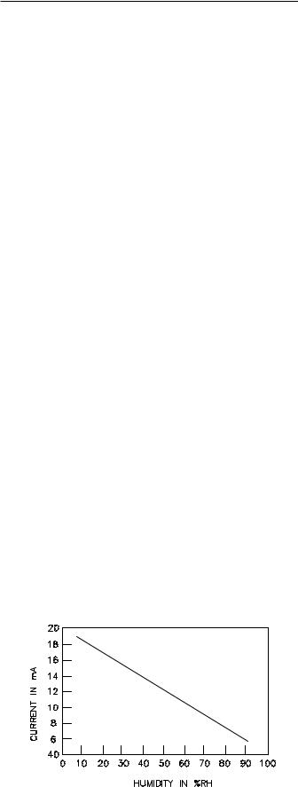
Exhaust/Comparative Enthalpy Module (ECEM - Optional 1U52 used on units with Statitrac and/or comparative enthalpy options)
The Exhaust/Comparative Enthalpy module receives information from the return air humidity sensor, the outside air humidity sensor, and the return air temperature sensor to utilize the lowest possible humidity level when considering economizer operation. In addition, it receives space pressure information which is used to maintain the space pressure to within the setpoint controlband. Refer to the table below for the Humidity vs Voltage input values.
7
Ventilation Control Module (VCM - Design special option only)
The Ventilation Control Module (VCM) is located in the filter section of the unit and is linked to the unit's UCM network. Using a "velocity pressure" sensing ring located in the fresh air section, allows the VCM to monitor and control the quantity of fresh air entering the unit to a minimum airflow setpoint.
An optional temperature sensor can be connected to the VCM which enables it to control a field installed fresh air preheater.
An optional CO2 sensor can be connected to the VCM to control CO2 reset. The reset function adjust the minimum CFM upward as the CO2 concentrations increase. The maximum effective (reset) setpoint value for fresh air entering the unit is limited to the systems operating CFM. The following table lists the Minimum Outside Air CFM vs Input Voltage.
Minimum Outside Air Setpoint w/VCM Module & TraqTM Sensing
Unit |
Input Volts |
CFM |
20 & 25 Ton |
0.5 - 4.5 vdc |
0 - 14000 |
30 Ton |
0.5 - 4.5 vdc |
0 - 17000 |
40 Ton |
0.5 - 4.5 vdc |
0 - 22000 |
50 & 55 Ton |
0.5 - 4.5 vdc |
0 - 28000 |
60 thru 75 Ton |
0.5 - 4.5 vdc |
0 - 33000 |
90 thru 130 Ton |
0.5 - 4.5 vdc |
0 - 46000 |
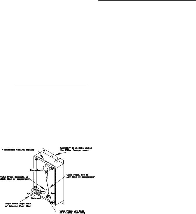
The velocity pressure transducer/solenoid assembly is illustrated below. Refer to the "TraqTM Sensor Sequence of Operation" section for VCM operation.
Velocity Pressure Transducer/Solenoid Assembly
Generic Building Automation System Module (GBAS - Optional 1U51 used with non-Trane building control systems)
The Generic Building Automation System (GBAS) module allows a non-Trane building control system to communicate with the rooftop unit and accepts external setpoints in form of analog inputs for cooling, heating, supply air pressure, and a binary Input for demand limit. Refer to the "Field Installed Control Wiring" section for the input wiring to the GBAS module and the various desired setpoints with the corresponding DC voltage inputs for both VAV and CV applications.
General Information (Continued)
For complete application details of the module, refer to Engineering Bulletin RT-EB-109.
Input Devices & System Functions
The descriptions of the following basic Input Devices used within the UCM network are to acquaint the operator with their function as they interface with the various modules. Refer to the unit's electrical schematic for the specific module connections.
Constant Volume & Variable Air Volume Units
Supply Air Temperature Sensor (3RT9)
Is an analog input device used with CV & VAV applications. It monitors the supply air temperature for; supply air temperature control (VAV), supply air temperature reset (VAV), supply air temperature low limiting (CV), supply air tempering (CV/VAV). It is mounted in the supply air discharge section of the unit and is connected to the RTM (1U48).
Return Air Temperature Sensor (3RT6)
Is an analog input device used with a return humidity sensor on CV & VAV applications when the comparative enthalpy option is ordered. It monitors the return air temperature and compares it to the outdoor temperature to establish which temperature is best suited to maintain the cooling requirements. It is mounted in the return air section and is connected to the ECEM (1U52).
Evaporator Temperature Sensor (3RT14 and 3RT15)
Is an analog input device used with CV & VAV applications. It monitors the refrigerant temperature inside the evaporator coil to prevent coil freezing. It is attached to the suction line near the evaporator coil and is connected to the SCM/MCM (1U49). It is factory set for 30 F and has an adjustable range of 25 F to 35 F. The compressors are staged "Off" as necessary to prevent icing. After the last compressor stage has been turned "Off", the compressors will be allowed to restart once the evaporator temperature rises 10 F above the "coil frost cutout temperature" and the minimum three minute "Off" time has elapsed.
Filter Switch (3S21)
Is a binary input device used on CV & VAV applications. It measures the pressure differential across the unit filters. It is mounted in the filter section and is connected to the RTM (1U48). A diagnostic SERVICE signal is sent to the remote panel if the pressure differential across the filters is at least 0.5" w.c.. The contacts will automatically open when the pressure differential across the filters decrease to 0.4" w.c.. The switch differential can be field adjusted between 0.17" w.c. to 5.0" w.c. ± 0.05" w.c..
Supply and Exhaust Airflow Proving Switches (3S68 and 3S69)
3S68 is a binary input device used on CV & VAV applications to signal the RTM when the supply fan is operating. It is located in the supply fan section of the unit and is connected to the RTM (1U48). During a request for fan operation, if the differential switch is detected to be open for 40 consecutive seconds; compressor operation is turned "Off", heat operation is turned "Off", the request for supply fan operation is turned "Off" and locked out, IGV's (if equipped) are "closed", exhaust dampers (if equipped) are "closed", economizer dampers (if equipped) are "closed", and a manual reset diagnostic is initiated.
8

General Information (Continued)
3S69 is a binary input device used on all rooftop units equipped with an exhaust fan. It is located in the exhaust fan section of the unit and is connected to the RTM (1U48). During a request for fan operation, if the differential switch is detected to be open for 40 consecutive seconds, the economizer is closed to the minimum position setpoint, the request for exhaust fan operation is turned "Off" and locked out, and a manual reset diagnostic is initiated. The fan failure lockout can be reset; at the Human Interface located in the unit's control panel, by Tracer, or by cycling the control power to the RTM (1S70 Off/On).
Lead-Lag
Is a selectable mode of operation on 40 thru 130 Ton units within the Human Interface. It alternates the starting between the first compressor of each refrigeration circuit. Only the compressor banks will switch, not the order of the compressors within a bank, providing the first compressor in each circuit had been activated during the same request for cooling.
Supply and Exhaust Fan Circuit Breakers (1CB1, 1CB2)
The supply fan and exhaust fan motors are protected by circuit breakers 1CB1 and 1CB2 respectively. They will trip and interrupt the power supply to the motors if the current
exceeds the breaker's "must trip" value. The rooftop module (RTM) will shut all system functions "Off" when an open fan proving switch is detected.
Low Pressure Control
Is accomplished using a binary input device on CV & VAV applications. LP cutouts are located on the suction lines near the scroll compressors.
The LPC contacts are designed to close when the suction pressure exceeds 22 ± 4 psig. If the LP control is open when a compressor is requested to start, none of the compressors on that circuit will be allowed to operate. They are locked out and a manual reset diagnostic is initiated.
The LP cutouts are designed to open if the suction pressure approaches 7 ± 4 psig. If the LP cutout opens after a compressor has started, all compressors operating on that circuit will be turned off immediately and will remain off for a minimum of three minutes.
If the LP cutout trips four consecutive times during the first three minutes of operation, the compressors on that circuit will be locked out and a manual reset diagnostic is initiated.
Saturated Condenser Temperature Sensors (2RT1 and 2RT2)
Are analog input devices used on CV & VAV applications mounted inside a temperature well located on a condenser tube bend. They monitor the saturated refrigerant temperature inside the condenser coil and are connected to the SCM/MCM (1U49). As the saturated refrigerant temperature varies due to operating conditions, the condenser fans are cycled "On" or "Off" as required to maintain acceptable operating pressures.
Head Pressure Control
is accomplished using two saturated refrigerant temperature sensors on CV & VAV applications. During a request for compressor operation, when the condensing temperature rises above the "lower limit" of the controlband, the Compressor Module (SCM/MCM) starts sequencing con-
denser fans "On". If the operating fans can not bring the condensing temperature to within the controlband, more fans are turned on. As the saturated condensing temperature approaches the lower limit of the controlband, fans are sequenced "Off". The minimum "On/Off" time for condenser fan staging is 5.2 seconds. If the system is operating at a given fan stage below 100% for 30 minutes and the saturated condensing temperature is above the "efficiency check point" setting, a fan stage will be added. If the saturated condensing temperature falls below the "efficiency check point" setting, the fan control will remain at the present operating stage. If a fan stage cycles four times within a 10 minute period, the control switches from controlling to the "lower limit" to a temperature equal to the "lower limit" minus the "temporary low limit suppression" setting. It will utilize this new "low limit" temperature for one hour to reduce condenser fan short cycling.
High Pressure Controls
High Pressure controls are located on the discharge lines near the scroll compressors. They are designed to open when the discharge pressure approaches 405 ± 7 psig. The controls reset automatically when the discharge pressure decreases to approximately 300 ± 20 psig. However, the compressors on that circuit are locked out and a manual reset diagnostic is initiated.
Outdoor Air Humidity Sensor (3U63)
Is an analog input device used on CV & VAV applications with 100% economizer. It monitors the outdoor humidity levels for economizer operation. It is mounted in the fresh air intake section and is connected to the RTM (1U48).
Return Air Humidity Sensor (3U64)
Is an analog input device used on CV & VAV applications with the comparative enthalpy option. It monitors the return air humidity level and compares it to the outdoor humidity level to establish which conditions are best suited to maintain the cooling requirements. It is mounted in the return air section and is connected to the ECEM (1U52).
Low Ambient Control
The low ambient modulating output on the compressor module is functional on all units with or without the low ambient option. When the compressor module has staged up to it's highest stage (stage 2 or 3 depending on unit size), the modulating output will be at 100% (10 VDC). When the control is at stage 1, the modulating output (0 to 10 VDC) will control the saturated condensing temperature to within the programmable "condensing temperature low ambient control point".
Status/Annunciator Output
Is an internal function within the RTM (1U48) module on CV
&VAV applications that provides;
a.diagnostic and mode status signals to the remote panel (LEDs) and to the Human Interface.
b.control of the binary Alarm output on the RTM.
c.control of the binary outputs on the GBAS module to inform the customer of the operational status and/or diagnostic conditions.
9
Low Ambient Compressor Lockout
Utilizes an analog input device for CV & VAV applications. When the system is configured for low ambient compressor lockout, the compressors are not allowed to operate if the temperature of the outside air falls below the lockout setpoint. When the temperature rises 5 F above the lockout setpoint, the compressors are allowed to operate. The setpoint for units without the low ambient option is 50 F. For units with the low ambient option, the setpoint is 0 F. The setpoints are adjustable at the Human Interface inside the unit control panel.
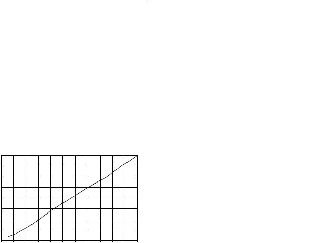
Space Pressure Transducer (3U62)
Is an analog input device used on CV & VAV applications with the Statitrac option. It modulates the exhaust dampers to keep the space pressure within the building to a customer designated controlband. It is mounted in the filter section just above the exhaust damper actuator and is connected to the ECEM (1U52). Field supplied pneumatic tubing must be connected between the space being controlled and the transducer assembly.
Transducer Voltage Output vs Pressure Input
|
4.0 |
|
|
|
|
|
|
|
|
|
|
|
|
3.5 |
|
|
|
|
|
|
|
|
|
|
|
|
3.0 |
|
|
|
|
|
|
|
|
|
|
|
Volts |
2.5 |
|
|
|
|
|
|
|
|
|
|
|
2.0 |
|
|
|
|
|
|
|
|
|
|
|
|
|
|
|
|
|
|
|
|
|
|
|
|
|
|
1.5 |
|
|
|
|
|
|
|
|
|
|
|
|
1.0 |
|
|
|
|
|
|
|
|
|
|
|
|
0.5 |
|
|
|
|
|
|
|
|
|
|
|
|
0.0 |
|
|
|
|
|
|
|
|
|
|
|
|
-0.5 |
0.0 |
0.5 |
1.0 |
1.5 |
2.0 |
2.5 |
3.0 |
3.5 |
4.0 |
4.5 |
5.0 |
|
|
|
|
|
Pressure (inches w.c.) |
|
|
|
||||
Morning Warm-Up - Zone Heat
When a system changes from an unoccupied to an occupied mode, or switches from STOPPED to AUTO, or power is applied to a unit with the MWU option, the heater in the unit or external heat will be brought on if the space temperature is below the MWU setpoint. The heat will remain on until the temperature reaches the MWU setpoint. If the unit is VAV, then the VAV box/unocc relay will continue to stay in the unoccupied position and the VFD/IGV output will stay at 100% during the MWU mode. When the MWU setpoint is reached and the heat mode is terminated, then the VAV box/unocc relay will switch to the occupied mode and the VFD/IGV output will be controlled by the duct static pressure. During Full Capacity MWU the economizer damper is held closed for as long as it takes to reach setpoint. During Cycling Capacity MWU the economizer damper is allowed to go to minimum position after one hour of operation if setpoint has not been reached.
Compressor Motor Winding Thermostats (2B7S1, 2B17S2, 2B27S5, 2B8S3, 2B18S4 & 2B28S6)
A thermostat is embedded in the motor windings of each Scroll compressor. Each thermostat is designed to open if the motor windings exceeds approximately 221 F. The thermostat will reset automatically when the winding temperature decreases to approximately 181 F. Rapid cycling, loss of charge, abnormally high suction temperatures, or the compressor running backwards could cause the thermostat to open. During a request for compressor operation, if the Compressor Module (SCM) detects a problem outside of it's normal parameters, it turns any operating
General Information (Continued)
compressor(s) on that circuit "Off", locks out all compressor operation for that circuit, and initiates a manual reset diagnostic.
Supply Air Temperature Low Limit
Uses the supply air temperature sensor input to modulate the economizer damper to minimum position in the event the supply air temperature falls below the occupied heating setpoint temperature.
Freezestat (4S12)
Is a binary input device used on CV & VAV units with Hydronic Heat. It is mounted in the heat section and connected to the Heat Module (1U50). If the temperature of the air entering the heating coil falls to 40 F, the normally open contacts on the freezestat closes signalling the Heat Module (1U50) and the Rooftop Module (RTM) to:
a.drive the Hydronic Heat Actuator (4U15) to the full open position.
b.turn the supply fan "Off".
c.closes the outside air damper;
d.turns "On" the SERVICE light at the Remote Panel.
e.initiates a "Freezestat" diagnostic to the Human
Interface.
High Duct Temp Thermostats (Optional 3S16, 3S17)
Are binary input devices used on CV & VAV applications with a Trane Communication Interface Module (TCI). They provide "high limit" shutdown of the unit and requires a manual reset. They are factory set to open if the supply air temperature reaches 240 F, or the return air temperature reaches 135 F. Once tripped, the thermostat can be reset by pressing the button located on the sensor once the air temperature has decreased approximately 25 F below the cutout point.
Compressor Circuit Breakers (1CB8, 1CB9, 1CB10, 1CB11 & 1CB14, 1CB15, 1CB16, 1CB17)
The Scroll Compressors are protected by circuit breakers which interrupt the power supply to the compressors if the current exceeds the breakers “must trip” value. During a request for compressor operation, if the Compressor Module (SCM) detects a problem outside of it's normal parameters, it turns any operating compressor(s) on that circuit "Off", locks out all compressor operation for that circuit, and initiates a manual reset diagnostic.
Constant Volume (CV) Units
Zone Temperature - Cooling
Relies on input from a sensor located directly in the space, while a system is in the occupied "Cooling" mode. It modulates the economizer (if equipped) and/or stages the mechanical cooling "On and Off" as required to maintain the zone temperature to within the cooling setpoint deadband.
Zone Temperature - Heating
Relies on input from a sensor located directly in the space, while a system is in the occupied "Heating" mode or an unoccupied period, to stage the heat "on and off" or to modulate the heating valve (hydronic heat only) as required to maintain the zone temperature to within the heating setpoint deadband. The supply fan will be requested to operate any time there is a requested for heat. On gas heat units, the fan will continue to run for 60 seconds after the furnace is turned off.
Supply Air Tempering
On CV units equipped with staged heat, if the supply air temperature falls 10 F below the occupied heating setpoint temperature while the heater is "Off", the first stage of heat will be turned "On". The heater is turned "Off" when the supply air temperature reaches 10 F above the occupied heating setpoint temperature.
10
Variable Air Volume (VAV) Units
Occupied Heating - Supply Air Temperature
When a VAV units is equipped with "Modulating Heat", and the system is in an occupied mode, and the field supplied changeover relay contacts (5K87) have closed, the supply air temperature will be controlled to the customer specified supply air heating setpoint. It will remain in the heating status until the changeover relay contacts are opened.
Occupied Cooling - Supply Air Temperature
When a VAV unit is in the occupied mode, the supply air temperature will be controlled to the customers specified supply air cooling setpoint by modulating the economizer and/or staging the mechanical cooling "On and Off" as required. The changeover relay contacts must be open on units with "Modulating Heat" for the cooling to operate.
Daytime Warm-up
On VAV units equipped with heat, if the zone temperature falls below the daytime warm-up initiate temperature during the occupied mode, the system will switch to full airflow. During this mode, the VAV box/unocc relay, RTM K3, will be energized (this is to signal the VAV boxes to go to 100%). After the VAV box max stroke time has elapsed (factory set at 6 minutes), the VFD/IGV output will be set to 100%. The airflow will be at 100% and the heat will be turned on to control to the occupied heating setpoint. When the zone temperature reaches the daytime warm-up termination setpoint, the heat will be turned off, the K3 relay will be de-energized, releasing the VAV boxes, the VFD/IGV output will go back to duct static pressure control
General Information (Continued)
and the unit will return to discharge air control. If the occ zone heating setpoint is less than the DWU terminate setpoint, the heat will turn off when the occ zone heat setpoint is reached, but it will stay in DWU mode and cycle the heat to maintain setpoint.
Unoccupied Heating - Zone Temperature
When a VAV unit is equipped with gas, electric, or hydronic heat and is in the unoccupied mode, the zone temperature will be controlled to within the customers specified setpoint deadband. During an unoccupied mode for a VAV unit, the VAV box/unocc relay will be in the unoccupied position and the VFD/IGV output will be at 100%. This means that if there is a call for heat (or cool) and the supply fan comes on, it will be at full airflow and the VAV boxes in the space will need to be 100% open as signaled by the VAV box/ unocc relay.
Supply Air Tempering
On VAV units equipped with "Modulating Heat", if the supply air temperature falls 10 F below the supply air temperature setpoint, the hydronic heat valve will modulate to maintain the supply air temperature to within the low end of the setpoint deadband.
Supply Duct Static Pressure Control (Occupied)
The RTM relies on input from the duct pressure transducer when a unit is equipped with Inlet Guide Vanes or a Variable Frequency Drive to position the Inlet Guide Vanes or set the supply fan speed to maintain the supply duct static pressure to within the static pressure setpoint deadband. Refer to the Transducer Voltage Output vs Pressure Input values listed in the Space Pressure Transducer (3U62) section.
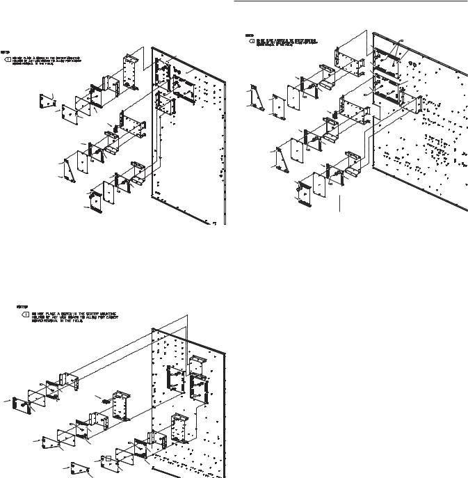
Unit Component Layout and "Shipwith" Locations
11 |
General Information (Continued)
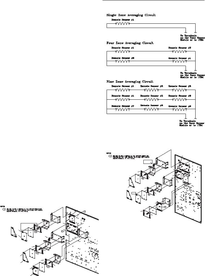
Space Temperature Averaging
Space Temperature Averaging with Multiple Sensors
Space temperature averaging for Constant Volume applications is accomplished by wiring a number of remote sensors in a series/parallel circuit.
The fewest number of sensors required to accomplish space temperature averaging is four. Figure 8 illustrates a single sensor circuit (Single Zone), four sensors wired in a series/parallel circuit (Four Zone), nine sensors wired in a series/parallel circuit (Nine Zone). Any number squared, is the number of remote sensors required.
Wiring termination will depend on the type of remote panel or control configuration for the system. Refer to the wiring diagrams that shipped with the unit.
Unit Control Modules (UCM)
Unit control modules are microelectronic circuit boards designed to perform specific unit functions. These modules through Proportional/Integral control algorithms provide the best possible comfort level for the customer. They are mounted in the control panel and are factory wired to their respective internal components. They receive and interpret information from other unit modules, sensors, remote panels, and customer binary contacts to satisfy the applicable request for economizing, mechanical cooling, heating, and ventilation. Figure 9 below illustrates the typical location of each "1U" designated module.
Control Module Locations for S_HF 30 Ton Units
|
|
J2-1 |
|
|
RTM |
|
|
1U48 |
|
1TB9 |
|
|
|
J1-1 |
ECEM |
|
|
1U52 |
|
J2-1 |
J1-1 |
|
Bracket |
|
|
|
1PCB MOD |
Bracket |
SCM |
1U55 |
1U49 |
|
|
|
|
|
|
J2-1 |
Bracket |
J2-1 |
|
|
|
|
|
|
|
|
|
|
|
|
Heat MOD |
J1-1 |
|
|
|
|
|
J1-1 |
|
|
1U50 |
|
|
|
|
|
|
|
|
J1-1 |
|
Bracket |
|
Mounting |
|
|
|
|
|
|
|
|
|
Plate |
|
|
Bracket |
|
|
|
|
|
|
|
|
|
J2-1 |
Control Module Locations for S_HF 20 & 25 Ton Units
|
GBAS MOD |
TCI MOD |
1U51 |
|
|
1U54 |
OR |
|
Mounting J2-1 |
|
|
|
LCI MOD |
||||
|
SCM |
|
Plate |
J1-1 |
||
|
|
|
1U54 |
|
|
|
Bracket |
1U49 |
|
VOM |
|
|
|
|
|
1U53 |
|
Bracket |
||
|
|
|
|
|||
|
J2-1 |
|
|
J1-1 |
|
|
Bracket
J2-1
Heat MOD
1U50
Mounting
Plate
 J2-1
J2-1
Bracket
|
J1-1 |
|
RTM |
J2-1 |
1U48 |
J1-1 |
|
J1-1
1TB9
TCI MOD |
|
|
Bracket |
Bracket |
1U54 |
|
|
||
|
|
|
|
|
OR |
|
ECEM |
|
|
LCI MOD |
|
|
||
1U52 |
|
|
||
1U54 |
|
|
|
|
|
J1-1 |
|
|
|
|
|
|
|
|
1PCB MOD |
|
|
|
|
1U55 |
|
|
J2-1 |
|
J2-1 |
|
|
GBAS MOD |
|
|
|
|
1U51 |
|
|
|
Mounting J1-1 |
|
|
J1-1 |
|
Plate |
|
Bracket |
|
|
|
|
|
|
|
VOM |
|
|
|
|
1U53 |
|
J2-1 |
|
J2-1 |
|
|
|
J1-1 |
Mounting |
|
Plate |
||
|
12
General Information (Continued)
Control Module Locations for S_HF 40, 60, 70 & 75 Ton Units
|
MCM |
Bracket |
1U49 |
|
|
RTM |
|
Bracket |
1U48 |
|
|
|
|
Heat MOD |
|
|
1U50 |
|
J2-1 |
Mounting J2-1 |
|
|
Plate |
|
J1-1 
TCI MOD J1-1 |
|
J1-1 |
Bracket |
|
1U54 |
OR |
J2-1 |
1TB9 |
|
|
|
|||
|
LCI MOD |
|
|
|
|
1U54 |
|
|
|
|
|
J1-1 |
|
Bracket |
|
|
|
|
|
|
|
|
|
Bracket |
|
|
|
J2-1 |
|
|
J2-1 |
|
|
|
|
|
|
ECEM |
|
|
|
|
1U52 |
|
|
J1-1 |
|
J1-1 |
|
|
|
Mounting |
|
|
|
|
Plate |
|
Bracket |
|
|
1PCB MOD |
|
|
|
|
1U55 |
|
J2-1 |
|
|
J2-1 |
|
|
GBAS MOD 1U51
J1-1
Mounting
Plate
VOM
1U53
Control Module Locations for S_HF 50 & 55 Ton Units
|
|
|
|
J2-1 |
MCM |
|
|
|
|
|
1U49 |
|
|
|
|
J1-1 |
|
|
|
|
Heat MOD |
J2-1 |
|
|
|
|
1U50 |
|
|
TCI MOD |
|
|
|
RTM |
|
1U54 |
|
|
J1-1 |
|
|
|
|
|
1U48 |
||
|
OR |
Mounting |
|
Bracket |
|
|
Plate |
|
|
|
|
J2-1 |
LCI MOD |
|
J1-1 |
|
|
1U54 |
|
|
Bracket |
|
|
|
|
|
|
||
|
J2-1 |
|
|
J2-1 |
|
|
|
|
|
|
|
J1-1 |
|
|
|
|
|
|
|
|
|
1TB9 |
|
|
J1-1 |
|
|
|
|
|
|
|
ECEM |
|
|
|
|
|
1U52 |
|
|
|
|
|
J1-1 |
Bracket |
|
|
1PCB MOD |
|
|
|
|
|
1U55 |
|
|
Bracket |
|
|
|
|
|
|
|
|
J2-1 |
|
|
J2-1 |
|
|
|
|
|
|
|
|
J1-1 |
|
|
J1-1 |
|
|
|
Mounting |
|
|
|
|
|
|
|
|
|
|
|
|
Plate |
|
|
|
|
|
J2-1 |
Bracket |
|
|
|
|
|
|
|
|
|
|
|
J2-1 |
|
|
|
|
|
GBAS MOD |
|
|
|
|
J1-1 |
1U51 |
|
|
|
|
|
|
|
|
|
|
|
Mounting |
|
|
|
|
|
Plate |
|
|
|
|
VOM |
|
|
|
|
|
1U53 |
|
|
Control Module Locations for S_HG 90 - 130 Ton Units
Bracket
|
|
RTM |
|
Bracket |
1U48 |
|
|
|
|
GBAS MOD |
|
|
Mounting 1U51 |
|
|
Plate |
|
VOM |
|
Bracket |
1U53 |
|
|
|
|
|
|
J1-1 |
1TB9 |
|
|
J1-1
 J2-1 Bracket
J2-1 |
ECEM |
|
Bracket |
MCM |
|
|
1U49 |
||
|
1U52 |
|
|
|
|
Mounting |
|
|
|
|
Plate |
|
Bracket |
|
1PCB MOD |
J1-1 |
Heat MOD |
|
|
1U55 |
|
|
1U50 |
|
J1-1 |
|
|
|
|
|
|
Mounting |
|
|
|
|
J2-1 |
|
|
|
|
Plate |
|
|
|
|
|
|
|
|
J2-1 |
LCI MOD |
J1-1 |
|
|
|
1U54 |
|
|
|
TCI MOD |
OR J1-1 |
|
|
|
1U54 |
|
|
|
|
J1-1 |
|
J2-1 |
|
|
|
|
|
|
|
|
|
J2-1 |
|
|
|
J2-1 |
|
|
13

Section One |
|
About The Manual ............................................................... |
2 |
Literature Change History ................................................ |
2 |
Overview of Manual ......................................................... |
2 |
Section Two |
|
General Information ............................................................. |
4 |
Model Number Description .............................................. |
4 |
Hazard Identification ........................................................ |
6 |
Commonly Used Acronyms ............................................. |
6 |
Unit Description ................................................................ |
6 |
Input Devices & System Functions .................................. |
8 |
Constant Volume & Variable Air Volume Units ................ |
8 |
Constant Volume (CV) Units .......................................... |
10 |
Variable Air Volume (VAV) Units .................................... |
11 |
Space Temperature Averaging ....................................... |
12 |
Unit Control Modules (UCM) .......................................... |
12 |
Section Three |
|
Installation .......................................................................... |
14 |
Unit Inspection ............................................................... |
14 |
Storage ........................................................................... |
14 |
Unit Clearances ............................................................. |
14 |
Unit Dimensions & Weight Information .......................... |
14 |
Roof Curb and Ductwork ............................................... |
22 |
Pitch Pocket Location .................................................... |
23 |
Unit Rigging & Placement .............................................. |
23 |
General Unit Requirements ........................................... |
25 |
Main Electrical Power Requirements ............................. |
25 |
Field Installed Control Wiring ......................................... |
25 |
Requirements for Electric Heat Units ............................ |
25 |
Requirements for Gas Heat ........................................... |
25 |
Requirements for Hot Water Heat (SLH_) ..................... |
25 |
Requirements for Steam Heat (SSH_) .......................... |
26 |
O/A Pressure Sensor and Tubing Installation ............... |
26 |
Condensate Drain Connection ....................................... |
27 |
Shipping Fasteners ........................................................ |
27 |
O/A Sensor & Tubing Installation ................................... |
31 |
Units with Statitrac™; .................................................... |
31 |
Gas Heat Units (SFH_) .................................................. |
32 |
Connecting the Gas Supply Line to the Furnace |
|
Gas Train ........................................................................ |
32 |
Flue Assembly Installation ............................................. |
34 |
Hot Water Heat Units (SLH_) ........................................ |
34 |
Steam Heat Units (SSH_) .............................................. |
35 |
Disconnect Switch External Handle ............................... |
38 |
Electric Heat Units (SEH_) ............................................ |
38 |
Main Unit Power Wiring ................................................. |
38 |
Disconnect Switch Sizing (DSS) .................................... |
44 |
Field Installed Control Wiring ......................................... |
45 |
Controls using 24 VAC ................................................... |
45 |
Controls using DC Analog Input/Outputs ....................... |
45 |
Constant Volume System Controls ................................ |
45 |
Variable Air Volume System Controls ............................ |
46 |
Constant Volume or Variable Air Volume System |
|
Controls .......................................................................... |
46 |
Table of Contents |
|
Section Four |
|
Unit Start-Up ...................................................................... |
55 |
Cooling Sequence of Operation .................................... |
55 |
Gas Heating Sequence of Operation ............................. |
56 |
Fenwal Ignition System .................................................. |
56 |
Honeywell Ignition System ............................................. |
56 |
Modulating Gas Sequence of Operation ....................... |
57 |
Flame Failure ................................................................. |
57 |
Electric Heat Sequence of Operation ............................ |
58 |
Wet Heat Sequence of Operation .................................. |
58 |
Electrical Phasing .......................................................... |
59 |
Voltage Supply and Voltage Imbalance ......................... |
60 |
Service Test Guide for Component Operation ............... |
61 |
Verifying Proper Fan Rotation ....................................... |
63 |
If all of the fans are rotating backwards;........................ |
63 |
System Airflow Measurements ...................................... |
63 |
Constant Volume Systems ............................................. |
63 |
Variable Air Volume Systems ......................................... |
65 |
Exhaust Airflow Measurement ....................................... |
66 |
TraqTM Sensor Airflow Measurement ........................... |
66 |
Economizer Damper Adjustment ................................... |
80 |
Compressor Start-Up ..................................................... |
82 |
Compressor Operational Sounds .................................. |
83 |
Thermostatic Expansion Valves ..................................... |
93 |
Charging by Subcooling ................................................. |
93 |
Low Ambient Dampers ................................................... |
93 |
Electric, Steam and Hot Water Start-Up ........................ |
94 |
Gas Furnace Start-Up .................................................... |
94 |
Two Stage Gas Furnace ................................................ |
95 |
Full Modulating Gas Furnace ......................................... |
97 |
Limited Modulating Gas Furnace ................................... |
98 |
Final Unit Checkout ........................................................ |
99 |
Section Five |
|
Service & Maintenance.................................................... |
100 |
Fan Belt Adjustment ..................................................... |
104 |
Scroll Compressor Replacement ................................. |
105 |
VFD Programming Parameters ................................... |
106 |
Monthly Maintenance ................................................... |
107 |
Filters............................................................................ |
107 |
Cooling Season ............................................................ |
107 |
Heating Season ............................................................ |
108 |
Coil Cleaning ................................................................ |
108 |
Final Process ............................................................... |
109 |
Index ............................................................................... |
111 |
UV ................................................................................... |
114 |
Warranty ......................................................................... |
114 |
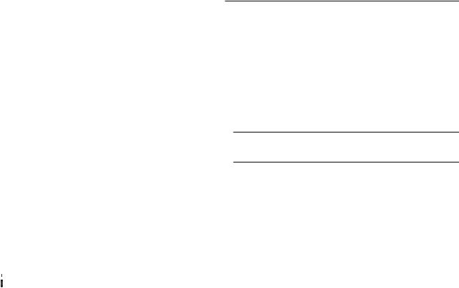
Unit Inspection
As soon as the unit arrives at the job site
[ ] Verify that the nameplate data matches the data on the sales order and bill of lading (including electrical data).
[ ] Verify that the power supply complies with the unit nameplate specifications.
[ ] Verify that the power supply complies with the electric heater specifications on the uit nameplate.
[ ] Visually inspect the exterior of the unit, including the roof, for signs of shipping damage.
[ ] Check for material shortages. Refer to the Component Layout and Shipwith Location illustration.
If the job site inspection of the unit reveals damage or material shortages, file a claim with the carrier immediately. Specify the type and extent of the damage on the "bill of lading" before signing.
[ ] Visually inspect the internal components for shipping damage as soon as possible after delivery and before it is stored. Do not walk on the sheet metal base pans.


 WARNING
No Step Surface!
FOR ACCESS TO COMPONENTS, THE BASE SHEET METAL SURFACE MUST BE REINFORCED.
Bridging between the unit's main supports may consist of multiple 2 by 12 boards or sheet metal grating.
Failure to comply could result in death or severe personal injury from falling.
[ ] If concealed damage is discovered, notify the carrier's terminal of damage immediately by phone and by mail. Concealed damage must be reported within 15 days.
Request an immediate joint inspection of the damage by the carrier and the consignee. Do not remove damaged material from the receiving location. Take photos of the damage, if possible. The owner must provide reasonable evidence that the damage did not occur after delivery.
[ ] Remove the protective plastic coverings that shipped over the compressors.
Installation
Storage
Take precautions to prevent condensate from forming inside the unit’s electrical compartments and motors if:
a.the unit is stored before it is installed; or,
b.the unit is set on the roof curb, and temporary heat is provided in the building. Isolate all side panel service entrances and base pan openings (e.g., conduit holes, S/A and R/A openings, and flue openings) from the ambient air until the unit is ready for startup.
Note: Do not use the unit's heater for temporary heat without first completing the startup procedure detailed under "Starting the Unit".
Trane will not assume any responsibility for
equipment damage resulting from condensate accumulation on the unit's electrical and/or mechanical components.
Unit Clearances
Figure 3-1 illustrates the minimum operating and service clearances for either a single or multiple unit installation. These clearances are the minimum distances necessary to assure adequate serviceability, cataloged unit capacity, and peak operating efficiency.
Providing less than the recommended clearances may result in condenser coil starvation, "short-circuiting" of exhaust and economizer airflows, or recirculation of hot condenser air.
Unit Dimensions & Weight Information
Overall unit dimensional data for a SAHF (20 thru 75 Ton) cooling only unit is illustrated in Figure 3-2A. Tables 3-1A, 3-1B, and 3-1C list the dimensions. Dimensional data for SEH_, SFH_, SLH_, SSH_, and SXH_ (20 thru 130 Ton) units are illustrated in Figure 3-2B. Tables 3-2A, 3-2B, and 3-2C list the dimensions for the 20 thru 75 Ton units. Dimensions for 90 through 130 Ton units are listed on the illustration in Figure 3-2C.
A Center-of-Gravity illustration and the dimensional data is shown in Figure 3-3.
Table 3-3 list the typical unit and curb operating weights. Weights shown represent approximate operating weights. Actual weights are stamped on the unit nameplate.
14
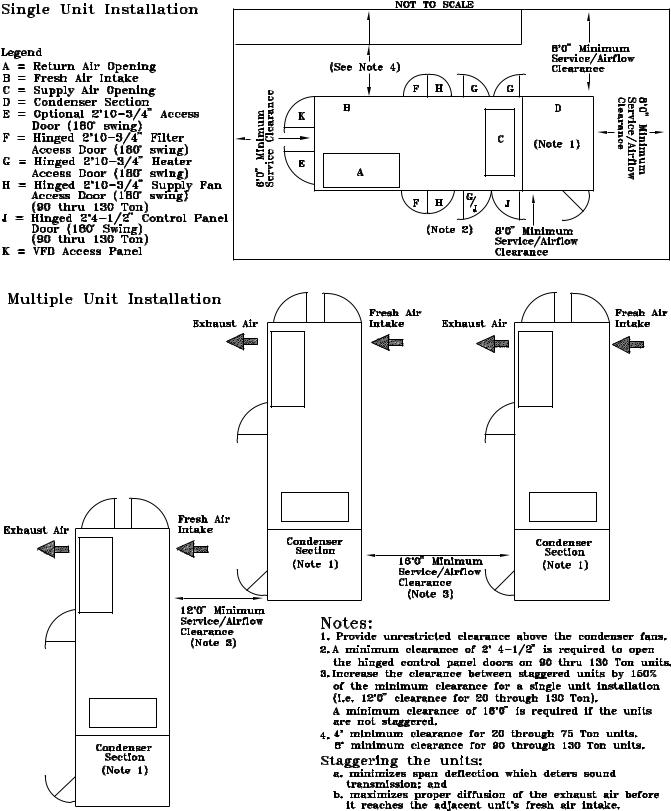
Figure 3-1
Minimum Operation and Service Clearances for Single & Multiple Unit Installation
15
Figure 3-2A
SAHF Cooling-Only Units (20 thru 75 Ton)
16
Table 3-1A |
|
|
|
|
|
|
|
|
|
|
|
|
|
|
|
Installation (Continued) |
|
|
|
|
|
|
|
||||||||||
|
|
|
|
|
|
|
|
|
|
|
|
|
|
|
|
|
|
|
|
|
|
|
|
|
|
|
|
|
|
|
|
|
|
Unit Dimensional Data |
|
|
|
|
|
|
|
|
|
|
|
|
|
|
|
|
|
|
|
|
|
|
|
|
|
|
|
||||||
Unit |
|
|
|
|
|
|
|
|
|
|
|
Dimensions |
|
|
|
|
|
|
|
|
|
|
|
|
|
|
|
|
|||||
Size |
|
|
|
A |
|
B |
|
|
C |
|
|
|
D |
|
|
E |
|
|
|
F |
|
|
G |
|
H |
J |
|
|
|
||||
20 & 25 Ton |
21'-9 3/4" |
|
5'-3 1/8" |
|
7'-6 1/2" 5'-8 15/16" |
3'-9 |
5/16" |
|
12'-6" |
|
1" |
|
7' |
|
1'-3 1/2" |
||||||||||||||||||
30 Ton |
|
21'-9 3/4" |
|
5'-8 5/8" |
|
7'-6 1/2" |
6'-2 7/16" |
|
4'-9 |
5/16" |
|
12'-6" |
|
1" |
|
7' |
1'-3 1/2" |
||||||||||||||||
40 Ton |
|
|
27'-0" |
|
|
6'-1 5/8" |
|
7'-6 1/2" |
6'-7 3/8" |
|
5'-9 |
5/16" |
|
15'-11 1/8" |
|
1" |
|
8' |
|
2'-5" |
|||||||||||||
50 & 55 Ton |
|
29'-8" |
|
|
5'-3 1/8" |
|
7'-6 1/2" |
5'-8 7/8" |
|
6'-9 |
5/16" |
|
15'-11 1/8" |
|
1" |
|
8' |
|
2'-5" |
||||||||||||||
60 Ton |
|
|
27'-0" |
|
|
6'-1 5/8" |
|
9'-8" |
|
|
6'-7 3/8" |
|
5'-9 |
5/16" |
|
15'-11 1/8" |
|
1" |
|
8' |
|
2'-5" |
|||||||||||
70 & 75 Ton |
|
27'-0" |
|
|
6'-1 5/8" |
|
9'-8" |
|
|
6'-7 3/8" |
|
5'-9 |
5/16" |
|
15'-11 1/8" |
|
1" |
|
8' |
1'-4" |
|||||||||||||
Table 3-1B |
|
|
|
|
|
|
|
|
|
|
|
|
|
|
|
|
|
|
|
|
|
|
|
|
|
|
|
|
|
|
|
|
|
Unit Base Dimensional Data |
|
|
|
|
|
|
|
|
|
|
|
|
|
|
|
|
|
|
|
|
|
|
|
|
|
|
|
||||||
Unit |
|
|
|
|
|
|
|
|
|
|
|
|
Dimensions |
|
|
|
|
|
|
|
|
|
|
|
|
|
|
|
|
||||
Size |
|
|
|
A |
B |
|
|
C |
|
|
|
|
D |
|
|
E |
|
|
F |
|
G |
|
|
|
|
|
|||||||
20 - 30 Ton |
|
14'-0 1/4" |
2'-2 1/2" |
11 3/4" |
|
5'-7" |
|
|
3'-4 |
3/8" |
|
5 13/16" |
6'-6 15/16" |
|
|
|
|||||||||||||||||
|
|
|
|
|
|
|
|
|
|
|
|
|
|
|
|
|
|
|
|
|
|
|
|
|
|
||||||||
40 - 55 Ton |
16'-7 13/16" |
2'-5" |
|
11 3/4" |
|
5'-7" |
|
|
3'-4 |
3/8" |
|
5 13/16" |
7'-8 3/16" |
|
|
|
|||||||||||||||||
|
|
|
|
|
|
|
|
|
|
|
|
|
|
|
|
|
|
|
|
|
|
|
|
|
|
||||||||
60 Ton |
|
16'-7 13/16" |
2'-5" |
|
1'-4 9/16" |
6'-10 |
7/8" |
4'-5 |
3/8" |
|
5 13/16" |
7'-8 3/16" |
|
|
|
||||||||||||||||||
|
|
|
|
|
|
|
|
|
|
|
|
|
|
|
|
|
|
|
|
|
|
|
|
|
|||||||||
70 - 75 Ton |
16'-7 13/16" |
2'-5" |
|
1'-4 9/16" |
6'-10 |
7/8" |
4'-5 |
3/8" |
|
5 13/16" |
7'-8 3/16" |
|
|
|
|||||||||||||||||||
Table 3-1C |
|
|
|
|
|
|
|
|
|
|
|
|
|
|
|
|
|
|
|
|
|
|
|
|
|
|
|
|
|
|
|
|
|
Electrical Entrance Data |
|
|
|
|
|
|
|
|
|
|
|
|
|
|
|
|
|
|
|
|
|
|
|
|
|
|
|
||||||
Unit |
|
|
|
|
|
|
|
Dimensions |
|
|
|
|
|
|
|
|
|
|
|
|
|
|
|
|
|
|
|
|
|||||
Size |
F |
|
|
G |
|
|
H |
|
|
J |
|
K |
|
|
L |
|
M |
|
N |
|
|
|
|
|
|
|
|||||||
20, 25, & 30 |
8 7/32" |
|
6 31/32" |
15 21/32" |
13 21/32" |
9 17/32" |
|
8 1/2" |
|
18 1/16" |
|
19 9/16" |
|
|
|
|
|
|
|
|
|
||||||||||||
50 & 55 Ton |
|
|
|
|
|
|
|
|
|
|
|
|
|
|
|
|
|
|
|
|
|
|
|
|
|
|
|
|
|
|
|
|
|
40, 60, 70 |
8 3/4" |
|
7 3/4" |
|
|
17 7/8" |
15 7/8" |
9 29/32" |
|
10 1/16" |
20 13/32" |
22 5/32" |
|
|
|
|
|
|
|
|
|
||||||||||||
& 75 Ton |
|
|
|
|
|
|
|
|
|
|
|
|
|
|
|
|
|
|
|
|
|
|
|
|
|
|
|
|
|
|
|
|
|
17
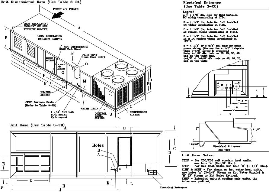
Figure 3-2B
SEHF, SFHF, SLHF, SSHF, SXHF Units (20 thru 75 Ton)
18
Installation (Continued)
Table 3-2A
Unit Dimensional Data
Unit |
|
|
|
Dimensions |
|
|
|
|
|
|
|
||
Size |
A |
B |
C |
|
D |
|
E |
F |
G |
H |
J |
|
|
20 & 25 Ton |
24'-1 3/8" |
5'-3 1/8" |
7'-6 1/2" |
5'-8 15/16" |
3'-9 |
5/16" |
13'-3" |
1" |
7' |
1'-3 1/2" |
|||
|
|
|
|
|
|
|
|
|
|
|
|
|
|
30 Ton |
24'-1 3/8" |
5'-8 5/8" |
7'-6 1/2" |
6'-2 |
3/8" |
4'-9 |
5/16" |
13'-3" |
1" |
7' |
1'-3 1/2" |
||
40 Ton |
30'-2 1/2" |
6'-1 5/8" |
7'-6 1/2" |
6'-7 |
3/8" |
5'-9 |
5/16" |
15'-11 1/8" |
1" |
8' |
|
2'-5" |
|
50 & 55 Ton |
32'-10 1/2" |
5'-3 1/8" |
7'-6 1/2" |
5'-8 7/8" |
6'-9 |
5/16" |
15'-11 1/8" |
1" |
8' |
|
2'-5" |
||
60 Ton |
30'-2 1/2" |
6'-1 5/8" |
9'-8" |
6'-7 3/8" |
5'-9 |
5/16" |
15'-11 1/8" |
1" |
8' |
|
2'-5" |
||
70 & 75 Ton |
30'-2 1/2" |
6'-1 5/8" |
9'-8" |
6'-7 3/8" |
5'-9 |
5/16" |
15'-11 1/8" |
1" |
8' |
|
1'-4" |
||
Dimensions
K |
L |
M |
|
N |
O |
16'-7" |
16'-6" |
8 |
1/8" |
6 1/4" |
9" |
16'-7" |
16'-6" |
8 |
1/8" |
6 1/4" |
9" |
19'-7" |
See Note |
8 1/8" |
6 1/4" |
9" |
|
19'-7" |
See Note |
8 1/8" |
6 1/4" |
9" |
|
19'-7" |
See Note |
8 1/8" |
6 1/4" |
9" |
|
Note: 19'-6" for SFHF "Low Heat" units or 20'-3" for SFHF "High Heat" units.
Table 3-2B
Unit Base Dimensional Data
|
Unit |
|
|
|
|
Dimensions |
|
|
|
|
|
|
|
|||
|
Size |
A |
|
B |
C |
D |
|
E |
|
F |
|
G |
|
H |
|
|
20 |
- 30 Ton |
16'-3 3/16" |
2'-2 1/2" |
5 13/16" |
5'- |
7" |
3'-4 |
3/8" |
5 |
13/16" 6'-6 |
15/16" 15'-5 |
5/16" |
||||
40 |
- 55 Ton |
19'-10 |
5/16" |
2'-5" |
7 1/16" |
5'- |
7" |
3'-4 |
3/8" |
5 |
13/16" |
7'-8 |
3/16" |
18'-11 |
11/16" |
|
60 Ton |
19'-10 |
5/16" |
2'-5" |
6 1/16" |
Note |
1 |
4'-5 |
3/8" |
5 13/16" |
7'-8 |
3/16" |
18'-11 11/16" |
||||
|
|
|
|
|
|
|
|
|
|
|
|
|
|
|
||
70 |
- 75 Ton |
19'-10 |
5/16" |
2'-5" |
6 1/16" |
Note |
1 |
4'-5 |
3/8" |
5 13/16" |
7'-8 |
3/16" |
18'-11 11/16" |
|||
|
|
|
|
|
|
|
|
|
|
|
|
|
|
|
|
|
|
Unit |
Dimensions |
|
||
|
Size |
J |
K |
|
L |
20 |
- 30 Ton |
16'-9 3/4" |
8 13/16" |
|
9 1/16" |
40 |
- 55 Ton |
20'-1 3/4" |
8 3/16" |
|
9 1/16" |
60 Ton |
20'-1 3/4" |
8 3/16" |
|
9 1/16" |
|
70 |
- 75 Ton |
20'-1 3/4" |
8 3/16" |
|
9 1/16" |
Note:
1. 5'-5 15/16" for SEHF units or 7'-8 1/2" for SFHF, SLHF, SSHF, SXHF units.
Table 3-2C
Electrical Entrance Data
Unit |
|
|
|
Dimensions |
|
|
|
|
||
Size |
F |
G |
H |
J |
|
K |
|
L |
M |
N |
20, 25, & 30 |
8 7/32" |
6 31/32" |
15 21/32" |
13 21/32" |
9 |
17/32" |
8 |
1/2" |
18 1/16" |
19 9/16" |
50 & 55 Ton |
|
|
|
|
|
|
|
|
|
|
40, 60, 70 |
8 3/4" |
7 3/4" |
17 7/8" |
15 7/8" |
9 |
29/32" |
10 |
1/16" |
20 13/32" |
22 5/32" |
& 75 Ton |
|
|
|
|
|
|
|
|
|
|
Table 3-2D
CPVC Dimensional Data
Unit Size |
Furnace |
Dimensions (Note) |
|
|
Size/MBH |
Length |
Height |
20 & 25 Ton |
Low = 235 |
195-5/32" |
9-5/32" |
|
High = 500 |
195-5/32" |
9-5/32" |
30 Ton |
Low = 350 |
195-5/32" |
9-5/32" |
|
High = 500 |
195-5/32" |
9-5/32" |
40 Ton |
Low = 350 |
240-1/8" |
9-5/32" |
|
High = 850 |
231-1/8" |
9-5/32" |
Unit Size |
Furnace |
Dimensions (Note) |
|
|
Size/MBH |
Length |
Height |
50 - 75 Ton |
Low = 500 |
240-1/8" |
9-5/32" |
|
High = 850 |
231-1/8" |
9-5/32" |
90 -130 Ton |
1000 |
267-3/16" |
10-11/32" |
Note: The length dimension is from the exhaust end of the unit. The height dimension is from the bottom of the unit base rail.
19
Figure 3-2C
S_HG Cooling & Heating Units (90 through 130 Ton)
20
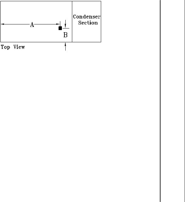
Figure 3-3
Center-of-Gravity Data (See Note 1)
|
|
Units with |
|
Units |
|
|
|
|
Units |
|
|
|
|
|
|
100% |
|
without |
|
with Supply & |
|||||||
|
|
Exhaust Fan |
Exhaust Fan |
Exhaust VFD |
|||||||||
Unit |
Unit |
Dim. Dim. |
Dim. Dim. |
Dim. Dim. |
|||||||||
Model |
Size |
A |
B |
|
A |
B |
|
|
A |
B |
|
|
|
SAHF |
C20 |
12' 6" |
3' 8" |
13' 5" |
3' |
10" 11' 10" |
3' 9" |
||||||
|
C25 |
12' 9" |
3' 8" |
13' 7" |
3' |
10" |
12' 0" |
|
3' 9" |
||||
|
C30 |
12' 5" |
3' 8" |
13' 3" |
3' |
10" |
11' 9" |
|
3' 9" |
||||
|
C40 |
15' 7" |
3' 10" |
16' 9" |
4' 0" |
14' 10" |
3' 11" |
||||||
|
C50 |
16' 7" |
3' 10" |
17' 9" |
4' 0" |
15' 8" |
|
3' 11" |
|||||
|
C55 |
16' 10" |
3' 10" |
18' 1" |
4' 0" |
16' 0" |
|
3' 11" |
|||||
|
C60 |
15' 7" |
4' 7" |
16' 11" 4' 10" 14' 10" |
4' 8" |
||||||||
|
C70 |
15' 10" |
4' 8" |
17' 1" |
4' 10" |
15' 2" |
|
4' 9" |
|||||
|
C75 |
15' 11" |
4' 8" |
17' 2" |
4' 10" |
15' 2" |
|
4' 9" |
|||||
SEHF |
C20 |
13' 8" |
3' 8" |
14' 7" |
3' 10" 12' 11" |
|
3' 9" |
||||||
SLHF |
C25 |
13' 10" |
3' 7" |
14' 9" |
3' 9" |
13' 1" |
|
3' 9" |
|||||
SSHF |
C30 |
13' 6" |
3' 8" |
14' 5" |
3' 9" |
12' 10" |
3' 9" |
||||||
SXHF |
C40 |
17' 10" |
3' 10" |
18' 3" |
3' 11" |
16' 3" |
|
3' 11" |
|||||
|
C50 |
18' 1" |
3' 10" |
19' 4" |
4' 0" |
17' 2" |
|
3' 11" |
|||||
|
C55 |
18' 5" |
3' 11" |
19' 8" |
4' 0" |
17' 8" |
|
3' 10" |
|||||
|
C60 |
17' 0" |
4' 7" |
18' 6" |
4' 9" |
16' 3" |
|
4' 8" |
|||||
|
C70 |
17' 5" |
4' 8" |
18' 9" |
4' 10" |
16' 7" |
|
4' 9" |
|||||
|
C75 |
17' 5" |
4' 8" |
18' 9" |
4' 10" |
16' 7" |
|
4' 9" |
|||||
SFHF |
C20 |
13' 10" |
3' 8" |
14' 8" |
3' 10" |
13' 1" |
|
|
3' 9" |
||||
|
C25 |
14' 0" |
3' 7" |
14' 10" |
3' 9" |
13' 3" |
|
3' 8" |
|||||
|
C30 |
13' 8" |
3' 8" |
14' 6" |
3' 9" |
13' 0" |
|
3' 9" |
|||||
|
C40 |
17' 3" |
3' 9" |
18' 5" |
3' 11" |
16' 6" |
|
3' 10" |
|||||
|
C50 |
18' 2" |
3' 10" |
19' 4" |
4' 0" |
17' 4" |
|
3' 11" |
|||||
|
C55 |
18' 6" |
3' 10" |
19' 8" |
3' 11" |
17' 8" |
|
3' 10" |
|||||
|
C60 |
17' 3" |
4' 6" |
18' 7" |
4' 9" |
16' 5" |
|
4' 7" |
|||||
|
C70 |
17' 6" |
4' 7" |
18' 9" |
4' 10" |
16' 9" |
|
4' 8" |
|||||
|
C75 |
17' 6" |
4' 7" |
18' 9" |
4' 10" |
16' 9" |
|
|
4' 8" |
||||
SXHG, |
C90 |
18' 9" |
5’ 10" |
20' 4" |
6' 2" |
17' 9" |
|
5' 10" |
|||||
SEHG, |
|
||||||||||||
SLHG, |
D11 |
19' 1" |
5’ 11" |
20’ 7" |
6' 2" |
18' 1" |
6' 0" |
||||||
SSHG |
|
|
|
|
|
|
|
|
|
|
|
|
5' 11" |
SFHG |
C90 |
18' 11" |
6' 0" |
20' 6" |
6' 3" |
17' 10" |
|
||||||
|
D11 |
19' 3" |
6' 0" |
20' 9" |
6' 4" |
18' 4" |
|
|
6' 7" |
||||
SXHG, |
D12 |
19' 2" |
5' 10" |
20' 8" |
6' 2" |
18' 1" |
|
6' 0" |
|||||
SEHG, |
|
||||||||||||
SLHG, |
D13 |
19' 5" |
5' 10" 20' 11" |
6' 2" |
18' 6" |
|
6' 0" |
||||||
SSHG |
|
|
|
|
|
|
|
|
|
|
|
|
6' 1" |
SFHG |
D12 |
19' 4" |
6' 0" |
20' 9" |
6' 3" |
18' 3" |
|
|
|||||
|
D13 |
19' 6" |
6' 0" |
21' 10" |
6' 3" |
18' 8" |
|
6' 0" |
|||||
|
|
|
|
|
|
|
|
|
|
|
|
|
|
Note:
1. Dimensions shown for the center-of-gravity are approximate and are based on a unit equipped with: Standard coils, 100% economizer, throwaway filters, hi-efficiency motors, inlet guide vanes, 460 volt XL start, high capacity heat (as applicable).
21

Installation (Continued)
Table 3-3
Typical Unit & Curb Weights
|
|
Typical Unit Operating Weight (1) |
|
Roof Curb |
|||||
Unit |
|
SE,SL, |
|
|
|
|
|
Max. Weight (3) |
|
Size |
SAHF |
SSHF |
SFHF |
SXHF |
SEHG |
SFHG |
SXHG |
SAHF |
S*HF/G |
C20 |
4360 |
4690 |
4970 |
4580 |
|
|
|
490 |
510 |
C25 |
4520 |
4860 |
5130 |
4750 |
|
|
|
490 |
510 |
C30 |
5220 |
5590 |
5840 |
5460 |
|
|
|
490 |
510 |
C40 |
6890 |
7400 |
7880 |
7240 |
|
|
|
515 |
550 |
C50 |
7890 |
8450 |
8900 |
8290 |
|
|
|
515 |
550 |
C55 |
8140 |
8690 |
9170 |
8540 |
|
|
|
515 |
550 |
C60 |
9320 |
9650 |
10120 |
9480 |
|
|
|
610 |
640 |
C70 |
9860 |
10160 |
10640 |
10040 |
|
|
|
610 |
640 |
C75 |
9860 |
10160 |
10640 |
10040 |
|
|
|
610 |
640 |
C90 |
|
|
|
|
14730 |
15400 |
14580 |
|
770 |
D11 |
|
|
|
|
15310 |
15940 |
15160 |
|
770 |
D12 |
|
|
|
|
15730 |
16370 |
15560 |
|
770 |
D13 |
|
|
|
|
16080 |
16710 |
15930 |
|
770 |
|
|
Typical Unit Operating Weight (2) |
|
Roof Curb |
|||||
Unit |
|
SE,SL, |
|
|
|
|
|
Max. Weight (3) |
|
Size |
SAHF |
SSHF |
SFHF |
SXHF |
SEHG |
SFHG |
SXHG |
SAHF |
S*HF/G |
C20 |
4650 |
5000 |
5270 |
4860 |
|
|
|
490 |
510 |
C25 |
4830 |
5180 |
5440 |
5060 |
|
|
|
490 |
510 |
C30 |
5570 |
5930 |
6200 |
5800 |
|
|
|
490 |
510 |
C40 |
7290 |
7820 |
8280 |
7650 |
|
|
|
515 |
550 |
C50 |
8350 |
8900 |
9380 |
8740 |
|
|
|
515 |
550 |
C55 |
8600 |
9160 |
9640 |
9010 |
|
|
|
515 |
550 |
C60 |
9840 |
10150 |
10620 |
10010 |
|
|
|
610 |
640 |
C70 |
10370 |
10690 |
11160 |
10560 |
|
|
|
610 |
640 |
C75 |
10370 |
10690 |
11160 |
10560 |
|
|
|
610 |
640 |
C90 |
|
|
|
|
15460 |
16050 |
15240 |
|
770 |
D11 |
|
|
|
|
15950 |
16590 |
15810 |
|
770 |
D12 |
|
|
|
|
16380 |
17010 |
16220 |
|
770 |
D13 |
|
|
|
|
16730 |
17380 |
16580 |
|
770 |
Note: 1. The weights shown in this table represents the typical unit operating weights for the heating/cooling function indicated with an economizer and exhaust fan installed.
2.The weights shown represents the typical unit operating weights for the heating/cooling function indicated with an economizer, exhaust fan with supply & exhaust VFD installed.
3.Roof curb weights include the curb and pedestal.
Roof Curb and Ductwork
The roof curbs for 20 through 130 Ton units consists of two main components; a pedestal to support the unit’s condenser section and a "full perimeter" enclosure to support the unit’s air handler section.
Before installing any roof curb, verify;
1.That it is the correct curb for the unit,
2.That it includes the necessary gaskets and hardware,
3.That the purposed installation location provides the required clearance for proper operation.
4.Insure that the curb is level and square. The top surface of the curb must be true to assure an adequate curb-to-unit seal.
Step-by-step curb assembly and installation instructions ship with each Trane accessory roof curb kit. Follow the instructions carefully to assure proper fit-up when the unit is set into place.
Note: To assure proper condensate flow during operation, the unit (and curb) must be as level as possible. The maximum slope allowable for rooftop unit applications, excluding SSH_'s, is 4" end-to- end and 2" side-to-side. Units with steam coils (SSH_'s) must be set level!
If the unit is elevated, a field constructed catwalk around the unit is strongly recommended to provide easy access for unit maintenance and service.
Recommendations for installing the Supply Air and Return Air ductwork joining the roof curb are included in the curb instruction booklet. Curb ductwork must be fabricated and installed by the installing contractor before the unit is set into place.
Note: For sound consideration, cut only the holes in the roof deck for the ductwork penetrations. Do not cut out the entire roof deck within the curb perimeter.
22
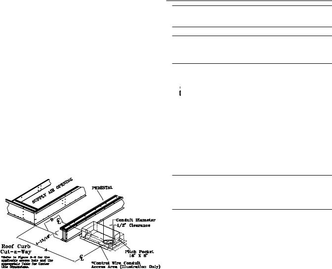
Trane's Engineering Bulletin RT-EB-80 provides additional information concerning duct design and sound reduction.
Pitch Pocket Location
The location of the main supply power entry for S_HF 20 through 75 Ton rooftop units is located at the bottom righthand corner of the control panel. Figures 3-2A, B & C illustrate the location for the electrical entrance through the base in order to enter the control panel. If the power supply conduit penetrates the building’s roof beneath this opening, it is recommended that a pitch pocket be installed before the unit is placed onto the roof curb. The center line dimensions shown in the illustration below indicates the center line of the electrical access hole in the unit base when it is positioned on the curb, ±3/8 inch. The actual diameter of the hole in the roof should be at least 1/2 inch larger than the diameter of the conduit penetrating the roof. This will allow for the clearance variable between the roof curb rail and the unit base rail illustrated in Figure 3-5.
The pitch pocket dimensions listed are recommended to enhance the application of roofing pitch after the unit is set into place. The pitch pocket may need to be shifted as illustrated to prevent interference with the curb pedestal.
Installation (Continued)
Note: If a “built-up” curb is provided by others, keep in mind that these commercial rooftop units do not have base pans in the condenser section.
Note: If this is a REPLACEMENT UNIT keep in mind that the CURRENT DESIGN commerical rooftop unitsdo not have base pans in the condenser section.
Unit Rigging & Placement


 WARNING
Heavy Objects!
Do not use cables (chains or slings) except as shown. Each of the cables (chains or slings) used to lift the unit must be capable of supporting the entire weight of the unit. Lifting cables (chains or slings) may not be of the same length. Adjust as necessary for even unit lift. Other lifting arrangements may cause equipment or property-only damage. Failure to properly lift unit may result in death or serious injury. See details below.
Unit |
Tonnage |
“A” Dimension |
"B" Dimension |
S*HF |
20, 25 & 30 |
4' 5-9/16" |
5-9/16" |
S*HF |
50 & 55 |
9' 5-11/16" |
5-1/2" |
S*HF |
40, 60, 70 & 75 |
6' 9-5/8" |
7-3/16" |
* = All unit functions (SAHF, SEHF, SFHF, SSHF, SLHF and SXHF)
If a Trane Curb Accessory Kit is not used:
a.The ductwork can be attached directly to the factory-provided flanges around the unit’s supply and return air openings. Be sure to use flexible duct connections at the unit.
b.For “built-up” curbs supplied by others, gaskets must be installed around the curb perimeter flange and the supply and return air opening flanges.
Note: Use spreader bars as shown in the diagram. Refer to the Installation manual or nameplate for the unit weight.Refer to the Installation Instructions located inside the side control panel for further rigging information.
1.A Center-of-Gravity illustration and the dimensional data is shown in Figure 3-3.
2.Attach adequate strength lifting slings to all four lifting lugs on 20 through 75 Ton units and to all six lifting lugs on 90 through 130 Ton units. The minimum distance between the lifting hook and the top of the unit should be 7 feet for 20 through 75 Ton units and 12 feet for 90 through 130 Ton units. Figure 3-4 illustrates the installation of spreader bars to protect the unit and to facilitate a uniform lift. Table 3-3 list the typical unit operating weights.
3.Test-lift the unit to ensure it is properly rigged and balanced, make any necessary rigging adjustments.
4.Lift the unit and position it over the curb and pedestal. (These units have a continuous base rail around the air handler section which matches the curb.
5.Align the base rail of the unit’s air handler section with the curb rail while lowering the unit onto the curb. Make sure that the gasket on the curb is not damaged while positioning the unit. (The pedestal simply supports the unit’s condenser section)
A cross section of the juncture between the unit and the roof curb is shown in Figure 3-5.
23
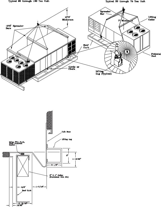
Figure 3-4
Typical Unit Rigging
Figure 3-5
Unit Base & Roof Curb Section
24

General Unit Requirements
The checklist listed below is a summary of the steps required to successfully install a Commercial rooftop unit. This checklist is intended to acquaint the installing personnel with what is required in the installation process. It does not replace the detailed instructions called out in the applicable sections of this manual.
[ ] Check the unit for shipping damage and material shortage; file a freight claim and notify Trane office.
[ ] Verify that the installation location of the unit will provide the required clearance for proper operation.
[ ] Assemble and install the roof curb. Refer to the current edition of SAHF-IN-5 for 20 through 75 Ton units or SXHG-IN-2 for 90 through 130 Ton units.
[ ] Fabricate and install ductwork; secure ductwork to curb.
[ ] Install pitch pocket for power supply through building roof. (If applicable)
[ ] Rigging the unit.
[ ] Set the unit onto the curb; check for levelness.
[ ] Ensure unit-to-curb seal is tight and without buckles or cracks.
[ ] Install and connect condensate drain lines to each evaporator drain connection.
[ ] Remove the shipping hardware from each compressor assembly.
[ ] Remove the shipping hold-down bolts and shipping channels from the supply and exhaust fans ordered with rubber or spring isolators.
[ ] Check all optional supply and exhaust fan spring isolators for proper adjustment.
[ ] Verify that all plastic coverings are removed from the compressors.
[ ] Verify all discharge and liquid line service valves (one per circuit) are back seated.
Main Electrical Power Requirements
[ ] Verify that the power supply complies with the unit nameplate specifications.
[ ] Inspect all control panel components; tighten any loose connections.
[ ] Connect properly sized and protected power supply wiring to a field-supplied/installed disconnect and unit
[ ] Properly ground the unit.
Note: All field-installed wiring must comply with NEC and applicable local codes.
Installation (Continued)
Field Installed Control Wiring
[ ] Complete the field wiring connections for the constant volume controls as applicable. Refer to "Field Installed Control Wiring" for guidelines.
[ ] Complete the field wiring connections for the variable air volume controls as applicable. Refer to "Field Installed Control Wiring" for guidelines.
Note: All field-installed wiring must comply with NEC and applicable local codes.
Requirements for Electric Heat Units
All SEHF Units (380 minimum voltage) & SEHG units.
[ ] Verify that the power supply complies with the electric heater specifications on the unit and heater nameplate.
[ ] Inspect the heater junction box and control panel; tighten any loose connections.
[ ] Check electric heat circuits for continuity.
SEHF Units w/200V or 230V Electric Heat: (Requires Separate Power Supply to Heater)
[ ] Connect properly sized and protected power supply wiring for the electric heat from a dedicated, fieldsupplied/ installed disconnect to terminal block 4TB2, or to an optional unit mounted disconnect switch 4S15.
Requirements for Gas Heat
[ ] Gas supply line properly sized and connected to the unit gas train.
[ ] All gas piping joints properly sealed.
[ ] Drip leg Installed in the gas piping near the unit.
[ ] Gas piping leak checked with a soap solution. If piping connections to the unit are complete, do not pressurize piping in excess of 0.50 psig or 14 inches w.c. to prevent component failure.
[ ] Main supply gas pressure adequate.
[ ] Flue Tubes clear of any obstructions.
[ ] Factory-supplied flue assembly installed on the unit.
[ ] Connect the 3/4" CPVC furnace drain stubout to a proper condensate drain.
Requirements for Hot Water Heat (SLH_)
[ ] Route properly sized water piping through the base of the unit into the heating section.
[ ] Install the factory-supplied, 3-way modulating valve.
[ ] Complete the valve actuator wiring.
25

Requirements for Steam Heat (SSH_)
[ ] Install an automatic air vent at the top of the return water coil header.
[ ] Route properly sized steam piping through the base of the unit into the heating section.
[ ] Install the factory-supplied, 2-way modulating valve
[ ] Complete the valve actuator wiring.
[ ] Install 1/2", 15-degree swing-check vacuum breaker(s) at the top of each coil section. Vent breaker(s) to theatmosphere or merge with return main at discharge side of steam trap.
[ ] Position the steam trap discharge at least 12" below the outlet connection on the coil.
Installation (Continued)
[ ] Use float and thermostatic traps in the system, as required by the application.
O/A Pressure Sensor and Tubing Installation
(All units with Statitrac)
[ ] O/A pressure sensor mounted to the roof bracket.
[ ] Factory supplied pneumatic tubing installed between the O/A pressure sensor and the connector on the vertical support.
[ ] Field supplied pneumatic tubing connected to the proper fitting on the space pressure transducer located in the filter section, and the other end routed to a suitable sensing location within the controlled space.
Figure 3-6A
Condensate Drain Locations
26
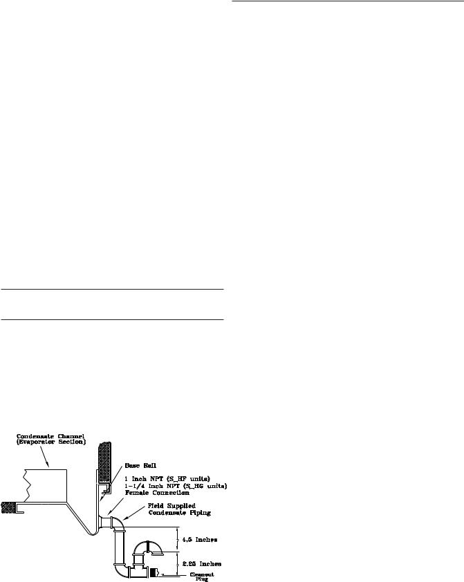
Condensate Drain Connections
Each S_HF unit is provided with two or six 1" evaporator condensate drain connections (one on each side of the unit). Each S_HG unit is provided with two or six 1-1/4" evaporator drain connections (one on each side of the unit.)
Due to the size of these units, all condensate drain connection must be connected to the evaporator drain connections. Refer to the appropriate illustration in Figure 3-2 for the location of these drain connections.
A condensate trap must be installed due to the drain connection being on the "negative pressure" side of the fan. Install the P-Traps at the unit using the guidelines in Figure 3- 6.
Pitch the drain lines at least 1/2 inch for every 10 feet of horizontal run to assure proper condensate flow. Do not allow the horizontal run to sag causing a possible double-trap condition which could result in condensate backup due to "air lock".
Units with Gas Furnace
Units equipped with a gas furnace have a 3/4" CPVC drain connection stubbed out through the vertical support in the gas heat section. It is extremely important that the condensate be piped to a proper drain. Refer to the appropriate illustration in Figure 3-2 for the location of the drain connection.
Note: Units equipped with an optional modulating gas furnace will likely operate in a condensing mode part of the time.
An additional 1-1/4" non-connectable water drain is located in the base rail within the heating section.
Ensure that all condensate drain line installations comply with applicable building and waste disposal codes.
Figure 3-6
Condensate Trap Installation
Shipping Fasteners
Removing Compressor Assembly Shipping Hardware (20 through 60 Ton)
Each manifolded compressor assembly is rigidly bolted to a mounting rail assembly. The rail assembly sets on four (4) rubber isolators. The assembly is held in place by two shipping braces that secure each compressor rail assembly to
Installation (Continued)
the unit's base rail. To locate and remove the shipping hardware, refer to Figure 3-7 and the following procedure.
1.Remove the four anchor bolts (2 front and 2 rear), used to secure the shipping brace to the unit's base rail (two assemblies on 40 through 60 Ton units).
2.Remove the three self-tapping screws that secure each shipping brace to the compressor mounting rails.
3.Remove and discard the two 30-1/2" long shipping braces for each assembly.
4.Do not remove the shipping bracket located on top of the compressors.
5.Ensure that the compressor rail assembly is free to move on the rubber isolators.
Removing Compressor Assembly Shipping Hardware (70 & 105 Ton)
Each manifolded compressor assembly is rigidly bolted to a mounting rail assembly. The rail assembly sets on six (6) rubber isolators. The assembly is held in place by four (4) shipping "Tiedown" bolts. To remove the shipping hardware, follow the procedures below:
1.At each "Tiedown" location (2 front and 2 rear), remove and discard the tiedown bolt and the slotted shipping spacer located between the compressor rails and the unit base rail illustrated in Figure 3-7B, "Tiedown Bolt" detail.
2.Remove the bolt in each rubber isolator and the slotted shipping spacer located between the compressor rails and the unit base rail illustrated in Figure 3-7B, "Isolator Bolt" detail. Reinstall the bolts at the same location by screwing them into the base rail two to three turns only.
3.Ensure that the compressor rail assembly is free to move on the rubber isolators.
Removing Compressor Assembly Shipping Hardware (115 and 130 Ton)
Each manifolded compressor assembly is rigidly bolted to a mounting rail assembly. The rail assembly sets on eight (8) rubber isolators. The assembly is held in place by six (6)
"Tiedown Bolts". To remove the shipping hardware, follow the procedure below:
1.At each "Tiedown" location (6), remove and discard the tiedown bolt and the slotted shipping spacer located between the compressor rails and the unit base rail illustrated in Figure 3-7C, "Tiedown Bolt" detail.
2.Remove the bolt in each rubber isolator and the slotted shipping spacer located between the compressor rails and the unit base rail illustrated in Figure 3-7C, "Isolator Bolt" detail. Reinstall the bolts at the same location by screwing them into the base rail two to three turns only.
3.Ensure that the compressor rail assembly is free to move on the rubber isolators.
27

Figure 3-7A
Removing Scroll Compressor Shipping Hardware for 20 through 60 Ton Units
Figure 3-7B
Removing Scroll Compressor Shipping Hardware for 70 through 105 Ton Units
Figure 3-7C
Removing Scroll Compressor Shipping Hardward for 115 and 130 Ton Units
28

Removing Supply and Exhaust Fan Shipping Channels (Motors >5Hp)
Each supply fan assembly and exhaust fan assembly for S_HF units shipped with a motor larger than 5 HP is equipped with rubber isolators, (as standard), or optional spring isolators. Each supply fan assembly and exhaust fan assembly for S_HG units is equipped with spring isolators. Shipping channels are installed beneath each fan assembly and must be removed. To locate and remove these channels, refer to Figure 3-8 and use the following procedures.
Rubber Isolators:
1.Remove and discard the shipping bolts from the fan assembly rails.
Installation (Continued)
2.Elevate the fan-and-motor assembly and slide the shipping channels out from between the fan assembly rails and the unit's base rail.
3.Lower the fan-and-motor assembly onto the isolators. Make sure that the pins at the top of the isolators are engaged in the corresponding holes on the fan assembly.
4.Verify that the fan assembly is being supported by the isolators.
Spring Isolators:
Spring isolators for the supply and/or exhaust fan are shipped with the isolator adjusting bolt backed out. Field adjustment is required for proper operation. Figure 3-8 shows isolator locations. To adjust the spring isolators use the following procedure.
1.Remove and discard the shipping tie down bolts but leave the shipping channels in place during the adjustment procedure. See Figure 3-8.
2.Tighten the leveling bolt on each isolator until the fan assembly is approximately 1/4" above each shipping channel.
3.Secure the lock nut on each isolator.
4.Remove the shipping channels and discard.
29
 Loading...