


 Loading...
Trane GER-036, GER-048, GER-060, GER-072, GER-090 Installation and Maintenance Manual
...Installation, Operation,
and Maintenance
Water-Source Comfort System
Axiom™ Rooftop
Models |
“E” and later Design Sequence |
60HZ |
GER -036, -048, -060, -072, -090, -120, -150, -180, -240,-300 |
 SAFETY WARNING
Only qualified personnel should install and service the equipment. The installation, starting up, and servicing of heating, ventilating, and airconditioning equipment can be hazardous and requires specific knowledge and training. Improperly installed, adjusted or altered equipment by an unqualified person could result in death or serious injury. When working on the equipment, observe all precautions in the literature and on the tags, stickers, and labels that are attached to the equipment.
August 2013 |
WSHP-SVX12B-EN |
Warnings, Cautions and Notices
Warnings, Cautions and Notices. Note that warnings, cautions and notices appear at appropriate intervals throughout this manual. Warnings are provide to alert installing contractors to potential hazards that could result in death or personal injury. Cautions are designed to alert personnel to hazardous situations that could result in personal injury, while notices indicate a situation that could result in equipment or property-damage-only accidents.
Your personal safety and the proper operation of this machine depend upon the strict observance of these precautions.
Read this manual thoroughly before operating or servicing this unit.
ATTENTION: Warnings, Cautions, and Notices appear at appropriate sections throughout this literature. Read these carefully:
 WARNING
 CAUTIONs
NOTICE:
Indicates a potentially hazardous situation which, if not avoided, could result in death or serious injury.
Indicates a potentially hazardous situation which, if not avoided, could result in minor or moderate injury. It could also be used to alert against unsafe practices.
Indicates a situation that could result in equipment or property-damage only accidents.
Important
Environmental Concerns!
Scientific research has shown that certain man-made chemicals can affect the earth’s naturally occurring stratospheric ozone layer when released to the atmosphere. In particular, several of the identified chemicals that may affect the ozone layer are refrigerants that contain Chlorine, Fluorine and Carbon (CFCs) and those containing Hydrogen, Chlorine, Fluorine and Carbon (HCFCs). Not all refrigerants containing these compounds have the same potential impact to the environment.Trane advocates the responsible handling of all refrigerants-including industry replacements for CFCs such as HCFCs and HFCs.
Responsible Refrigerant Practices!
Trane believes that responsible refrigerant practices are important to the environment, our customers, and the air conditioning industry. All technicians who handle refrigerants must be certified.The Federal Clean Air Act (Section 608) sets forth the requirements for handling, reclaiming, recovering and recycling of certain refrigerants and the equipment that is used in these service procedures. In addition, some states or
municipalities may have additional requirements that must also be adhered to for responsible management of refrigerants. Know the applicable laws and follow them.
 WARNING
Proper Field Wiring and Grounding
Required!
All field wiring MUST be performed by qualified personnel. Improperly installed and grounded field wiring poses FIRE and ELECTROCUTION hazards. To avoid these hazards, you MUST follow requirements for field wiring installation and grounding as described in NEC and your local/state electrical codes. Failure to follow code could result in death or serious injury.
 WARNING
Personal Protective Equipment (PPE)
Required!
Installing/servicing this unit could result in exposure to electrical, mechanical and chemical hazards.
•Before installing/servicing this unit, technicians MUST put on all Personal Protective Equipment (PPE) recommended for the work being undertaken. ALWAYS refer to appropriate MSDS sheets and OSHA guidelines for proper PPE.
•When working with or around hazardous chemicals, ALWAYS refer to the appropriate MSDS sheets and OSHA guidelines for information on allowable personal exposure levels, proper respiratory protection and handling recommendations.
•If there is a risk of arc or flash, technicians MUST put on all Personal Protective Equipment (PPE) in accordance with NFPA 70E or other country-specific requirements for arc flash protection, PRIOR to servicing the unit.
Failure to follow recommendations could result in death or serious injury.
 WARNING
Contains Refrigerant!
System contains oil and refrigerant under high pressure. Recover refrigerant to relieve pressure before opening the system. See unit nameplate for refrigerant type. Do not use non-approved refrigerants, refrigerant substitutes, or refrigerant additives.
Failure to follow proper procedures or the use of nonapproved refrigerants, refrigerant substitutes, or refrigerant additives could result in death or serious injury or equipment damage.
© 2013Trane All rights reserved |
WSHP-SVX12B-EN |
Warnings, Cautions and Notices
 WARNING
Hazardous Voltage w/Capacitors!
Disconnect all electric power, including remote disconnects and discharge all motor start/run capacitors before servicing. Follow proper lockout/ tagout procedures to ensure the power cannot be inadvertently energized. Verify with an appropriate voltmeter that all capacitors have discharged. Failure to disconnect power and discharge capacitors before servicing could result in death or serious injury.
 WARNING
Fiberglass Wool!
Product contains fiberglass wool. Disturbing the insulation in this product during installation, maintenance or repair will expose you to airborne particles of glass wool fibers and ceramic fibers known to the state of California to cause cancer through inhalation. Glass wool fibers may also cause respiratory, skin or eye irritation.
NOTICE:
Equipment Damage From Ultraviolet
(UV) Lights!
The manufacturer does not recommend field installation of ultraviolet lights in its equipment for the intended purpose of improving indoor air quality. High intensity C-band ultraviolet light is known to severely damage polymer (plastic) materials and poses a personal safety risk to anyone exposed to the light without proper personal protective equipment. Polymer materials commonly found in HVAC equipment that may be susceptible include insulation on electrical wiring, fan belts, thermal insulation, various fasteners and bushings. Degradation of these materials can result in serious damage to the equipment.
The manufacturer accepts no responsibility for the performance or operation of our equipment in which ultraviolet devices were installed outside of the manufacturer’s factory or its approved suppliers.
Introduction
Revision Summary.
WSHP-SVX12B-EN
Corrected dimensions and added center of gravity information.
Trademarks
Axiom, Precedent, ReliaTel,TOPSS,Tracer, Voyager II, Trane, and theTrane logo are trademarks or registered trademarks ofTrane in the United States and other countries.Trane is a business of Ingersoll Rand. All trademarks referenced in this document are the trademarks of their respective owners.
LonTalk is a registered trademark of Echelon Corporation.
WSHP-SVX12B-EN |
3 |

Table of Contents |
|
Warnings, Cautions and Notices . . . . . . |
. . . . 2 |
Introduction . . . . . . . . . . . . . . . . . . . . |
. . . . 3 |
Model Number Descriptions . . . . . . . . . . |
. . . . 5 |
General Information . . . . . . . . . . . . . . . . . |
. . . . 6 |
Jobsite Inspection . . . . . . . . . . . . . . . |
. . . . 6 |
Jobsite Storage . . . . . . . . . . . . . . . . . |
. . . . 6 |
Unit Description . . . . . . . . . . . . . . . . . |
. . . . 6 |
System Input Devices and Functions |
. . . . 6 |
Field installed ONLY Accessories . . . |
. . . . 8 |
Component Location . . . . . . . . . . . . . |
. . . . 9 |
Dimensions . . . . . . . . . . . . . . . . . . . . . . . . . |
. . . 10 |
Unit Clearances . . . . . . . . . . . . . . . . . |
. . . 10 |
Installation . . . . . . . . . . . . . . . . . . . . . . . . . . |
. . . 30 |
General Installation Checks . . . . . . . . |
. . . 30 |
Main Electrical Power Requirements |
. . . 30 |
Foundation for Rooftop Units . . . . . . |
. . . 30 |
Ductwork . . . . . . . . . . . . . . . . . . . . . . . |
. . . 31 |
Roof Curbs . . . . . . . . . . . . . . . . . . . . . |
. . . 31 |
Rigging the Unit . . . . . . . . . . . . . . . . . |
. . . 31 |
Supply/Return Pipe . . . . . . . . . . . . . . |
. . . 31 |
Drain Connection . . . . . . . . . . . . . . . . |
. . . 32 |
Horizontal Discharge Conversion . . . |
. . . 32 |
TCO-A Instructions . . . . . . . . . . . . . . . |
. . . 33 |
Field Installed Power Wiring . . . . . . . |
. . . 34 |
Field Installed Control Wiring . . . . . . |
. . . 34 |
Control Power Transformer . . . . . . . . |
. . . 34 |
Electrical Requirements . . . . . . . . . . . . . . |
. . . 38 |
Pre-Start . . . . . . . . . . . . . . . . . . . . . . . . . . . . |
. . . 45 |
Space Temperature Averaging . . . . . |
. . . 45 |
Test Modes . . . . . . . . . . . . . . . . . . . . . |
. . . 47 |
Pre-Startup Checklist . . . . . . . . . . . . . |
. . . 52 |
Start Up . . . . . . . . . . . . . . . . . . . . . . . . . . . . |
. . . 53 |
Initial Unit Start-up . . . . . . . . . . . . . . . |
. . . 53 |
Water Pressure Drop . . . . . . . . . . . . . |
. . . 54 |
Maintenance . . . . . . . . . . . . . . . . . . . . . . . . |
. . . 55 |
Preventive Maintenance . . . . . . . . . . |
. . . 55 |
Troubleshooting . . . . . . . . . . . . . . . . . . . . . |
. . . 56 |
Warranty . . . . . . . . . . . . . . . . . . . . . . . . . . . . |
. . . 58 |
Standard Warranty . . . . . . . . . . . . . . . . . . .58
Extended Warranty . . . . . . . . . . . . . . . . . .58
4 |
WSHP-SVX12B-EN |

Model Number Descriptions
G |
|
E |
|
R |
|
E |
060 |
1 |
1 |
|
A |
0 |
1 |
1 |
0 |
|
D |
0 |
|
T |
0 |
|
A |
6 |
0 |
0 |
|
1 1 0 A |
0 |
|
B |
0 |
0 0 0 0 000 |
|||||||||||||||||
|
|
|
|
|
|
|
|
|
|
|
|
|
|
|
|
|
|
|
|
|
|
|
|
|
|
|
|
|
|
|
|
|
|
|
|
|
|
|
|
|
|
|
|
|
|
|
|
|
|
|
1 |
2 |
3 |
4 |
5,6,7 |
8 |
9 |
10 |
11 |
12 |
13 |
14 |
15 |
16 |
17 |
18 |
19 |
20 |
21 |
22 |
23 24 25 26 |
27 |
28 |
29 |
30-36 |
||||||||||||||||||||||||||
Digits 1-3 — Unit Configuration
GER= High Efficiency Rooftop
Digit 4 — Development
Sequence
E
Digits 5-7 — Nominal Size (MBH)
036 = |
3Ton |
048 = |
4Ton |
060 = |
5Ton |
072 = |
6Ton |
090 = |
7 1/2Ton |
120 = |
10Ton |
150 = |
12 1/2Ton |
180 = |
15Ton |
240 = |
20Ton |
300 = |
25Ton |
Digit 8 — Voltage (Volts/Hz/
Phase)
1 |
= |
208/60/1 |
2 |
= |
230/60/1 |
3 |
= |
208/60/3 |
4 |
= |
460/60/3 |
5 |
= |
575/60/3 |
8 |
= |
230/60/3 |
Digit 9 — Heat Exchanger
1= Copper Water Coil
2= Cupro-nickel Water Coil
Digit 10 — Design Sequence
Most Up-to-Date Design
Digit 11 — Refrigeration Circuit
0 |
= |
Heating and Cooling Circuit |
A |
= |
Cooling ONLY Circuit |
Digit 12 — Blower Configuration
1= Standard Blower
2= Oversized Blower Motor
Digit 13 — Freeze Protection
A= 20 Degree Freezestat B/T
B= 30 Degree Freezestat B/T
Digit 14 — Open Digit
0 |
= |
Standard Design |
S |
= |
Design Special |
Digit 15 — Supply-Air
Arrangement
D= Down-Flow Supply-Air Arrangement (convertible for 3 - 10Ton)
H= Horizontal Supply-Air Arrangement
(12 1/2 - 25Ton option)
DIGIT 16 — Return-Air
Arrangement
0 = Standard Return-Air
Arrangement
Digit 17 — Control Types
R |
= |
ReliaTel™ Standalone Controls |
T |
= |
Tracer™ Communication |
|
|
Interface |
L= LonTalk™ Communication Interface
Digit 18 — T’stat/Sensor
Location
0 = Wall Mounted Location
A= Wall Mounted Sensor with Unit Mounted Return-Air Smoke Detector
B= Wall Mounted Sensor with Unit
Mounted Supply-Air Smoke Detector
C= Wall Mounted Sensor with Unit Mounted Return-Air/Supply-Air Smoke Detectors
Digit 19 — Fault Sensors
0 = No Fault Sensor
A= Clogged Filter Switch
B= Fan Failure Switch
C= Discharge Air SensingTube
D= Clogged Filter Switch and Fan
Fail
Switch
E= Clogged Filter Switch and Discharge Air SensingTube
F= Fan Fail Switch and Discharge Air SensingTube
G= Clogged Filter Switch, Fan Fail Switch and DA SensingTube
Digit 20 — Temperature Sensor
7= High Pressure Control/Frostat/ Crankcase Heater
Digit 21 — Night Setback
0 |
= |
No Night Setback Relay |
N |
= |
Night Setback Relay |
Note: Option N is used for the Micro
Standalone Controller ONLY.
Digit 22 — Electric Heat Option
0 = No Electric Heat
A= 5 kW (1-Phase)
B= 6 kW (3-Phase)
C= 9 kW (3-Phase)
D= 10 kW (1-Phase)
E= 12 kW (3-Phase)
F= 14 kW (1-Phase)
G= 18 kW (1 and 3-Phase)
J= 23 kW (3-Phase)
K= 27 kW (3-Phase)
N |
= |
36 kW (3-Phase) |
P |
= |
54 kW (3-Phase) |
Digit 23 — Unit Mounted
Disconnect
0= No Unit Mounted Disconnect
1= Non-Fused Disconnect
2= Circuit Breaker
Digit 24 — Filter Type
2 |
= |
2"Throwaway Filter |
4 |
= 2" MERV 8 Filter |
|
5 |
= |
2" MERV 13 Filter |
Digit 25 |
— Acoustic |
||
|
|
Arrangement |
|
0 |
= |
Sound Attenuation Package |
|
Digit 26 |
— Factory |
||
Configuration |
|||
0 |
= |
Standard Factory Configuration |
|
A |
= |
Hinged Access Panels |
|
Digit 27 |
— Paint Color |
||
0 |
= |
No Paint Selection Available |
|
Digit 28 |
— Outside Air Option |
||
0 |
= |
No Outside Air |
|
A= Manual Outside Air Damper 0-25%
B= Motorized Outside Air Damper 0-50%
C= Economizer, Dry Bulb 0-100% without Barometric Relief
D= Economizer, Dry Bulb 0-100% with Barometric Relief
E= Economizer, Reference Enthalpy 0-100% without Barometric
Relief
F= Economizer, Reference Enthalpy 0-100% with Barometric Relief
G= Economizer, Comparative Enthalpy 0-100%
without Barometric Relief
H= Economizer, Comparative Enthalpy 0-100%
with Barometric Relief
Digit 29 — Piping Arrangement
0 = Standard Piping Configuration
Digits 30-36 — Does Not Apply
To The Rooftop Product
0000000= Digit 30-36 Does NOT Apply to
the Rooftop Products
Note: Through-the-base electric is a standard feature on the watersource rooftop unit.
WSHP-SVX12B-EN |
5 |

General Information
Jobsite Inspection
Always perform the following checks before accepting a unit:
•Verify that the nameplate data matches the data on the sales order and bill of lading (including electrical data).
•Verify that the power supply complies with the unit nameplate specifications.
•Visually inspect the exterior of the unit, for signs of shipping damage. Do not sign the bill of lading accepting the unit(s) until inspection has been completed. Check for damage promptly after the unit(s) are unloaded. Once the bill of lading is signed at the jobsite, the unit(s) are now the property of the SOLDTO party and future freight claims MAY NOT be accepted by the freight company.
•After assuring that charge has been retained, reinstall the schrader caps to assure that refrigerant leakage does not occur.
•After assuring that charge has been retained, reinstall the schrader caps to assure that refrigerant leakage does not occur.
•Verify that the refrigerant charge has been retained during shipment by use of gauges. Schrader taps are located internal to the cabinet.
•After assuring that charge has been retained, reinstall the schrader caps to assure that refrigerant leakage does not occur.
Jobsite Storage
Take precautions to prevent condensate from forming inside the unit’s electrical compartments and motors if:
•If the unit is stored before it is installed.
•The unit is set on the roof curb, and temporary heat is provided in the building. Isolate all side panel service entrances and base pan openings (e.g. conduit holes, supply air/return air openings, and flue openings) from the ambient air until the unit is ready for start-up.
The manufacturer will not assume any responsibility for equipment damage resulting form condensate accumulation on the unit’s electrical and/or mechanical components.
Unit Description
Before shipment, each unit is leak tested, dehydrated, charged with refrigerant and compressor oil, and run tested for proper control operation.
Unit Nameplate
The unit nameplate is located on the units’s corner support just above the main power entrance access into the control panel. It includes the unit model number, serial number,
electrical characteristics, refrigerant charge, and other pertinent unit data.
Compressor Nameplate
The nameplate for the compressors are located on the compressor terminal box.
Air-to-Refrigerant Coil
The air-to-refrigerant coil is aluminum fin, mechanically bonded to the copper tubing.
Water-to-Refrigerant Coil
The water-to-refrigerant coil is a copper or cupro-nickel (option) and steel tube (tube-within-a-tube) design, leak tested to assure there is no cross leakage between the water tube (copper/cupro-nickel) and refrigerant gas (steel tube).
The control system offered to control the unit is a ReliaTel™ Control Module. It may be installed as a standalone unit control module, or tied to a full building automation system.
The ReliaTel™ Control Module is a microelectronic control module that is referred to as a Refrigeration Module (RTRM).The acronym RTRM is used extensively throughout this document when referring to the control system network.
These modules through Proportional/Integral control algorithms perform specific unit functions that govern unit operation in response to zone temperature, supply air temperature and/or humidity conditions depending on the application.The stages of capacity control for these units is achieved by starting and stopping the compressors.
The RTRM is mounted in the control panel and is factory wired to the respective internal components. RTRM receives and interprets information from other unit modules, sensors, remote panels and customer binary contacts to satisfy the applicable request for cooling.
System Input Devices and Functions
The RTRM must have a mode input in order to operate the rooftop unit.The flexibility of having several mode capabilities depends upon the type of sensor and/or remote panel selected to interface with the RTRM.The possibilities are; Fan selection ON or AUTO, System selection HEAT, COOL, AUTO, and OFF.
The descriptions of the following basic input devices used with the RTRM network are to acquaint the operator with their function as they interface with the various modules. Refer to the unit’s electrical schematic for the specific module connections.
Compressor Disable (CPR1/2)
This input incorporates the low (LPC) of each refrigeration circuit and can be activated by opening a field supplied contact installed in series with the LPC.
6 |
WSHP-SVX12B-EN |

General Information
If this circuit is open before the compressor is started, the compressor will not be allowed to operate. Anytime this circuit is opened for 5-continuous seconds during compressor operation, the compressor for that circuit is immediately turned OFF.The compressor will not be allowed to restart for a minimum of 3-minutes should the LPC close.
If four consecutive open conditions occur during the first 3-minutes of operation, the compressor for that circuit will be locked out, a diagnostic communicated to the remote panel (if installed) and a manual reset will be required to restart the compressor.
Low Pressure Control
With the ReliaTel module, the low pressure will be activated when a field supplied contact is opened. Anytime this circuit is opened for 5-continuous seconds, the compressor for that circuit is turned off immediately. The compressor will not be allowed to restart for a minimum of 3-minutes.
If four consecutive open conditions occur during the first 3-minutes of operation, the compressor will be locked out, a diagnostic communicated to ICSTM if applicable, and a manual reset will be required to restart the compressor.
High Pressure Control
The high pressure controls are wired in series between the compressor outputs on the RTRM and the compressor contactor coils. If the high pressure control switch opens, the RTRM senses a lack of current while calling for cooling and locks the compressor out.
On dual circuit units, if the high pressure control opens, the compressor on the affected circuit is locked out. A manual reset for the affected circuit is required.
Economizer Control Actuator ECA (option)
The ECA monitors the mixed-air temperature, return air temperature, minimum position setpoint (local or remote), power exhaust setpoint, CO2 setpoint, CO2 and ambient dry bulb/enthalpy sensor or comparative humidity (return air humidity against ambient humidity) sensors, if selected, to control dampers to an accuracy of
± 5% of stroke.The actuator is spring returned to the closed position any time power is lost to the unit. It is capable of delivering up to 25-inch pounds of torque and is powered by 24 VAC.
RTCI-ReliaTel Trane Communication Interface (option)
This module is used when the application calls for an ICS building management type control system. It allows the control and monitoring of the system through an ICS panel.The module can be ordered from the factory or ordered as a kit to be field installed. Follow the installation instruction that ships with each kit when field installation is necessary.
RTLI-ReliaTel LonTalk Communication
Interface (option)
This module is used when the application calls for either an ICS building management type control system that is LonTalk. It allows the control and monitoring of the system through an ICS panel.The module can be ordered from the factory or ordered as a kit to be field installed. Follow the installation instruction that ships with each kit when field installation is necessary.
RTOM-ReliaTel Options Module (option)
The RTOM monitors the supply fan proving, clogged filter, supply air temperature, exhaust fan setpoint, supply air tempering, FrostatTM and smoke detector. Refer to system input devices and functions for operation.
Supply Fan Failure Input (option)
The fan failure switch can be factory or field installed to sense indoor fan operation. With the FFS-Fan Failure Switch, if air flow through the unit is not proven by the differential pressure switch (factory set point 0.07-inch w.c.) within 40-seconds nominally, the RTRM will shut off all mechanical operations, lock the system out, send a diagnostic to ICS, and the service LED will flash.The system will remain locked out until a reset is initiated either manually or through ICS.
Clogged Filter Switch (option)
The unit mounted clogged filter switch monitors the pressure differential across the return air filters. It is mounted in the filter section and is connected to the RTOM. A diagnostic service signal is sent to the remote panel if the pressure differential across the filters is at least 0.5-inch w.c.The contacts will automatically open when the pressure differential across the filters decreases to approximately 0.4-inch w.c.The clogged filter output is energized when the supply fan is operating and the clogged filter switch has been closed for at least 2- minutes.The system will continue to operate regardless of the status of the filter switch.
Power Exhaust Control (option)
The power exhaust fan is started whenever the position of the economizer dampers meets or exceed the power exhaust setpoint when the indoor fan is on.The setpoint panel is located in the return air section, and is factory set to 25%.
Evaporator Frost Control (option)
This input incorporates the Frostat control (FOS) of each refrigeration circuit and can be activated by closing a field supplied contact installed in parallel with the FOS.
If this circuit is open before the compressor is started, the compressor will not be allowed to operate. Anytime this circuit is opened for 5-continuous seconds during compressor operation, the compressor for that circuit is immediately turned OFF.The compressor will not be
WSHP-SVX12B-EN |
7 |

General Information
allowed to restart for a minimum of 3-minutes should the |
Zone Panel (BAYSENS108A) |
|
FOS close. |
This electronic sensor features four system switch settings |
|
Smoke Detector Sensor (option) |
||
(HEAT, COOL, AUTO, OFF) and two fan settings (ON and |
||
This sensor provides high limit shutdown of the unit and |
AUTO). It is a manual or auto changeover control with dual |
|
setpoint capability. It can be used with a remote zone |
||
requires a manual reset.The sensor is used to detect |
||
temperature sensor BAYSENS017B. |
||
smoke due to fire in the air conditioning or ventilation |
||
Remote Panel w/o NSB (BAYSENS110A) |
||
ducts. |
||
In order for the supply air smoke detector or return air |
This electronic sensor features four system switch settings |
|
smoke detector to properly sense smoke in the supply/ |
(HEAT, COOL, AUTO, and OFF) and two fan settings (ON |
|
return air stream, the air velocity entering the smoke |
and |
|
detector unit must be between 500 and 4000-feet per |
AUTO) with four system status LED’s. It is a manual or auto |
|
minute. |
||
changeover control with dual setpoint capability. It can be |
||
Discharge Line Thermostat |
||
used with a remote zone temperature sensor |
||
A bi-metal element discharge line thermostats installed as |
BAYSENS017B. |
|
Programmable Zone Sensor (BAYSENS019B) |
||
a standard option on the discharge line of each system. |
||
This standard option provides extra protection to the |
This 7-day programmable sensor features 2, 3, and 4- |
|
compressors against high discharge temperatures in case |
||
periods for Occupied/Unoccupied programming per day. |
||
of loss of charge, extremely high ambient and other |
||
If the power is interrupted, the program is retained in |
||
conditions which could drive the discharge temperature |
||
permanent memory. If power is off longer than 2-hours, |
||
higher. |
||
only the clock and day may have to be reset. |
||
|
Field installed ONLY Accessories
High Temperature Sensor (BAYFRST002A)
This sensor connects the RTRM Emergency Stop Input LTB1-5 and LTB1-6 and provides high limit shutdown of the unit and requires a manual reset.The sensor is used to detect high temperatures due to fire in the air conditioning or ventilation ducts.The sensor is designed to mount directly to the sheet metal duct. Each kit contains two sensors.The return air duct sensor (X13100040010) is set to open at 135-degrees F.The supply air duct sensor (X13100040020) is set to open at 240-degrees F.The control can be reset after the temperature has been lowered approximately 25-degrees F below the cutout setpoint.
Electronic Timeclock (BAYCLCK001A)
This electronic timeclock is designed to control the occupied/unoccupied switching of up to four rooftop units. Once the unit(s) has entered an unoccupied status, night setback temperatures can be controlled by utilizing a standard zone sensor wired to the RTRM.The timeclock contains four binary outputs (RE1, RE2, RE3, RE4), a liquid crystal display (LCD), and four programming keys (Time/ Day Key, Occupied/Unoccupied Program Key, Run Key, and an Advance/Override Key). An 18 to 30-VAC power source is required either from one of the units being controlled or from a separate class-2 power source.
Zone Panel (BAYSENS106A)
This electronic sensor features three system switch settings (EM HEAT, HEAT, COOL, and OFF) and two fan settings (ON and AUTO). It is a manual changeover control with single setpoint capability.
The zone sensor allows selection of 2, 3, and 4 system modes (HEAT, COOL, AUTO, and OFF), two fan modes (ON and AUTO) It has dual temperature selection with programmable start time capability.
The occupied cooling setpoint ranges between 45 and 98degrees F.The heating setpoint ranges between 43 and 96degrees F.
A liquid crystal display (LCD) displays zone temperature, temperature set points, day of the week, time, and operational mode symbols.
The option menu is used to enable or disable applicable functions, (i.e. morning warm-up, economizer minimum position override during unoccupied status, fahrenheit or centigrade, supply air tempering, remote zone temperature sensor, 12/24-hour time display, smart fan, and computed recovery.
During an occupied period, an auxiliary relay rated for 1.25-amps at 30-volts AC with one set of single pole, double throw contacts is activated.
Remote Zone Sensor (BAYSENS013C)
This electronic sensor features remote zone sensing and timed override with override cancellation. It is used with a Trane Integrated ComfortTM building management system.
Remote Zone Sensor (BAYSENS014C)
This electronic sensor features single setpoint capability and timed override with override cancellation. It is used with aTrane Integrated ComfortTM building management system.
8 |
WSHP-SVX12B-EN |
General Information
Remote Zone Sensor (BAYSENS016A)
This bullet type temperature sensor can be used for outside-air ambient sensing, return air temperature sensing, supply air temperature sensing, remote temperature sensing (uncovered).Wiring procedures vary according to the particular application and equipment involved. Refer to the unit’s wiring diagrams for proper connections.
Remote Zone Sensor (BAYSENS017B)
This electronic sensor can be used with BAYSENS106A, 108A, 110A, 019A, 020A, or 021A remote panels.When this sensor is wired to a BAYSENS019A or BAYSENS020A
remote panel, wiring must be 18 AWG shielded twisted pair (Belden 8760 or equivalent). Refer to the specific remote panel for wiring details.
Component Location
1.Controls
2.Compressor/water-to-refrigerant section
3.Air-to-refrigerant coil
4.Filter location
5.Blower and motor location
WSHP-SVX12B-EN |
9 |
Dimensions
Unit Clearances
10 |
WSHP-SVX12B-EN |
Dimensions
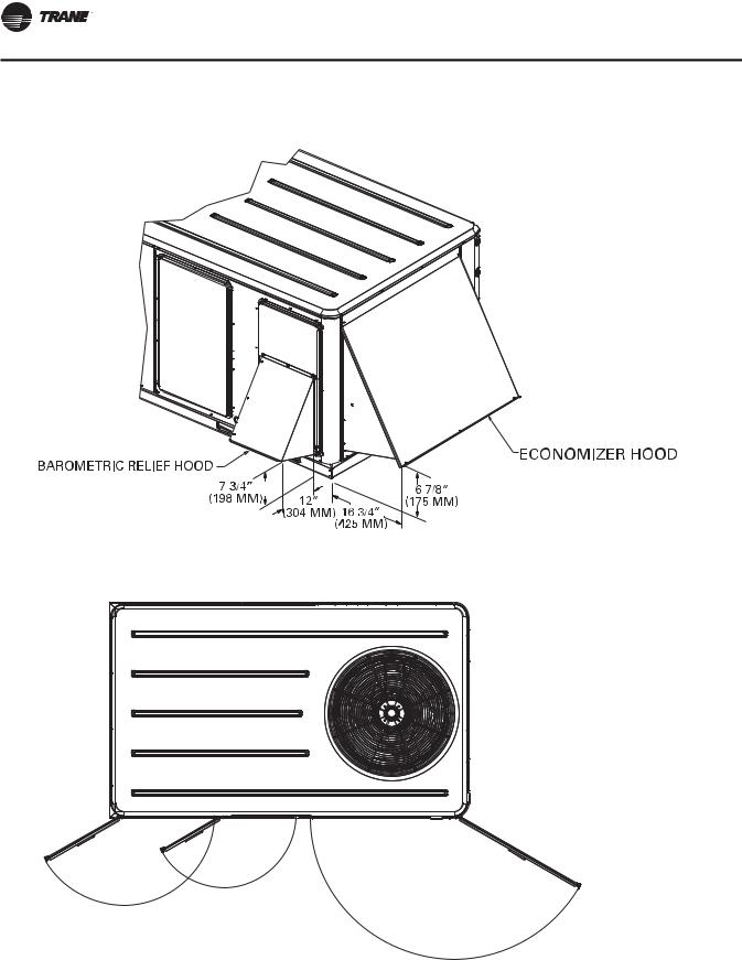
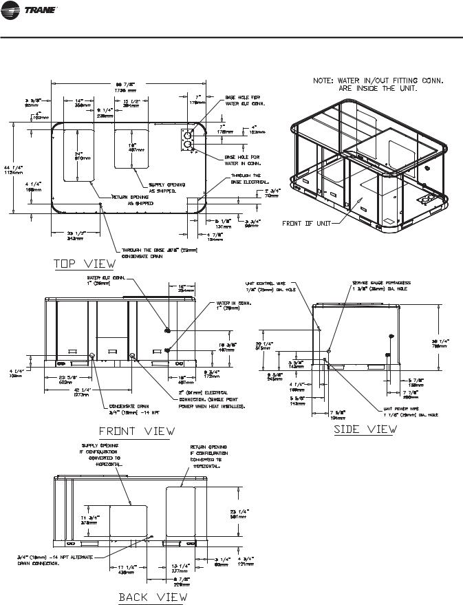
Figure 1. 036 to 048 Clearances
3-4 tons economizer, manual or motorized fresh air damper
Note: All dimensions are in inches/millimeters.
3-4 tons - swing diameter for hinged door(s) option
Note: All dimensions are in inches/millimeters.
17 7/8" 
 (448 MM)
3-4 tons - economizer & barometric relief damper hood
Note: All dimensions are in inches/millimeters.
16"
(406 MM) 22 1/4"
(565 MM)
WSHP-SVX12B-EN |
11 |
Dimensions
Figure 2. 060 to 072 Clearances
5-6 tons - economizer, manual or motorized fresh air damper
Note: All dimensions are in inches/millimeters.
5-6 tons - swing diameter for hinged door(s) option
Note: All dimensions are in inches/millimeters.
|
17” |
21 3/8” |
(432 MM) |
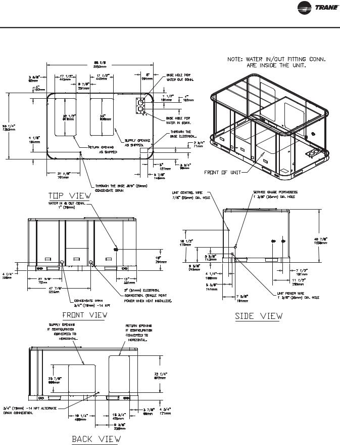
(543 MM) |
34 5/8” |
|
(879 MM)
12 |
WSHP-SVX12B-EN |
Dimensions
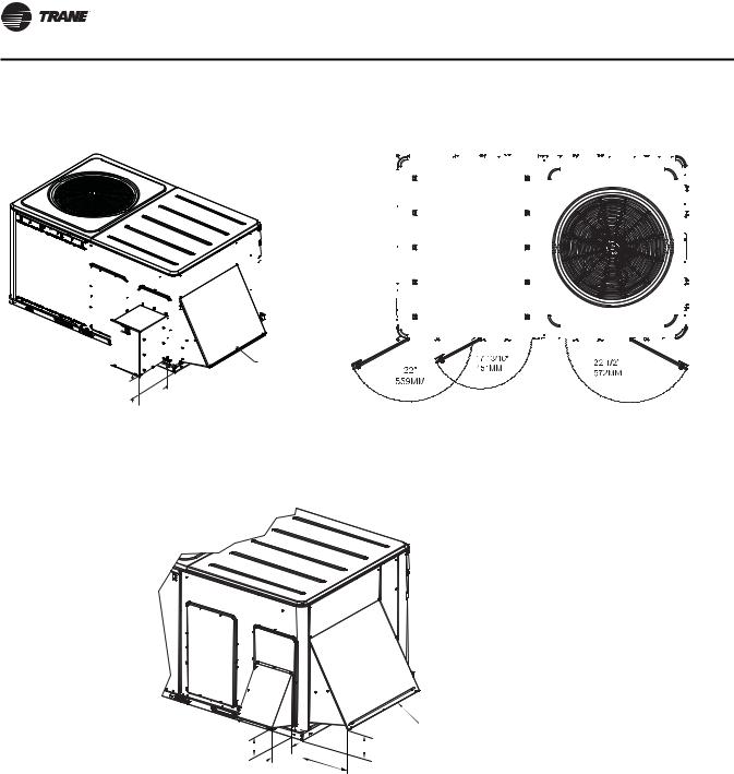
Figure 3. 090 Clearances
7½ tons power exhaust
Note: All dimensions are in inches/millimeters.
7½ tons swing diameter for hinged door(s) option
Note: All dimensions are in inches/millimeters.
|
17" |
21 3/8" |
432 MM |
543 MM |
34 5/8" |
|
879 MM |
7½ tons manual or motorized fresh air damper
Note: All dimensions are in inches/millimeters.
WSHP-SVX12B-EN |
13 |
Dimensions
Figure 4. 120 Clearances
|
|
|
|
10 tons exhaust |
|
10 tons swing diameter for hinged door(s) option |
||||||||||||||||||||||||||||||||||||||||||||
Note: All dimensions are in inches/millimeters. |
|
|
|
|
|
Note: All dimensions are in inches/millimeters. |
||||||||||||||||||||||||||||||||||||||||||||
|
|
|
|
|
|
|
|
|
|
|
|
|
|
|
|
|
|
|
|
|
|
|
|
|
|
|
|
|
|
|
|
|
|
|
|
|
|
|
|
|
|
|
|
|
|
|
|
|
|
|
|
|
|
|
|
|
|
|
|
|
|
|
|
|
|
|
|
|
|
|
|
|
|
|
|
|
|
|
|
|
|
|
|
|
|
|
|
|
|
|
|
|
|
|
|
|
|
|
|
|
|
|
|
|
|
|
|
|
|
|
|
|
|
|
|
|
|
|
|
|
|
|
|
|
|
|
|
|
|
|
|
|
|
|
|
|
|
|
|
|
|
|
|
|
|
|
|
|
|
|
|
|
|
|
|
|
|
|
|
|
|
|
|
|
|
|
|
|
|
|
|
|
|
|
|
|
|
|
|
|
|
|
|
|
|
|
|
|
|
|
|
|
|
|
|
|
|
|
|
|
|
|
|
|
|
|
|
|
|
|
|
|
|
|
|
|
|
|
|
|
|
|
|
|
|
|
|
|
|
|
|
|
|
|
|
|
|
|
|
|
|
|
|
|
|
|
|
|
|
|
|
|
|
|
|
|
|
|
|
|
|
|
|
|
|
|
|
|
|
|
|
|
|
|
|
|
|
|
|
|
|
|
|
|
|
|
|
|
|
|
|
|
|
|
|
|
|
|
|
|
|
|
|
|
|
|
|
|
|
|
|
|
|
|
|
|
|
|
|
|
|
|
|
|
|
|
|
|
|
|
|
|
|
|
|
|
|
|
|
|
|
|
|
|
|
|
|
|
|
|
|
|
|
|
|
|
|
|
|
|
|
|
|
|
|
|
|
|
|
|
|
|
|
|
|
|
|
|
|
|
|
|
|
|
|
|
|
|
|
|
|
|
|
|
|
|
|
|
|
|
|
|
|
|
|
|
|
|
|
|
|
|
|
|
|
|
|
|
|
|
|
|
|
|
|
|
|
|
|
|
|
|
|
|
|
|
|
|
|
|
|
|
|
|
|
|
|
|
|
|
|
|
|
|
|
|
|
|
|
|
|
|
|
|
|
|
|
|
|
|
|
|
|
|
|
|
|
|
|
|
|
|
|
|
|
|
|
|
|
|
|
|
|
|
|
|
|
|
|
|
|
|
|
|
|
|
|
|
|
|
|
|
|
|
|
|
|
|
|
|
|
|
|
|
|
|
|
|
|
|
|
|
|
|
|
|
|
|
|
|
|
|
|
|
|
|
|
|
|
|
|
|
|
|
|
|
|
|
|
|
|
|
|
|
|
|
|
|
|
|
|
|
|
|
|
|
|
|
|
|
|
|
|
|
|
|
|
|
|
|
|
|
|
|
|
|
|
|
|
|
|
|
|
|
|
|
|
|
|
|
|
|
|
|
|
|
|
|
|
|
|
|
|
|
|
|
|
|
|
|
|
|
|
|
|
|
|
|
|
|
|
|
|
|
|
|
|
|
|
|
|
|
|
|
|
|
|
|
|
|
|
|
|
|
|
|
|
|
|
|
|
|
|
|
|
|
|
|
|
|
|
|
|
|
|
|
|
|
|
|
|
|
|
|
|
|
|
|
|
|
|
|
|
|
|
|
|
|
|
|
|
|
|
|
|
|
|
|
|
|
|
|
|
|
|
|
|
|
|
|
|
|
|
|
|
|
|
|
|
|
|
|
|
|
|
|
|
|
|
|
|
|
|
|
|
|
|
|
|
|
|
|
|
|
|
|
|
|
|
|
|
|
|
|
|
|
|
|
|
|
|
|
|
|
|
|
|
|
|
|
|
|
|
|
|
|
|
|
|
|
|
|
|
|
|
|
|
|
|
|
|
|
|
|
|
|
|
|
|
|
|
|
|
|
|
|
|
|
|
|
|
|
|
|
|
|
|
|
|
|
|
|
|
|
|
|
|
|
|
|
|
|
|
|
|
|
|
|
|
|
|
|
|
|
|
|
|
|
|
|
|
|
|
|
|
|
|
|
|
|
|
|
|
|
|
|
|
|
|
|
|
|
|
|
|
|
|
|
|
|
|
|
|
|
|
|
|
|
|
|
|
|
|
|
|
|
|
ECONOMIZER HOOD 


5 5/8"
(143 MM) 21 5/8"
 (549 MM)
10 tons economizer, manual or motorized fresh air damper
Note: All dimensions are in inches/millimeters.
ECONOMIZER HOOD
BAROMETRIC RELIEF HOOD
7 3/4” |
6 7/8” |
(198 MM) |
(175 MM) |
12” |
|
(304 MM) |
16 3/4” |
|
(425 MM) |
14 |
WSHP-SVX12B-EN |
Dimensions
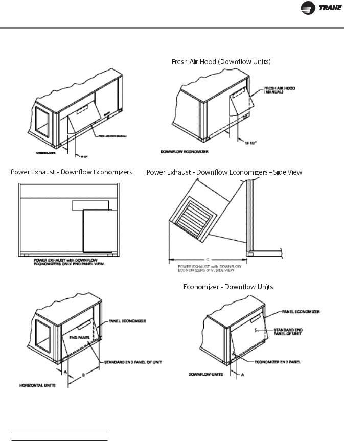
Figure 5. 150 - 300 Clearances
Fresh Air Hood (Horizontal Units)
Economizer - Horizontal Units
When applying economizer to horizontal units, connected ductwork must be run full size to allow proper operation of economizer damper.
Power Exhaust Dimensions
Unit Model # A B C
GERE150-240 19½ 64¾ 39
WSHP-SVX12B-EN |
15 |
Dimensions
Figure 6. 3 to 4-Ton Unit
16 |
WSHP-SVX12B-EN |
Dimensions
Figure 7. 5 -Ton Unit
WSHP-SVX12B-EN |
17 |

Dimensions
Figure 8. 6 -Ton Unit
18 |
WSHP-SVX12B-EN |
Loading...