


 Loading...
Installation, Operation,
and Maintenance
Gas Unit Heater
Indoor Gas-Fired Duct Furnace
 SAFETY WARNING
Only qualified personnel should install and service the equipment. The installation, starting up, and servicing of heating, ventilating, and air-conditioning equipment can be hazardous and requires specific knowledge and training. Improperly installed, adjusted or altered equipment by an unqualified person could result in death or serious injury. When working on the equipment, observe all precautions in the literature and on the tags, stickers, and labels that are attached to the equipment.
March 2012 |
GLND-SVX01B-EN |
Warnings, Cautions and Notices
Warnings, Cautions and Notices. Note that warnings, cautions and notices appear at appropriate intervals throughout this manual. Warnings are provide to alert installing contractors to potential hazards that could result in death or personal injury. Cautions are designed to alert personnel to hazardous situations that could result in personal injury, while notices indicate a situation that could result in equipment or property-damage-only accidents.
Your personal safety and the proper operation of this machine depend upon the strict observance of these precautions.
Read this manual thoroughly before operating or servicing this unit.
ATTENTION: Warnings, Cautions and Notices appear at appropriate sections throughout this literature. Read these carefully:
 WARNING
 CAUTIONs
NOTICE:
Indicates a potentially hazardous situation which, if not avoided, could result in death or serious injury.
Indicates a potentially hazardous situation which, if not avoided, could result in minor or moderate injury. It could also be used to alert against unsafe practices.
Indicates a situation that could result in equipment or property-damage only
Important
Environmental Concerns!
Scientific research has shown that certain man-made chemicals can affect the earth’s naturally occurring stratospheric ozone layer when released to the atmosphere. In particular, several of the identified chemicals that may affect the ozone layer are refrigerants that contain Chlorine, Fluorine and Carbon (CFCs) and those containing Hydrogen, Chlorine, Fluorine and Carbon (HCFCs). Not all refrigerants containing these compounds have the same potential impact to the environment. Trane advocates the responsible handling of all refrigerants-including industry replacements for CFCs such as HCFCs and HFCs.
Responsible Refrigerant Practices!
Trane believes that responsible refrigerant practices are important to the environment, our customers, and the air conditioning industry. All technicians who handle refrigerants must be certified. The Federal Clean Air Act (Section 608) sets forth the requirements for handling, reclaiming, recovering and recycling of certain refrigerants and the equipment that is used in these service procedures. In addition, some states or municipalities may have additional requirements that
must also be adhered to for responsible management of refrigerants. Know the applicable laws and follow them.
 WARNING
Proper Field Wiring and Grounding
Required!
All field wiring MUST be performed by qualified personnel. Improperly installed and grounded field wiring poses FIRE and ELECTROCUTION hazards. To avoid these hazards, you MUST follow requirements for field wiring installation and grounding as described in NEC and your local/state electrical codes. Failure to follow code could result in death or serious injury.
 WARNING
Personal Protective Equipment (PPE)
Required!
Installing/servicing this unit could result in exposure to electrical, mechanical and chemical hazards.
•Before installing/servicing this unit, technicians MUST put on all Personal Protective Equipment (PPE) recommended for the work being undertaken. ALWAYS refer to appropriate MSDS sheets and OSHA guidelines for proper PPE.
•When working with or around hazardous chemicals, ALWAYS refer to the appropriate MSDS sheets and OSHA guidelines for information on allowable personal exposure levels, proper respiratory protection and handling recommendations.
•If there is a risk of arc or flash, technicians MUST put on all Personal Protective Equipment (PPE) in accordance with NFPA 70E or other country-specific requirements for arc flash protection, PRIOR to servicing the unit.
Failure to follow recommendations could result in death or serious injury.
ATTENTION: READ THIS MANUAL AND ALL LABELS ATTACHED TO THE UNIT CAREFULLY BEFORE ATTEMPTING TO INSTALL, OPERATE OR SERVICE THESE UNITS! CHECK UNIT DATA PLATE FOR TYPE OF GAS AND ELECTRICAL SPECIFICATIONS AND MAKE CERTAIN THAT THESE AGREE WITH THOSE AT POINT OF INSTALLATION. RECORD THE UNIT MODEL AND SERIAL No.(s) IN THE SPACE PROVIDED. RETAIN FOR FUTURE REFERENCE.
© 2012 Trane All rights reserved |
GLND-SVX01B-EN |
Warnings, Cautions and Notices
 WARNING
Hazardous Service Procedures!
The maintenance and troubleshooting procedures recommended in this manual could result in exposure to electrical, mechanical or other potential safety hazards. Always refer to the safety warnings provided throughout this manual concerning these procedures. When possible, disconnect all electrical power including remote disconnect and discharge all energy storing devices such as capacitors before servicing. Follow proper lockout/tagout procedures to ensure the power can not be inadvertently energized. When necessary to work with live electrical components, have a qualified licensed electrician or other individual who has been trained in handling live electrical components perform these tasks. Failure to follow all of the recommended safety warnings provided, could result in death or serious injury.
 WARNING
Overheating or Flooding Could Cause Fire or Explosion!
Overheating or flooding (where any part of the duct furnace has been under water) could result in fire or explosion. Should overheating occur, or the gas supply fails to shut off, shut off the manual gas valve to the duct furnace before shutting off the electrical supply. Do not use the duct furnace if any part has been under water. Immediately call a qualified service technician to inspect the duct furnace and replace any gas control which has been underwater. Failure to follow these recommendations could result in death or serious injury.
 WARNING
Hazardous Gases and Flammable
Vapors!
Exposure to hazardous gases from fuel substances have been shown to cause cancer, birth defects or other reproductive harm. Improper installation, adjustment, alteration, service or use of this product could cause flammable mixtures. To avoid hazardous gases and flammable vapors follow proper installation and set up of this product and all warnings as provided in this manual. Failure to follow all instructions could result in death or serious injury.
Trademarks
Trane and the Trane logo are trademarks of Trane in the United States and other countries. All trademarks referenced in this document are the trademarks of their respective owners.
Dow Corning is a registered trademark of Dow Corning Corporation.
GLND-SVX01B-EN |
3 |
Introduction
 WARNING
Safety Alert!
You MUST follow all recommendations below. Failure to do so could result in death or serious injury.
For Your Safety
The use and storage of gasoline or other flammable vapors and liquids in open containers in the vicinity of this appliance is hazardous.
If you smell gas:
1.Open windows.
2.Do not touch electrical switches.
3.Extinguish any open flame.
4.Immediately call your gas supplier from a neighbor’s phone. Follow the gas supplier’s instructions.
Approved For Use in California When
Equipped With Spark Ignition
 WARNING
Toxic Hazard!
Install, operate and maintain unit in accordance with manufacturer’s instructions to avoid exposure to fuel substances or substances from incomplete combustion which could result in death or serious illness. The state of California has determined that these substances may cause cancer, birth defects, or other reproductive harm.
Installer’s Responsibility
Installer Please Note: This equipment has been test fired and inspected. It has been shipped free from defects from our factory. However, during shipment and installation, problems such as loose wires, leaks, or loose fasteners may occur. It is the installer’s responsibility to inspect and correct any problems that may be found.
Receiving Instructions
Inspect shipment immediately when received to determine if any damage has occurred to the unit during shipment. After the unit has been uncrated, check for any visible damage to the unit. If any damage is found, the consignee should sign the bill of lading indicating such damage and immediately file claim for damage with the transportation company.
Important: It is the equipment owner’s responsibility to provide any scaffolding or other apparatus required to perform emergency service or annual/periodic maintenance to this equipment.
4 |
GLND-SVX01B-EN |

Table of Contents
Warnings, Cautions and Notices . . . . . . . . . . |
2 |
Wiring Diagrams . . . . . . . . . . . . . . . . . . . . . . . . |
42 |
Model Number Descriptions . . . . . . . . . . . . . . |
6 |
|
|
Indoor Gas Heating Units . . . . . . . . . . . . . . . |
6 |
|
|
Horizontal Blower Assembly . . . . . . . . . . . . |
6 |
|
|
General Information . . . . . . . . . . . . . . . . . . . . . |
7 |
|
|
Description . . . . . . . . . . . . . . . . . . . . . . . . . . . |
7 |
|
|
General Safety Information . . . . . . . . . . . . . |
7 |
|
|
Identification of Parts . . . . . . . . . . . . . . . . . . |
8 |
|
|
Unit Dimensions and Weights . . . . . . . . . . . . |
9 |
|
|
Installation: Mechanical . . . . . . . . . . . . . . . . . |
11 |
|
|
Clearances . . . . . . . . . . . . . . . . . . . . . . . . . |
12 |
|
|
Air Flow . . . . . . . . . . . . . . . . . . . . . . . . . . . |
13 |
|
|
Combustion Inlet Air Ventilation . . . . . . . |
13 |
|
|
Suspension . . . . . . . . . . . . . . . . . . . . . . . . |
13 |
|
|
Nozzle Assembly . . . . . . . . . . . . . . . . . . . |
14 |
|
|
Installation: Piping . . . . . . . . . . . . . . . . . . . . . . |
16 |
|
|
Gas Piping . . . . . . . . . . . . . . . . . . . . . . . . . . . |
16 |
|
|
Pipe Sizing . . . . . . . . . . . . . . . . . . . . . . . . |
16 |
|
|
Pipe Installation . . . . . . . . . . . . . . . . . . . . . . |
17 |
|
|
Installation: Venting . . . . . . . . . . . . . . . . . . . |
18 |
|
|
Venting for Power Vented (Category III) Duct |
|
|
|
Furnaces . . . . . . . . . . . . . . . . . . . . . . . . . . |
19 |
|
|
Installation: Electrical . . . . . . . . . . . . . . . . . . . |
25 |
|
|
Electrical Connections . . . . . . . . . . . . . . . . . |
25 |
|
|
Thermostat Wiring and Location . . . . . . |
25 |
|
|
Start-Up . . . . . . . . . . . . . . . . . . . . . . . . . . . . . . . |
27 |
|
|
Operation . . . . . . . . . . . . . . . . . . . . . . . . . . . . |
27 |
|
|
Power Vented Duct Furnaces with Intermit- |
|
|
|
tent (Spark) Pilot Ignition . . . . . . . . . . . . . |
27 |
|
|
Gas Equipment Start-Up . . . . . . . . . . . . . . . |
32 |
|
|
Maintenance . . . . . . . . . . . . . . . . . . . . . . . . . . . |
33 |
|
|
Periodic Service . . . . . . . . . . . . . . . . . . . . |
33 |
|
|
Installation Instructions for Field Replace- |
|
|
|
ment of Power Venter Motor . . . . . . . . . . |
36 |
|
|
How to Order Replacement Parts . . . . . . |
37 |
|
|
Diagnostics . . . . . . . . . . . . . . . . . . . . . . . . . . . . |
38 |
|
|
Troubleshooting . . . . . . . . . . . . . . . . . . . . . . |
38 |
|
|
GLND-SVX01B-EN |
5 |
Model Number Descriptions
Indoor Gas Heating
Units
Note: All units are AGA approved. For CGA approved units, contact Air Handling Product Support.
Digit 1 — Gas Heating
Equipment
G = Gas Heating Equipment
Digit 2 — Product Type
L= High Efficiency Indoor Duct Furnace
Digit 3 — Fuel
N |
= |
Natural Gas |
P |
= |
LP Gas (Propane) |
Digit 4 — Development
Sequence
D = Fourth Generation
Digits 5, 6, 7 — Input Capacity
Single Furnace
003 |
= |
30 MBh |
015 |
= |
150 MBh |
004 |
= |
45 MBh |
017 |
= |
175 MBh |
006 |
= |
60 MBh |
020 |
= |
200 MBh |
007 |
= |
75 MBh |
022 |
= |
225 MBh |
009 |
= |
90 MBh |
025 |
= |
250 MBh |
010 |
= |
100 MBh |
030 |
= |
300 MBh |
012 = |
125 MBh |
035 |
= |
350 MBh |
|
|
|
|
040 |
= |
400 MBh |
Digit 8 — Main Power Supply
A |
= |
115/60/1 |
D |
= |
230/60/3 |
B |
= |
230/60/1 |
E |
= |
460/60/3 |
C |
= |
208/60/3 |
F |
= |
575/60/3 |
Digit 9 — Gas Control Option
D= Single-Stage, Intermittent Pilot Ignition
E= Two-Stage, Intermittent Pilot Ignition
H |
= |
Electronic Modulating with |
|
|
Room |
|
|
T-Stat, Intermittent Pilot Ignition |
J |
= |
Electronic Modulating with |
|
|
Duct-Stat, Intermittent Pilot |
|
|
Ignition |
L= Electronic Modulating with External 4–20 mA Input
N = Electronic Modulating with External 0–10 Vdc Input
T= Single Stage Direct Spark Ignition
V = Two-Stage, Direct Spark Ignition
Digit 10 — Design Sequence
G = Seventh Design
Digit 11 — Heat Exchanger
Material
1 |
= |
Aluminized Steel |
3 |
= |
#321 Stainless Steel |
Digit 12 — Rooftop
Arrangements
0 = None (Indoor Unit)
Digit 13 — Rooftop Heating Unit
Motor Selection
0= None (Indoor Unit and Rooftop Duct Furnace)
Digit 14 — Rooftop Fan Section
0= None (Indoor Unit and Rooftop Duct Furnace)
Digit 15 — Miscellaneous
Options
0 = None
A= #409 Stainless Steel Burners
B= Orifices For Elevation Above 2000 Feet (Specify Elevation)
C= #409 Stainless Steel Draft Diverter
D= Summer-Winter Switch
F= Horizontal Louvers
G= Horizontal and Vertical Louvers
K= Side Access Burner Drawer (Left Hand)1
L= Fan Time Delay Control
M= Side Access Burner Drawer (Right Hand)1
1The left or right hand side of the side access burner drawer, options K & M, is determined by facing the air outlet side of the duct furnace.
Horizontal Blower
Assembly
Digit 1, 2, 3 — Horizontal
Blower Assembly
Digit 4 — Development
Sequence
C = Third Generation
Digit 5, 6 — Blower Size
15 = Nominal 1500 cfm
20 = Nominal 2000 cfm
30 = Nominal 3000 cfm
45 = Nominal 4500 cfm
Digit 7 — Transition Size
(Specifies Duct Furnace Size)
0 |
= |
None |
|
|
|
A |
= |
100 MBh |
F |
= |
225 MBh |
B |
= |
125 MBh |
G |
= |
250 MBh |
C |
= |
150 MBh |
H |
= |
300 MBh |
D |
= |
175 MBh |
J |
= |
350 MBh |
E |
= |
200 MBh |
K |
= |
400 MBh |
Digit 8 — Main Power Supply
A |
= |
115/60/1 |
D |
= |
230/60/3 |
B |
= |
230/60/1 |
E |
= |
460/60/3 |
C |
= |
208/60/3 |
|
|
|
Digit 9 — Motor Horsepower
A |
= |
1/3 hp |
D |
= |
1 hp |
B |
= |
1/2 hp |
E |
= |
1-1/2 hp |
C |
= |
3/4 hp |
F |
= |
2 hp |
Digit 10 — Design Sequence
D = Fourth Design
Digit 11 — Miscellaneous
Options
0 |
= |
None |
1 |
= |
Insulation |
3 |
= |
Totally Enclosed Motor |
6 |
GLND-SVX01B-EN |
General Information
Description
The duct furnace design is certified by ETL for use with natural and LP (propane) gases. ANSI and NFPA Standards as well as Canadian installation codes referred to in this manual are the ones that were applicable at the time that the design was certified. In addition, the duct furnace may be installed on the downstream side of a cooling unit, without need of a bypass duct.
If the unit is to be installed at an altitude exceeding 2,000 feet (610 m) above sea level, derate the input by
4 percent for each 1,000 foot (305 m) rise above sea level. Special orifices are required for installations above 2,000 feet (610 m).
When units are installed in Canada, any reference to derations at altitudes in excess of 2000 feet (610 m) are to be ignored. At altitudes of 2000 to 4500 feet (610 to 1372 m), the units must be orificed to 90 percent of the normal altitude rating, and be so marked in accordance with the ETL certification.
General Safety Information
Important: This product must be installed by a licensed plumber or gas fitter when installed within the Commonwealth of Massachusetts.
 WARNING
Safety Alert!
You MUST follow all recommendations below. Failure to do so could result in death or serious injury.
•Installation must be made in accordance with local codes, or in absence of local codes with the latest edition of ANSI Standard Z223.1 (N.F.P.A. No. 54) National Fuel Gas Code.
All of the ANSI and NFPA Standards referred to in these installation instructions are those that were applicable at the time the design of this appliance was certified. The ANSI Standards are available from the CSA Information Services, 1-800-463-6727. The NFPA Standards are available from the National Fire Protection Association, Batterymarch Park, Quincy, MA 02269. These duct furnaces are designed for use in airplane hangars when installed in accordance with current ANSI/NFPA No. 409 and in public garages when installed in accordance with current NFPA No. 88A and NFPA No. 88B.
If installed in Canada, the installation must conform with local building codes, or in absence of local building codes, with CSA-B149.1 “Installation Codes for Natural Gas Burning Appliances and Equipment” or CSA-B149.2
“Installation Codes for Propane Gas Burning Appliances and Equipment”. These indoor duct furnaces have been designed and certified to comply with CSA 2.6. Also see sections on installation in “Aircraft Hangers,” p. 11 and “Public Garages,” p. 11.
•Do not alter the duct furnace in any way or damage to the unit and/or severe personal injury or death could occur!
•Turn off the gas supply and disconnect all electric power, including remote disconnects before servicing unit. Follow proper lockout/ tagout procedures to ensure the power can not be inadvertently energized and the gas can not be inadvertently turned on. Failure to turn off gas or disconnect power before servicing could result in death or serious injury.
•Follow installation instructions CAREFULLY to avoid creating unsafe conditions. All wiring should be done and checked by a qualified electrician, using copper wire only. All external wiring must conform to applicable local codes and to the latest edition of the National Electrical Code ANSI/NFPA No. 70.
•All gas connections should be made and leaktested by a suitably qualified individual, per instructions in this manual. Also follow procedures listed in “Gas Equipment Start-Up,” p. 32.
•Use only the fuel for which the duct furnace is designed (see rating plate). Using LP gas in a heater that requires natural gas, or vice versa, will create the risk of gas leaks, carbon monoxide poisoning and explosion.
Important: Do not attempt to convert the furnace for use with a fuel other than the one intended. Such conversion is dangerous, as it could create the risks listed previously.
•Make certain that the power source conforms to the electrical requirements of the furnace.
•All field-installed wiring must be completed by qualified personnel. All field-installed wiring must comply with NEC and applicable local codes. Failure to follow this instruction could result in death or serious injuries.
•Special attention must be given to any grounding information pertaining to this duct furnace. To prevent the risk of electrocution, the furnace must be securely and adequately grounded. This should be accomplished by connecting a grounded conductor between the service panel and the furnace. To ensure a proper
GLND-SVX01B-EN |
7 |
General Information
ground, the grounding means must be tested by a qualified electrician.
•Do not insert fingers or foreign objects into the furnace or its air moving device. Do not block or tamper with the heater in any manner while in operation or just after it has been turned off, as some parts may be hot enough to cause injury.
•This furnace is intended for general heating applications ONLY. It must NOT be used in potentially dangerous locations such as flammable, explosive, chemical-laden or wet atmospheres.
•In cases in which property damage may result from malfunction of the furnace, a backup system or a temperature sensitive alarm should be used.
•When connecting to existing gas lines be sure to valve off the gas supply ahead of connection point. To avoid explosion or possible fire, always purge all residual gas from piping before cutting into existing line or removing threaded fittings. Failure to remove all gas vapors could result in death or serious injury or equipment or property- only-damage.
Unless otherwise specified, the following conversions may be used for calculating SI unit measurements:
1 foot = 0.305 m |
1 inch water column = 0.249 kPa |
1 inch = 25.4 mm |
1 meter/second = FPM ÷ 196.8 |
1 psig = 6.894 kPa |
1 liter/second = CFM x 0.472 |
1 pound = 0.453 kg |
1000 Btu per hour = 0.293 kW |
1 gallon = 3.785 L |
1000 Btu/Cu. Ft. = 37.5 MJ/m3 |
|
1 cubic foot = 0.028 m3 |
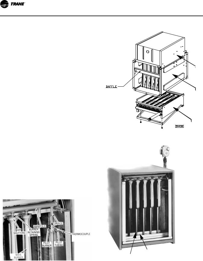
Identification of Parts
Figure 1. Burner assembly parts (bottom view)
OR ELECTRODE/SENSING
LEAD LOCATION
Figure 2. Duct furnace components
1 |
2 |
3 |
Figure 3. Burners/Controls (bottom view)
 1
1
 2
2
 3
3
 4
4
5
6
1. |
“Packaged” Gas Valve |
4. |
Burner “Drawer” |
2. |
Pilot Observation Point |
5. |
Flame Carryover |
3. |
Pilot Burner Assembly Parts |
6. |
Main Burner |
8 |
GLND-SVX01B-EN |

Unit Dimensions and Weights
Figure 4. Power Vented Furnace—bottom service access
Table 1. |
Power Vented Duct Furnace |
|
|
|
|
|||
|
|
|
|
|
|
Gas Inlet |
|
|
|
A |
B |
C |
D (Dia.) |
F |
|
in. |
Weight |
Unit Size |
in. (mm) |
in. (mm) |
in. (mm) |
in. (mm) |
in. (mm) |
Nat. |
LP |
lb (kg) |
100 |
17-7/8 |
15-1/2 |
17-1/8 |
4 |
23-7/8 |
1/2 |
1/2 |
173 |
|
(454) |
(394) |
(435) |
(102) |
(606) |
|
|
(78) |
125 |
20-5/8 |
18-1/4 |
19-7/8 |
4 |
25-5/8 |
1/2 |
1/2 |
186 |
|
(524) |
(464) |
(505) |
(102) |
(651) |
|
|
(84) |
150 |
20-5/8 |
18-1/4 |
19-7/8 |
4 |
26-5/8 |
1/2 |
1/2 |
197 |
|
(524) |
(464) |
(505) |
(102) |
(676) |
|
|
(89) |
175 |
23-3/8 |
21 |
22-5/8 |
4 |
29-3/8 |
1/2 |
1/2 |
216 |
|
(594) |
(533) |
(575) |
(102) |
(746) |
|
|
(98) |
200 |
26-1/8 |
23-3/4 |
25-3/8 |
5 |
32-1/8 |
1/2 |
1/2 |
232 |
|
(664) |
(603) |
(645) |
(127) |
(816) |
|
|
(105) |
225 |
28-7/8 |
26-1/2 |
28-1/8 |
5 |
34-7/8 |
3/4 |
1/2 or 3/4 |
254 |
|
(733) |
(673) |
(714) |
(127) |
(886) |
|
|
(115) |
250 |
31-5/8 |
29-1/4 |
30-7/8 |
5 |
37-5/8 |
3/4 |
1/2 or 3/4 |
263 |
|
(803) |
(743) |
(784) |
(127) |
(956) |
|
|
(119) |
300 |
37-1/8 |
34-3/4 |
36-3/8 |
6 |
43-1/8 |
3/4 |
1/2 or 3/4 |
312 |
|
(943) |
(883) |
(924) |
(152) |
(1095) |
|
|
(142) |
350 |
42-5/8 |
40-1/4 |
41-7/8 |
6 |
48-5/8 |
3/4 |
1/2 or 3/4 |
389 |
|
(1083) |
(1022) |
(1064) |
(152) |
(1235) |
|
|
(176) |
400 |
48-1/8 |
45-3/4 |
47-3/8 |
6 |
54-1/8 |
3/4 |
1/2 or 3/4 |
403 |
|
(1222) |
(1162) |
(1203) |
(152) |
(1375) |
|
|
(183) |
Figure 5. Power Vented Duct Furnace—side service access
GLND-SVX01B-EN |
9 |
Unit Dimensions and Weights
Table 2. |
Performance data |
|
|
|
|
|
|
|
|
|
|
|
|
|
|
|
|
|
|
|
Input |
|
|
|
|
|
|
|
|
|
MAX |
MIN |
Output |
MIN |
Temp. Rise |
P.D. |
MAX |
Temp. Rise |
P.D. |
Unit Size |
MBh (kW) |
MBh (kW) |
MBh (kW) |
cfm (m3/s) |
°F (°C) |
in. of H2O (kPa) |
cfm (m3/s) |
°F (°C) |
in. of H2O (kPa) |
100 |
100 |
50 |
80 |
929 |
80 |
0.12 |
2469 |
30 |
0.90 |
|
(29.3) |
(14.6) |
(23.4) |
(0.438) |
(44) |
(0.03) |
(1.165) |
(17) |
(0.22) |
|
|
|
|
|
|
|
|
|
|
125 |
125 |
62.5 |
100 |
1157 |
80 |
0.13 |
3086 |
30 |
0.80 |
|
(36.6) |
(18.3) |
(29.3) |
(0.546) |
(44) |
(0.03) |
(1.457) |
(17) |
(0.20) |
|
|
|
|
|
|
|
|
|
|
150 |
150 |
75 |
120 |
1389 |
80 |
0.15 |
3704 |
30 |
0.75 |
|
(43.9) |
(22.0) |
(35.1) |
(0.656) |
(44) |
(0.04) |
(1.748) |
(17) |
(0.19) |
|
|
|
|
|
|
|
|
|
|
175 |
175 |
87.5 |
140 |
1620 |
80 |
0.14 |
4321 |
30 |
0.75 |
|
(51.2) |
(25.6) |
(41.0) |
(0.765) |
(44) |
(0.03) |
(2.040) |
(17) |
(0.19) |
|
|
|
|
|
|
|
|
|
|
200 |
200 |
100 |
160 |
1852 |
80 |
0.14 |
4938 |
30 |
0.75 |
|
(58.6) |
(29.3) |
(46.9) |
(0.874) |
(44) |
(0.03) |
(2.331) |
(17) |
(0.19) |
|
|
|
|
|
|
|
|
|
|
225 |
225 |
112.5 |
180 |
2083 |
80 |
0.14 |
5556 |
30 |
0.75 |
|
(65.9) |
(32.9) |
(52.7) |
(0.983) |
(44) |
(0.03) |
(2.622) |
(17) |
(0.19) |
|
|
|
|
|
|
|
|
|
|
250 |
250 |
125 |
200 |
2315 |
80 |
0.14 |
6173 |
30 |
0.80 |
|
(73.2) |
(36.6) |
(58.6) |
(1.093) |
(44) |
(0.03) |
(2.914) |
(17) |
(0.20) |
|
|
|
|
|
|
|
|
|
|
300 |
300 |
150 |
240 |
2778 |
80 |
0.13 |
7407 |
30 |
0.90 |
|
(87.8) |
(43.9) |
(70.3) |
(1.311) |
(44) |
(0.03) |
(3.496) |
(17) |
(0.22) |
|
|
|
|
|
|
|
|
|
|
350 |
350 |
175 |
280 |
3241 |
80 |
0.13 |
8642 |
30 |
0.90 |
|
(102.5) |
(51.2) |
(82.0) |
(1.530) |
(44) |
(0.03) |
(4.079) |
(17) |
(0.22) |
|
|
|
|
|
|
|
|
|
|
400 |
400 |
200 |
320 |
3704 |
80 |
0.14 |
9877 |
30 |
0.90 |
|
(117.1) |
(58.6) |
(93.7) |
(1.748) |
(44) |
(0.03) |
(4.662) |
(17) |
(0.22) |
|
|
|
|
|
|
|
|
|
|
Notes:
1.Ratings are shown for unit installations at elevations between 0 and 2,000 ft. (610 m).
2.For unit installations in U.S.A. above 2,000 ft. (610 m), the unit input must be derated 4 percent for each 1,000 ft. (305 m) above sea level; refer to local codes, or in absence of local codes, refer to the latest edition of the National Fuel Gas Code, ANSI Standard Z223.1 (N.F.P.A. No. 54).
3.For installations in Canada, any references to deration at altitudes in excess of 2,000 ft. (610 m) are to be ignored.
4.At altitudes of 2,000 to 4,500 ft. (610 to 1372 m), the unit must be derated 90 percent of the normal altitude rating, and be so marked in accordance with the ETL certification.
Figure 6. Temperature rise and pressure drop graph
10 |
GLND-SVX01B-EN |
Installation: Mechanical
NOTICE:
Equipment Damage!
Do not install duct furnaces in corrosive or flammable atmospheres! Premature failure of, or severe damage to the unit could result! Avoid locations where extreme drafts can affect burner operation. Duct furnaces must not be installed in locations where air for combustion would contain chlorinated, halogenated or acidic vapors. If located in such an environment, premature failure of the unit could occur!
When the unit is equipped with an automatic gas ignition system, the duct furnaces must be installed such that the gas ignition control system is not directly exposed to water spray, rain, or dripping water.
Note: Location of duct furnaces is related directly to the selection of sizes. Basic rules are as follows:
Aircraft Hangers. Duct furnaces must be installed in aircraft hangars and public garages as follows: in aircraft hangars, duct furnaces must be at least 10 feet (3.0 m) above the upper surface of wings or engine enclosures of the highest aircraft to be stored in the hangar, and 8 feet (2.4 m) above the floor in shops, offices and other sections of the hangar where aircraft are not stored or housed. Refer to current ANSI/NFPA No. 409, Aircraft Hangars. In Canada, installation is suitable in aircraft hangars when acceptable to the enforcing authorities.
Public Garages. In repair garages, duct furnaces must be installed in a detached building or room separate from repair areas as specified in the latest edition of NFPA 88B, Repair Garages.
In parking structures, duct furnaces must be installed so that the burner flames are located a minimum of 18 inches (457 mm) above the floor or protected by a partition not less than 18 inches (457 mm) high. Refer to the latest edition of NFPA 88A, Parking Structures.
In Canada, installation must be in accordance with the latest edition of CSA B149 “Installation Codes for Gas Burning Appliances and Equipment.”
NOTICE:
Maintain Minimum Thermostat Setting!
Duct furnaces should not be installed to maintain low temperatures and/or freeze protection of buildings. A minimum of 50°F (10°C) thermostat setting must be maintained. If duct furnaces are operated to maintain lower than 50°F (10°C), hot flue gases are cooled inside the heat exchanger to a point where water vapor (a flue gas by-product) condenses onto the heat exchanger walls. The result is a mildly corrosive acid that prematurely corrodes the aluminized heat exchanger and can actually drip water down from the duct furnace onto the floor surface. Additional duct furnaces should be installed if a minimum 50°F (10°C) thermostat setting cannot be maintained. Failure to follow these recommendations could result in equipment or property damage.
 WARNING
Overheating or Flooding Could Cause Fire or Explosion!
Overheating or flooding (where any part of the duct furnace has been under water) could result in fire or explosion. Should overheating occur, or the gas supply fails to shut off, shut off the manual gas valve to the duct furnace before shutting off the electrical supply. Do not use the duct furnace if any part has been under water. Immediately call a qualified service technician to inspect the duct furnace and replace any gas control which has been underwater. Failure to follow these recommendations could result in death or serious injury.
 WARNING
Hazardous Gases and Flammable Vapors!
Exposure to hazardous gases from fuel substances have been shown to cause cancer, birth defects or other reproductive harm. Improper installation, adjustment, alteration, service or use of this product could cause flammable mixtures. To avoid hazardous gases and flammable vapors follow proper installation and set up of this product and all warnings as provided in this manual. Failure to follow all instructions could result in death or serious injury.
GLND-SVX01B-EN |
11 |
Installation: Mechanical
Clearances
 WARNING
Combustible Materials!
Maintain proper clearance between the unit heat exchanger, vent surfaces, and combustible materials. Refer to unit nameplate and installation instructions for proper clearances. Improper clearances could result in a fire hazard. Failure to maintain proper clearances could result in death or serious injury or property damage.
Maintain adequate clearances around air openings into combustion chamber:
Table 3. |
Minimum clearances |
|
|
Sides |
6” (152 mm) |
|
|
Top |
6” (152 mm) |
|
|
Bottom |
6” (152 mm) |
|
|
Flue |
6” (152 mm) |
Note: When the clearances required for accessibility are greater than the minimum required safety clearances, the accessibility clearances take precedence.
Accessibility
If the unit is a bottom service access type, allow a minimum of 21 inches (533 mm) at the bottom of the unit to facilitate servicing the burners and pilot, or six inches (152 mm) if the unit has a side access burner drawer. Provision should also be made to assure accessibility for recurrent maintenance purposes.
Drafts
Avoid installing the duct furnace in an extremely drafty location. Strong drafts may cause pilot outage. Units with intermittent pilot ignition may be preferable in areas where drafts cannot be avoided.
Atmospheres containing commercial solvents or chlorinated hydrocarbons will produce corrosive acids when coming in contact with the flames. This will greatly reduce the life of the gas duct furnace and may void the warranty. Avoid such areas.
 WARNING
Fire Hazard!
Ductwork
Properly designed and installed ductwork, providing a uniformly distributed flow of air across the surfaces of the heat exchanger, is essential to satisfactory unit performance and life of the equipment.
All duct connection flanges/seams must be sealed to prevent air leaks. Sealant/tape must be suitable for temperatures 250°F (121°C) minimum.
NOTICE:
Use 90° Duct Connection Flanges!
Ducts must be properly connected to duct furnaces for operation. Do not straighten the 90° duct connection flanges on the duct furnaces. Straightening the 90° duct connection flanges will affect the operation of the furnace and will void the warranty.
If uniform air distribution is not obtained, install additional baffles and/or turning vanes in the ductwork.
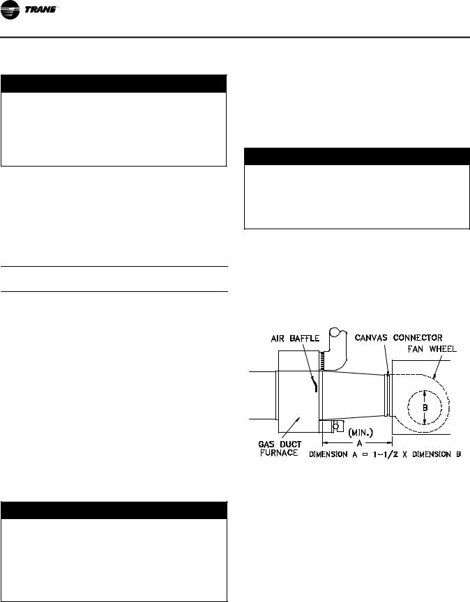
Figure 7 and Figure 8 illustrate recommended ductwork designs for both the straight-through and elbowed air inlet arrangements.
Figure 7. Recommended design for field installation of ductwork for straight-through arrangement
If the gas duct furnace is to be used in a building classified as having a hazardous atmosphere, the installation must comply with the standards set by the National Board of Fire Underwriters. Consult the authorities having jurisdiction before starting the job. Failure to follow recommendations could result in death or serious injury.
The duct furnace must be installed on the positive pressure side of the air circulation blower.
12 |
GLND-SVX01B-EN |
Installation: Mechanical
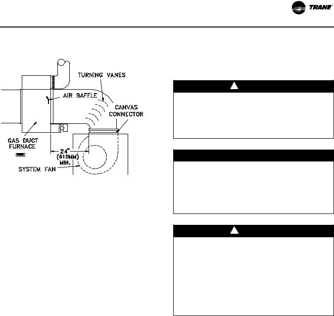
Figure 8. Recommended ductwork design for elbowed arrangement
Access panels large enough to observe smoke and reflected light, and to detect the presence of leaks in the heating equipment, are required both upstream and downstream from gas duct furnaces. These panels must be sealed to prevent air leaks. If allowed by local regulations, install canvas connectors between the ductwork and fan discharge opening to eliminate the transmission of mechanical vibration.
Air Flow
The installation is to be adjusted to obtain an air throughput within the range specified on the appliance rating plate.
Combustion Inlet Air Ventilation
Inlet Air From Another Room
If the duct furnace is installed in a tightly constructed room or compartment, provide two inlet air openings. The size of each vent opening should be no less than one square inch (6.452 square centimeters) of free area for each 1000 Btu/hr. (293 W) input. Each opening must not be less than 100 square inches (645 square centimeters).
Inlet Air From Outdoors
If the enclosed space is to have inlet combustion air from the outside, the vent opening must not be smaller than one square inch (6.452 square centimeters) of free area for each 2500–3000 Btu/hr (733–879 W) input. Each opening must not be less than 100 square inches (645 square centimeters).
Bypass
When a gas duct furnace is installed to operate in conjunction with a summer air conditioning system, the cfm air delivery of the system blower should be adjusted to meet the design air volume requirements for cooling. If this cfm delivery is greater than that required for heating,
resulting in a low air temperature rise, install a damper bypass around the gas duct furnace to bypass a portion of the air.
Suspension
 WARNING
Heavy Objects!
Ensure that all hardware used in the suspension of each duct furnace is capable of supporting the unit weight. Failure to do so could result in unit falling off its mounting location, which could result in death or serious injury.
NOTICE:
Equipment Damage!
The duct furnace must be hung level from side to side and front to back, from four suspension points provided at the top of the unit. Failure to do so could result in poor performance and/or premature failure of the unit. Refer to Figure 9, p. 14 for typical suspension arrangements.
 WARNING
Heavy Objects!
Make certain that the lifting methods used to lift the duct furnace and the method of suspension used in the field installation of the duct furnace are capable of uniformly supporting the weight of the furnace at all times. Make certain that the structure to which the furnace is mounted is capable of supporting its weight. Under no circumstances must the heater gas lines, the venting system or the electrical conduit be used for support. Failure to follow recommendations could result in death, serious injury, or property damage.
GLND-SVX01B-EN |
13 |
Loading...