


 Loading...
Trane CCRC020, CCRC025, CCRC030, CCRC035, CCRC040 Installation and Maintenance Manual
...Installation, Operation,
and Maintenance
Air Cooled Condenser
20-60Ton
Models |
|
|
CCRC020 |
CCRC025 |
CCRC030 |
CCRC035 |
CCRC040 |
CCRC050 |
CCRC060 |
|
|
CIRC020 |
CIRC025 |
CIRC030 |
CIRC035 |
CIRC040 |
CIRC050 |
CIRC060 |
|
|
 SAFETY WARNING
Only qualified personnel should install and service the equipment. The installation, starting up, and servicing of heating, ventilating, and air-conditioning equipment can be hazardous and requires specific knowledge and training. Improperly installed, adjusted or altered equipment by an unqualified person could result in death or serious injury. When working on the equipment, observe all precautions in the literature and on the tags, stickers, and labels that are attached to the equipment.
February 2013 |
CXRC-SVX01F-EN |
Warnings, Cautions and Notices
Warnings, Cautions and Notices. Note that warnings, cautions and notices appear at appropriate intervals throughout this manual. Warnings are provide to alert installing contractors to potential hazards that could result in death or personal injury. Cautions are designed to alert personnel to hazardous situations that could result in personal injury, while notices indicate a situation that could result in equipment or property-damage-only accidents.
Your personal safety and the proper operation of this machine depend upon the strict observance of these precautions.
Read this manual thoroughly before operating or servicing this unit.
must also be adhered to for responsible management of refrigerants. Know the applicable laws and follow them.
 WARNING
Proper Field Wiring and Grounding
Required!
All field wiring MUST be performed by qualified personnel. Improperly installed and grounded field wiring poses FIRE and ELECTROCUTION hazards. To avoid these hazards, you MUST follow requirements for field wiring installation and grounding as described in NEC and your local/state electrical codes. Failure to follow code could result in death or serious injury.
ATTENTION: Warnings, Cautions and Notices appear at appropriate sections throughout this literature. Read these carefully:
 WARNING
 CAUTIONs
NOTICE:
Indicates a potentially hazardous situation which, if not avoided, could result in death or serious injury.
Indicates a potentially hazardous situation which, if not avoided, could result in minor or moderate injury. It could also be used to alert against unsafe practices.
Indicates a situation that could result in equipment or property-damage only
Important
Environmental Concerns!
Scientific research has shown that certain man-made chemicals can affect the earth’s naturally occurring stratospheric ozone layer when released to the atmosphere. In particular, several of the identified chemicals that may affect the ozone layer are refrigerants that contain Chlorine, Fluorine and Carbon (CFCs) and those containing Hydrogen, Chlorine, Fluorine and Carbon (HCFCs). Not all refrigerants containing these compounds have the same potential impact to the environment.Trane advocates the responsible handling of all refrigerants-including industry replacements for CFCs such as HCFCs and HFCs.
Responsible Refrigerant Practices!
Trane believes that responsible refrigerant practices are important to the environment, our customers, and the air conditioning industry. All technicians who handle refrigerants must be certified.The Federal Clean Air Act (Section 608) sets forth the requirements for handling, reclaiming, recovering and recycling of certain refrigerants and the equipment that is used in these service procedures. In addition, some states or municipalities may have additional requirements that
 WARNING
Hazardous Voltage w/Capacitors!
Disconnect all electric power, including remote disconnects and discharge all motor start/run capacitors before servicing. Follow proper lockout/ tagout procedures to ensure the power cannot be inadvertently energized. For variable frequency drives or other energy storing components provided by Trane or others, refer to the appropriate manufacturer’s literature for allowable waiting periods for discharge of capacitors. Verify with an appropriate voltmeter that all capacitors have discharged. Failure to disconnect power and discharge capacitors before servicing could result in death or serious injury.
For additional information regarding the safe discharge of capacitors, see PROD-SVB06A-EN
 WARNING
Personal Protective Equipment (PPE)
Required!
Installing/servicing this unit could result in exposure to electrical, mechanical and chemical hazards.
•Before installing/servicing this unit, technicians MUST put on all Personal Protective Equipment (PPE) recommended for the work being undertaken. ALWAYS refer to appropriate MSDS sheets and OSHA guidelines for proper PPE.
•When working with or around hazardous chemicals, ALWAYS refer to the appropriate MSDS sheets and OSHA guidelines for information on allowable personal exposure levels, proper respiratory protection and handling recommendations.
•If there is a risk of arc or flash, technicians MUST put on all Personal Protective Equipment (PPE) in accordance with NFPA 70E or other country-specific requirements for arc flash protection, PRIOR to servicing the unit.
Failure to follow recommendations could result in death or serious injury.
© 2013Trane All rights reserved |
CXRC-SVX01F-EN |
Warnings, Cautions and Notices
NOTICE:
Use Copper Conductors Only!
Unit terminals are not designed to accept other types of conductors. Failure to use copper conductors could result in equipment damage.
Introduction
About This Manual
Note: One copy of this document ships inside the control panel of each unit and is customer property. It must be retained by the unit's maintenance personnel.
This booklet describes proper installation, operation, and maintenance procedures for air cooled systems. By carefully reviewing the information within this manual and following the instructions, risk of improper operation and/or component damage will be minimized. It is important that periodic maintenance be performed to help assure trouble free operation. A maintenance schedule is provided at the end of this manual. Should equipment failure occur, contact a qualified service organization with qualified, experienced HVAC technicians to properly diagnose and repair this equipment.
R-410A Refrigerant
•System is designed to be compatible with R-410A refrigerant.
Refer to previous IOM versions for R-407C and R-22 units, or contact your localTrane representative.
Refer to the appropriate IOM for air-cooled condenser CXRC-SVX01 and programming Intellipak controls PKGSVP01.
Air Cooled Condenser units are applied with SCRF/SIRF or SCRG/SIRG Commercial Self Contained units with IntelliPak controls or thermostat interface.
Cross References to related publications/ information
•IntelliPak® Self-Contained Programming Guide, PKG- SVP01*-EN
•Commercial Self-Contained IntelliPak Signature Series Installation, Owner, and Diagnostic Manual, SCXF- SVX01*-EN
•Commercial Self-Contained IntelliPak Modular Series Installation, Owner, and Diagnostic Manual, SCXG- SVX01*-EN
•TheTrane Reciprocating Refrigeration Manual
Revision Summary
CXRC-SVX01F-EN (13 Feb 2013)
Remove wiring diagrams. Add wiring diagram numbers and reference to e-library. Update operating principals to remove obsolete reference designators.
CXRC-SVX01E-EN (23 Oct 2012)
Updated fan motor information.
Trademarks
Trane, Intellipak,Trane 3-D and theTrane logo are trademarks ofTrane in the United States and other countries. All trademarks referenced in this document are the trademarks of their respective owners.
CXRC-SVX01F-EN |
3 |

Table of Contents |
|
Model Number Descriptions . . . . . . . . . . . |
. . . 5 |
General Data . . . . . . . . . . . . . . . . . . . . . . . . . |
. . . 6 |
Unit Description . . . . . . . . . . . . . . . . . . |
. . . 6 |
Pre-Installation . . . . . . . . . . . . . . . . . . . . . . . |
. . . 8 |
Receiving . . . . . . . . . . . . . . . . . . . . . . . . . . |
. . . 8 |
Contractor Installation Responsibilities |
. . . 8 |
Dimensions and Weights . . . . . . . . . . . . . . |
. . . 9 |
Service Clearances . . . . . . . . . . . . . . . . |
. . 10 |
Installation - Mechanical . . . . . . . . . . . . . . |
. . 13 |
Unit Handling Procedure . . . . . . . . . . . . |
. . 13 |
Installation Preparation . . . . . . . . . . . . . . |
. . 14 |
Unit Isolation . . . . . . . . . . . . . . . . . . . . . . |
. . 14 |
Leveling the Unit . . . . . . . . . . . . . . . . . |
. . 15 |
Refrigerant Piping . . . . . . . . . . . . . . . . . . |
. . 15 |
General Refrigerant Recommendations . 15 |
|
Interconnecting Piping . . . . . . . . . . . . . |
. . 16 |
Installation - Electrical . . . . . . . . . . . . . . . . . |
. . 17 |
General Electrical Recommendations . |
. . 17 |
Power Supply Wiring . . . . . . . . . . . . . . |
. . 17 |
Operating Principals . . . . . . . . . . . . . . . . . . |
. . 19 |
Control Sequences of Operation for Units |
|
with IntelliPak™ . . . . . . . . . . . . . . . . . . |
. . 19 |
Pre-Start Checklist . . . . . . . . . . . . . . . . . . . . |
. . 20 |
Start-Up and Shutdown . . . . . . . . . . . . . . . |
. . 21 |
Start-Up . . . . . . . . . . . . . . . . . . . . . . . . . . . |
. . 21 |
Normal Unit Shut Down . . . . . . . . . . . . . |
. . 21 |
Seasonal Shut Down . . . . . . . . . . . . . . . . |
. . 21 |
Seasonal Startup . . . . . . . . . . . . . . . . . . . |
. . 21 |
Maintenance . . . . . . . . . . . . . . . . . . . . . . . . . |
. . 22 |
Refrigerant System . . . . . . . . . . . . . . . . . |
. . 22 |
Refrigerant Leak Test Procedure . . . . . |
. . 22 |
System Evacuation Procedures . . . . . . |
. . 23 |
Refrigerant Charging . . . . . . . . . . . . . . |
. . 24 |
Maintenance Periodic Procedures . . . . . |
. . 25 |
Cleaning the Coil . . . . . . . . . . . . . . . . . |
. . 25 |
Low Ambient Damper Adjustment . . . |
. . 26 |
Troubleshooting . . . . . . . . . . . . . . . . . . . . |
. . 26 |
Wiring Diagrams . . . . . . . . . . . . . . . . . . . . . |
. . 27 |
4 |
CXRC-SVX01F-EN |

Model Number Descriptions
Digit 1 - Unit Model
C = Condenser
Digit 2 - Unit Type
C = Commercial
I = Industrial
Digit 3 - Condenser Medium
R = Remote
Digit 4 - Development Sequence
C = C
Digit 5, 6, 7 - Nominal Capacity
020 = 20Tons
029 = 29Tons
032 = 32Tons
035 = 35Tons
040 = 40Tons
050 = 50Tons
060 = 60Tons
Digit 8 - Unit Voltage
4 = 460 Volt/60 Hz/3 ph
5 = 575 Volt/60 Hz/3 ph
6 = 200 Volt/60 Hz/3 ph
Digit 9 -Control Option
0 = No Low Ambient, I-Pak
A= No Low Ambient,T-Stat
B = Low Ambient, I-Pak
C = Low Ambient,T-Stat
Digit 10, 11 - Design Sequence
** = Factory Assigned
Digit 12 - Unit Finish
1 = Paint - Slate Gray
2 = Protective Coating
3 = Protective Coating with Finish Coat
Digit 13 - Coil Options
A = Non-Coated Aluminum
C = Protective Coating Aluminum
Digit 14 - Unit Isolators
0 = None
A = Spring Isolators
B = Isopads
Digit 15 - Panels
0 = None
1 = Louvered Panels
Digit 16 - Agency
0 = None
T = With UL Listing
CXRC-SVX01F-EN |
5 |
General Data
Unit Description
Model CCRC/CIRC units function as the outdoor condenser unit for appropriately sized split refrigeration systems. These units operate in conjunction with a matched indoor compressor/evaporator configuration (Trane models SCRF, SIRF, SCRG, or SIRG) and provide refrigerant condensing for these systems down to a normal ambient temperature of 45°F. Operation to 0°F ambient is possible with the addition of the optional external mount low ambient dampers. Refer to the “Low Ambient Damper” section in this manual.
Model CCRC/CIRC remote air cooled condensers are dehydrated, leak tested, and charged with a holding charge of dry nitrogen. Units are tested for proper control operation before shipment.
The factory provided unit-mounted control panel contains all required fan cycling controls, compressor interlocks
and 115 V control power transformer. Each unit features two independent refrigerant circuits with an integral subcooling loop.The slab condenser coils are aluminum fins bonded to copper tubing. Louvered condenser grills are for coil protection and are an orderable option. Direct drive, vertical discharge fans are provided with built-in current and overload protection. Head pressure control dampers are available if low ambient operation is required.
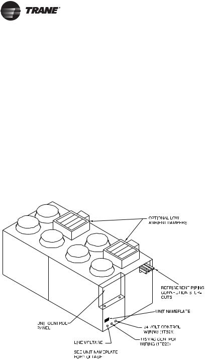
A bag containing the installation/ operation/maintenance manual, schematics, and other pertaining literature is provided and located in the control panel. Read all literature pertaining to unit before installation and operation. Figure 1 illustrates CCRC/CIRC exterior component locations
Figure 1. Model CCRC/CIRC typical unit components. 60-ton unit is shown


 8TB22
8TB22
Unit Nameplate
The nameplate on these units provide valuable identification information for the unit and its components. Provide all pertinent nameplate data when ordering parts or literature and when making other inquires.
The unit nameplate for 20 – 60 ton CCRC/CIRC units is mounted on the unit below the control box. See Figure 1. This nameplate specifies unit power requirements and also identifies the order number for the operation and maintenance literature of the unit.The owner should refer to this manual for information regarding the proper equipment operation and maintenance.
6 |
CXRC-SVX01F-EN |
General Data
Table 1. SCRF/SIRF Air–cooled self–contained and CCRC/CIRC remote air-cooled condenser, refrigerant data
SCRF/SIRF & CCRC/CIRC |
|
|
|
|
|
|
|
|
Unit Size |
20/20 |
25/29 |
29/29 |
30/35 |
35/35 |
40/40 |
50/50 |
60/60 |
|
|
|
|
|
|
|
|
|
No. of Refrigerant Circuits |
2 |
2 |
2 |
2 |
2 |
2 |
2 |
2 |
|
|
|
|
|
|
|
|
|
Operating Charge - lbs. R-410A |
35.5/35.5 |
44.5/33.5 |
51/37.5 |
71/35.5 |
75/37.5 |
86.5/39.5 |
98/50 |
101.5/101.5 |
Operating Charge - kg R-410A |
16.1/16.1 |
20.2/15.2 |
23.1/17 |
32.2/16.1 |
34/17 |
39.2/17.9 |
44.5/22.7 |
46/46 |
|
|
|
|
|
|
|
|
|
Cond. Storage Cap. - lbs. R-410A |
37/37 |
51/37 |
51/37 |
74/37 |
74/37 |
74/51 |
102/51 |
102/102 |
Cond. Storage Cap. - kg R-410A |
16.8/16.8 |
23.1/16.8 |
23.1/16.8 |
33.6/16.8 |
33.6/16.8 |
33.6/23.1 |
46.3/23.1 |
46.3/46.3 |
Notes:
1.Refrigerant charges are listed as circuit 1/circuit 2 and provide only an estimate. Final charge requires sound field charging practices.
2.Operating charge is for entire system, which includes the air–cooled self–contained, remote air–cooled condenser, and 25 feet of interconnecting refrigerant piping.
3.See Table 9, p. 25 for additional charge required for alternate interconnecting piping lengths.
4.At conditions of 95° F (35° C), condenser storage capacity is 95% full.
5.To determine the correct amount of refrigerant needed for a particular application, reference the Trane Reciprocating Refrigeration Manual.
Table 2. SCRG/SIRG self-contained and CCRC/CIRC remote air-cooled condenser, refrigerant data
SCRG/SIRG & CCRC/CIRC Unit Size |
20/20 |
25/29 |
32/32 |
No. of Refrigerant Circuits |
2 |
2 |
2 |
Operating Charge - lbs R-410A |
36.5/36.5 |
48.5/36 |
46/46 |
Operating Charge - kg R-410A |
16.6/16.6 |
22/16.3 |
20.9/20.9 |
Cond. Storage Cap. - lbs R-410A |
37/37 |
51/37 |
51/51 |
Cond. Storage Cap. - kg R-410A |
16.8/16.8 |
23.1/16.8 |
23.1/23.1 |
Notes:
1.Refrigerant charges are listed as circuit 1/circuit 2 and provide only an estimate. Final charge requires sound field charging practices.
2.Operating charge is for entire system, which includes the air–cooled self–contained, remote air–cooled condenser, and 25 feet of interconnecting refrigerant piping.
3.See Table 9, p. 25 for additional charge required for alternate interconnecting piping lengths.
4.At conditions of 95° F (35° C), condenser storage capacity is 95% full.
5.To determine the correct amount of refrigerant needed for a particular application, reference the Trane Reciprocating Refrigeration Manual.
CXRC-SVX01F-EN |
7 |

Pre-Installation
Receiving
Receiving Checklist
Complete following checklist immediately after receiving shipment to detect any shipping damage.
•Inspect individual cartons before accepting. Check for rattles, bent carton corners, or other visible indications of shipping damage.
•If a unit appears damaged, inspect it immediately before accepting the shipment. Make specific notations concerning the damage on the freight bill. Do not refuse delivery.
•Inspect the unit for concealed damage before it is stored and as soon as possible after delivery. Report concealed damage to the freight line within the allotted time after delivery. Check with the carrier for their allotted time to submit a claim.
•Do not move damaged material from the receiving location. It is the receiver’s responsibility to provide reasonable evidence that concealed damage did not occur after delivery.
•Do not continue unpacking the shipment if it appears damaged. Retain all internal packing, cartons, and crate.Take photos of damaged material if possible.
•Notify the carrier’s terminal of the damage immediately by phone and mail. Request an immediate joint inspection of the damage by the carrier and consignee.
•Notify yourTrane representative of the damage and arrange for repair. Have the carrier inspect the damage before making any repairs to the unit.
Contractor Installation
Responsibilities
Complete the following checklist before beginning final unit installation.
•Verify the unit size and tagging with the unit nameplate.
•Make certain the floor or foundation is level, solid, and sufficient to support the unit and accessory weights. Level or repair the floor before positioning the unit if necessary.
Note: For a detailed discussion of base and foundation construction seeTheTrane Reciprocating Refrigeration Manual.This manual is available through the localTrane sales office.
Note: On rooftop applications be certain that the roof structure has sufficient strength to support the unit operating weight. See Table 4, p. 10 for unit shipping weight and operating weight, and Table 5, p. 14 for point loading information.
•Allow minimum recommended clearances for routine maintenance and service. Allow space at end of the unit for shaft removal and servicing. Refer to unit submittals for dimensions. See also “Service Clearances,” p. 10.
•Allow three fan diameters above the unit for the discharge ductwork. Return air enters the rear of the unit and conditioned supply air discharges through the top.
•Electrical connection knockouts are on the top, left side of the unit.
•Allow adequate space for piping access and panel removal. Condenser water piping, refrigerant piping, and condensate drain connections are on the lower left end panel.
Note: Unit height and connection locations will change if using vibration isolators.The unit height may increase up to 5 7/8” with spring type isolators.
•Electrical supply power must meet specific balance and voltage requirements as described in section “Installation - Electrical,” p. 17.
•Air-cooled units only:The installer is responsible for providing and installing the remote air-cooled condenser and refrigerant piping, including filter driers.
8 |
CXRC-SVX01F-EN |

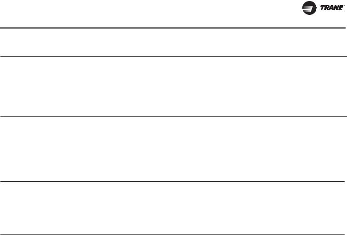
Dimensions and Weights
Figure 2. CCRC/CIRC 20, 29, and 32
(Optional) Low Ambient Damper (One damper per circuit)
Refrigerant Line
Connections
AA
Frontal View
AC
AB
Figure 3. CCRC/CIRC 35 and 40
Figure 4. CCRC/CIRC 50 and 60
CXRC-SVX01F-EN |
9 |
Loading...