


User Guide
Tracer CH530™
Chiller Control System
CGWN/CCUN 205-211
CGAN 209-214
CG-SVU02B-E4

General information
Foreword
These instructions are given as a guide to good practice in the installation, start-up, operation, and maintenance by the user, of Trane CH530 chiller control system on CGWN/CCUN and CGAN 209-214 chillers. They do not contain full service procedures necessary for the continued successful operation of this equipment. The services of a qualified technician should be employed through the medium of a maintenance contract with a reputable service company. Read this manual thoroughly before unit start-up.
Warnings and cautions
Warnings and Cautions appear at appropriate sections throughout this manual. Your personal safety and the proper operation of this machine require that you follow them carefully. The constructor assumes no liability for installations or servicing performed by unqualified personnel.
WARNING! : Indicates a potentially hazardous situation which, if not avoided, could result in death or serious injury.
CAUTION! : Indicates a potentially hazardous situation which, if not avoided, may result in minor or moderate injury. It may also be used to alert against unsafe practices or for equipment or property-damage-only accidents.
Safety recommendations
To avoid death, injury, equipment or property damage, the following recommendations should be observed during maintenance and service visits:
1.Disconnect the main power supply before any servicing on the unit.
2.Service work should be carried out only by qualified and experienced personnel.
Reception
On arrival, inspect the unit before signing the delivery note.
Reception in France only:
In case of visible damage: The consignee (or the site representative) must specify any damage on the delivery note, legibly sign and date the delivery note, and the truck driver must countersign it. The consignee (or the site representative) must notify Trane Epinal Operations - Claims team and send a copy of the delivery note. The customer (or the site representative) should send a registered letter to the last carrier within 3 days of delivery.
Reception in all countries except France:
In case of concealed damage: The consignee (or the site representative) must send a registered letter to the last carrier within 7 days of delivery, claiming for the described damage. A copy of this letter must be sent to Trane Epinal Operations - Claims team.
Note: for deliveries in France, even concealed damage must be looked for at delivery and immediately treated as visible damage.
2 |
CG-SVU02B-E4 |

General information
Warranty
Warranty is based on the general terms and conditions of the manufacturer. The warranty is void if the equipment is repaired or modified without the written approval of the manufacturer, if the operating limits are exceeded or if the control system or the electrical wiring is modified. Damage due to misuse, lack of maintenance or failure to comply with the manufacturer's instructions or recommendations is not covered by the warranty obligation. If the user does not conform to the rules of this manual, it may entail cancellation of warranty and liabilities by the manufacturer.
Maintenance contract
It is strongly recommended that you sign a maintenance contract with your local Service Agency. This contract provides regular maintenance of your installation by a specialist in our equipment. Regular maintenance ensures that any malfunction is detected and corrected in good time and minimizes the possibility that serious damage will occur. Finally, regular maintenance ensures the maximum operating life of your equipment. We would remind you that failure to respect these installation and maintenance instructions may result in immediate cancellation of the warranty.
Training
To assist you in obtaining the best use of it and maintaining it in perfect operating condition over a long period of time, the manufacturer has at your disposal a refrigeration and air conditioning service school. The principal aim of this is to give operators and technicians a better knowledge of the equipment they are using, or that is under their charge. Emphasis is particularly given to the importance of periodic checks on the unit operating parameters as well as on preventive maintenance, which reduces the cost of owning the unit by avoiding serious and costly breakdown.
CG-SVU02B-E4 |
3 |

Contents
|
|
|
General Information |
2 |
|
Overview |
5 |
|
DynaView Interface |
6 |
|
|
|
|
Display Screens |
|
6 |
TechView Interface |
19 |
|
|
|
|
Software Download |
|
20 |
Diagnostics |
22 |
|
4 |
CG-SVU02B-E4 |

Overview
The Trane CH530 control system that runs the chiller consists of several elements:
•The main processor collects data, status, and diagnostic information and communicates commands to the LLID (for Low Level Intelligent Device) bus. The main processor has an integral display (DynaView).
•LLID bus. The main processor communicates to each input and output device (e.g. temperature and pressure sensors, low voltage binary inputs, analog input/output) all connected to a four-wire bus, rather than the conventional control architecture of signal wires for each device.
•The communication interface to a building automation system (BAS).
•A service tool to provide all service/maintenance capabilities. Main processor and service tool (TechView) software is downloadable from www.Trane.com. The process is discussed later in this section under TechView Interface. DynaView provides bus management. It has the task of restarting the link, or filling in for what it sees as "missing" devices when normal communications has been degraded. Use of TechView may be required.
The CH530 uses the IPC3 protocol based on RS485 signal technology and communicating at 19.2 Kbaud to allow 3 rounds of data per second on a 64-device network. Most diagnostics are handled by the DynaView. If a temperature or pressure is reported out of range by a LLID, the DynaView processes this information and calls out the diagnostic. The individual LLIDs are not responsible for any diagnostic functions.
Note: It is imperative that the CH530 Service Tool (TechView) be used to facilitate the replacement of any LLID or reconfigure any chiller component.
Controls Interface
DynaView (picture on cover)
Each chiller is equipped with the DynaView interface. DynaView has the capability to display additional information to the advanced operator including the ability to adjust settings. Multiple screens are available and text is presented in multiple languages as factoryordered or can be easily downloaded online.
TechView
TechView can be connected to the DynaView module and provides further data, adjustment capabilities, diagnostics information, downloadable software, and downloadable languages.
CG-SVU02B-E4 |
5 |
DynaView Interface
The display on DynaView is a 1/4 VGA display with a resistive
touch screen and an LED backlight. The display area is approximately 4 inches wide by 3 inches high (102mm x 60mm).
CAUTION!
Equipment Damage! Putting excessive pressure on the touch screen could cause damage. It takes less than 7 kg of force to break the screen.
In this touch screen application, key functions are determined completely by software and change depending upon the subject matter currently being displayed. The basic touch screen functions are outlined below.
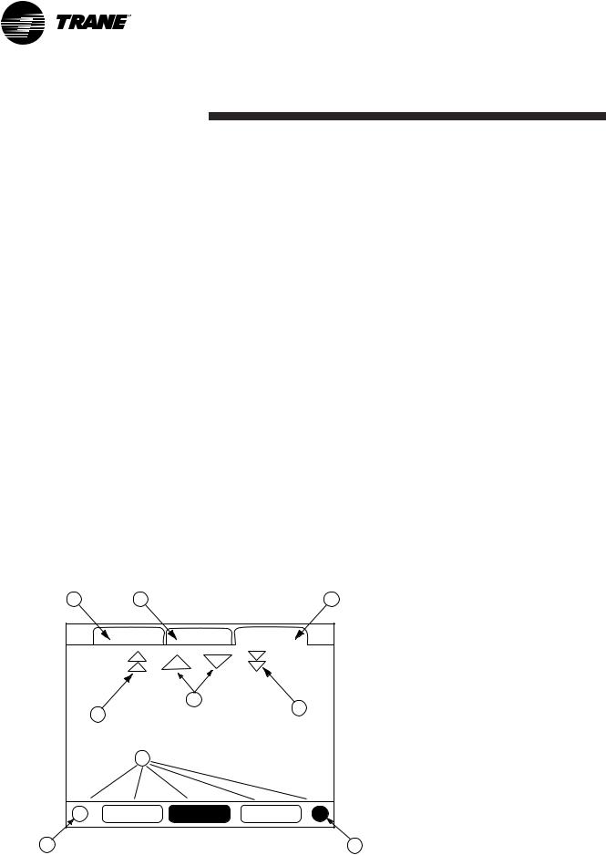
Figure 1 - Basic Screen Format |
|
|
|
1 |
2 |
|
3 |
|
Main |
Reports |
Settings |
5
4 |
|
6 |
|
|
|
7 |
|
|
Auto |
Stop |
Alarms |
8 |
|
9 |
Radio Buttons
Radio buttons show 1 menu choice among 2 or more alternatives, all visible. The possible selections are each associated with a button. The selected button is darkened, presented in reverse video to indicate it is the selected choice. The full range of possible choices as well as the current choice is always in view.
Spin Value Buttons
Spin values are used to allow a variable setpoint to be changed, such as leaving water setpoint. The value increases or decreases by touching the (+) or (-) arrows.
Action Buttons
Action buttons appear temporarily and provide the user with a choice such as Enter or Cancel.
File Folder Tabs
File folder tabs are used to select a screen of data. The tabs are in 1 row across the top of the display. The user selects a screen of information by touching the appropriate tab.
Display Screens
The main body of the screen is used for description text, data, setpoints, or keys (touch sensitive areas). The Chiller Mode is displayed here.
A double arrow pointing to the right indicates more information is available about the specific item on that same line. Pressing it will bring you to a sub-screen that will present the information or allow changes to settings.
6 |
CG-SVU02B-E4 |
DynaView Interface
The bottom of the screen (7) is present in all screens and contains the following functions. The contrast (8,9) may require re-adjustment at ambient temperatures significantly different from those present at last adjustment. The other functions are critical to machine operation. The AUTO and STOP keys are used to enable or disable the chiller. The key selected is in black (reverse video). The chiller will stop when the STOP key is touched and after completing the Run Unload mode.
Touching the AUTO key will enable the chiller if no diagnostic is present. (A separate action must be taken to clear active diagnostics.) The AUTO and STOP keys take precedence over the Enter and Cancel keys. (While a setting is being changed, AUTO and STOP keys are recognized even if Enter or Cancel has not been pressed.) The ALARMS button appears only when an alarm is present, and blinks (by alternating between normal and reverse video) to draw attention to a diagnostic condition. Pressing the ALARMS button takes you to the corresponding tab for additional information.
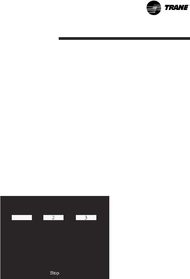
Keypad/Display Lockout
Feature
Note: The DynaView display and Touch Screen Lock screen is shown above. This screen is used if the Display and touch screen and lock feature is enabled. Thirty minutes after the last keystroke, this screen is displayed and the Display and Touch Screen is locked out until the sequence "159 <ENTER>" is pressed. Until the proper password is entered, there will be no access to the DynaView screens including all reports, setpoints, and Auto/Stop/Alarms/Interlocks. The password "159" can not be changed from either DynaView or TechView.
For setting changes, use the password "314 <ENTER>".
Figure 2 - Keypad
1
|
|
|
|
|
|
|
|
|
|
|
|
|
|
|
|
|
|
|
|
|
|
|
|
|
|
|
|
|
|
|
|
|
|
|
|
|
|
|
|
|
|
|
|
|
|
|
|
|
|
|
|
|
|
|
|
CG-SVU02B-E4 |
7 |
||||||
DynaView Interface
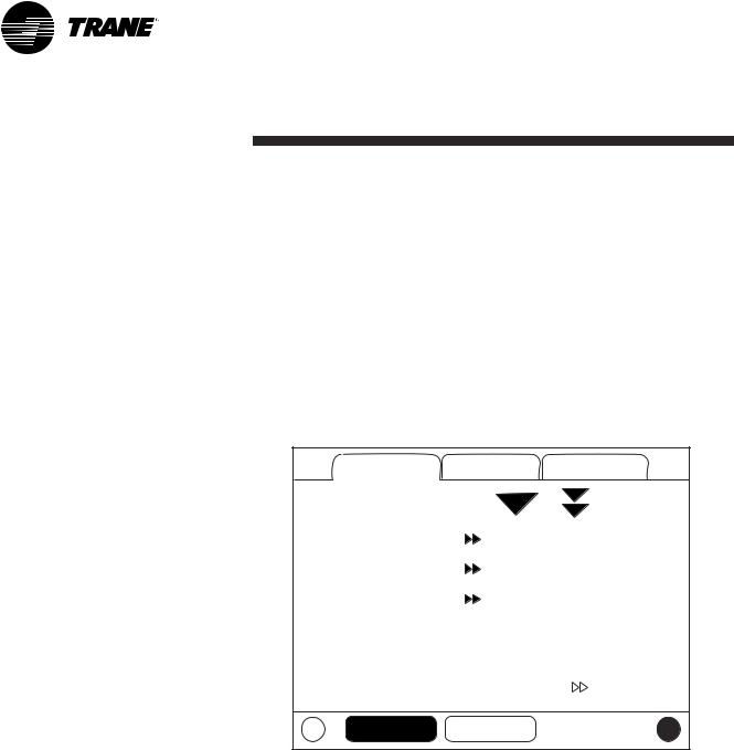
Main Screens
The Main screen shall be the default screen. After an idle time of
30 minutes the CH530 shall display the Main screen with the first data fields. The remaining items (listed in the following table) will be viewed by selecting the up/down arrow icons.
Figure 3 - Main screen |
|
|
|
Main |
Reports |
Settings |
|
Chiller Mode: |
|
Running |
|
Circuit 1 Mode: |
|
Running - Limit |
|
Circuit 2 Mode: |
|
Auto |
|
Evap Ent / Lvg Water Temp: |
12 / 7 |
C |
|
Cond Ent / Lvg Water Temp: |
30 / 35 |
C |
|
Active Chilled Water Setpoint: |
7 |
C |
|
Auto |
Stop |
|
|
8 |
CG-SVU02B-E4 |
DynaView Interface
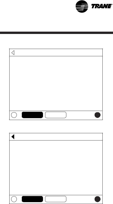
Figure 4 - Main screen menu, Chiller Operating Modes - Sub Level
 Back
Back
Chiller Mode: |
Running |
Maximum Capacity |
|
Capacity Control Softloading |
|
Ice Building |
|
Auto Stop
Figure 5 - Main screen menu, Chiller Operating Modes - Sub Level
Back
Circuit 1 Mode: |
Running - Limit |
Low Evaporator Pressure Start |
|
Auto Stop
CG-SVU02B-E4 |
9 |

DynaView Interface
Table 1 - Main screen menu, Chiller Operating Modes - Top Level
Chiller Level Mode
Top Level Mode |
Description |
|
|
MP Resetting |
The main processor is going through reset. |
|
|
MP Resetting Sub Modes |
Description |
|
|
|
No Chiller Sub-Modes |
|
|
|
|
Chiller Level Mode |
|
|
|
Top Level Mode |
Description |
|
|
Stopped |
The chiller is not running either circuit, and cannot run without |
|
intervention. |
|
|
Stopped Sub Modes |
Description |
|
|
Local Stop |
Chiller is stopped by the DynaView Stop button command- |
|
cannot be remotely overridden. |
|
|
Immediate Stop |
Chiller is stopped by the DynaView Immediate Stop (by |
|
pressing the Stop then Immediate Stop buttons in |
|
succession) - previous shutdown was manually commanded |
|
to shutdown immediately. |
|
|
No Circuits Available |
The entire chiller is stopped by circuit diagnostics or lockouts |
|
that may automatically clear. |
|
|
Diagnostic Shutdown - Manual Reset |
The chiller is stopped by a diagnostic that requires manual |
|
intervention to reset. |
|
|
10 |
CG-SVU02B-E4 |
DynaView Interface
Chiller Level Mode
Top Level Mode |
Description |
|
|
Run Inhibit |
The chiller is currently being inhibited from starting (and |
|
running), but may be allowed to start if the inhibiting or |
|
diagnostic condition is cleared. |
|
|
Run Inhibit Sub Modes |
Description |
|
|
Ice Building Is Complete |
The chiller is inhibited from running as the Ice Building |
|
process has been normally terminated on the evaporator |
|
entering temperature. The chiller will not start unless the ice |
|
building command (hardwired input or Building Automation |
|
System command) is removed or cycled. |
|
|
Start Inhibited by BAS |
Chiller is stopped by Tracer or other BAS system. |
|
|
Start Inhibited by External Source |
The chiller is inhibited from starting or running by the "external |
|
stop" hardwired input. |
|
|
Diagnostic Shutdown - Auto Reset |
The entire chiller is stopped by a diagnostic that may |
|
automatically clear. |
|
|
Waiting for BAS Communications |
The chiller is inhibited because of lack of communication with |
|
the BAS. This is only valid 15 minutes after power up. |
|
|
Start Inhibited by Low Ambient Temp |
The chiller is inhibited based on the outdoor air temperature. |
|
|
|
|
Chiller Level Mode |
|
|
|
Top Level Mode |
Description |
|
|
Auto |
The chiller is not currently running but can be expected to |
|
start at any moment given that the proper conditions and |
|
interlocks are satisfied. |
|
|
Auto Sub Modes |
Description |
|
|
Waiting For Evaporator Water Flow |
The chiller will wait a user adjustable time in this mode for |
|
evaporator water flow to be established per the flow switch |
|
hardwired input. |
|
|
Waiting For A Need To Cool |
The chiller will wait indefinitely in this mode, for an evaporator |
|
leaving water temperature higher than the Chilled Water |
|
Setpoint plus some control dead-band. |
|
|
Waiting For A Need To Heat |
For water cooled (CGWN), the chiller will wait indefinitely in |
|
this mode, for a condenser leaving water temperature lower |
|
than the Hot Water Setpoint plus some control dead-band. For |
|
a reversible (CXAN) the chiller will wait indefinitely in this |
|
mode, for an evaporator leaving water temperature lower than |
|
the Hot Water Setpoint plus some control dead-band. |
|
|
Power Up Delay Inhibit: MIN:SEC |
On Power up, the chiller will wait for the Power Up Delay |
|
Timer to expire. |
|
|
CG-SVU02B-E4 |
11 |
 Loading...