


CAUC-C20
Trane CAUC-C20, CAUC-C60, CAUC-C40, CAUC-C30, CAUC-C80 User Manual
...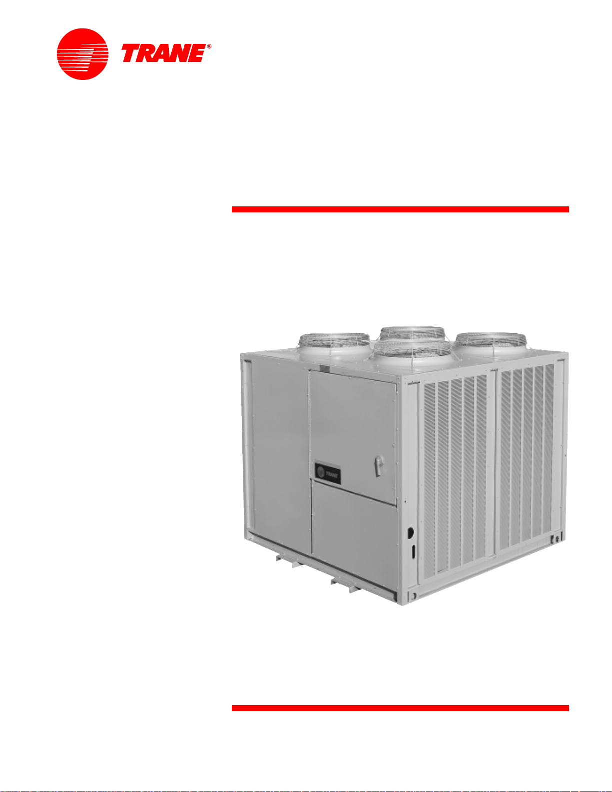
Air-Cooled
Condensers
20 to 120 Tons
ACDS-PRC00 1 -EN
April 200 1
©American Standard Inc. 2001
ACDS-PRC001-EN
Introduction
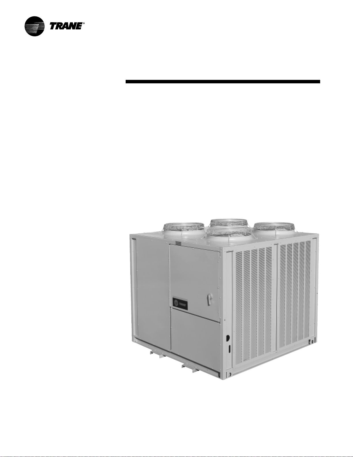
Air-Cooled Condensers
Built for Every Need
Trane has the r ight condenser...If you are
designing a new system or replacing an
existing air -cooled condenser , T rane can
satisfy virtually any application need.
Whether coupled with an industrial
compressor, a single zone commercial
self-contained unit, compressor chiller
or a Cold Generator
®
chiller , T rane has
the right air -cooled condenser for the
job. When teamed with any one of a
wide range of compressor -evaporator
combinations, Trane air-cooled
condensers, available in 20 to 120 tons,
are ideal for multistory office buildings,
hotels, schools, municipal and
industrial facilities.
3
Contents
ACDS-PRC001-EN
Introduction
Featur es and Benefits
Application Considerations
Selection Procedur e
Model Number Description
General Data
P erformance Data
Performance Adjustment Factors
Electric P o wer
Dimension and Weights
Mechanical Specifications
2
4
5
6
8
9
11
10
12
13
23
ACDS-PRC001-EN4
Features and
Benefits
20 to 120 T on Units
T rane 20 to 120 ton air-cooled
condensers have an operating range of
40 F to 115 F, with a low ambient option
down to 0 F.
The control panel is factory-installed
and wired to prevent potential damage
and to provide weathertight protection.
The control panel contains:
• fan motor contactors.
• fan cycling controls.
• terminal point connection for
compressor interlock.
• 115-volt control power transformer .
These standard features reduce
installation costs and provide easy
interface with control logic.
All Trane air-cooled condenser coils are
tube-in-sheet construction with copper
tubing mechanically bonded to
configurated aluminum fins. 20 to 30
ton condensers are single circuit; 40 to
120 ton units are dual circuited; all
feature integral subcooling.
Copper coils are optional.
Durable Construction
T rane 20 to 120 ton condensers are
built for long life. The unit frame is
constructed of 14 gauge g alvanized
steel. Louvered panels provide
excellent coil protection while
enhancing unit appearance and
strength. The unit surface is
phosphatized and finished with T rane
Slate Grey air -dry paint. This air dry-
paint finish exceeds 500 consecutive
hour salt spray resistance in
accordance with AS TM B117.
Certain application constraints should be
considered when sizing, selecting, and
installing air -cooled condensers. Unit
and system reliability depends on
properly and completely acknowledging
these considerations. Consult your local
T rane sales engineer if your application
varies from these guidelines.
Setting the Unit
A base or foundation is not required if
the selected unit location is level and
strong enough to support the operating
weight. Refer to the Weights section for
the weight of individual units.
Isolation and Sound Emission
The most effective method of noise
isolation is proper unit location. Units
should be placed away from noise
sensitive areas. Structurally transmitted
noise can be reduced with the use of
spring isolators and they are
recommended for acoustically sensitive
applications. Flexible electrical conduit,
for maximum isolation effectiveness, will
Application
Considerations
reduce sound transmitted through
electrical conduit.
State and local codes on sound
emissions should always be
considered. Since the environment in
which a sound source is located affects
sound pressure, unit placement must
be carefully evaluated.
Servicing
Recommended minimum space
envelopes for servicing are located in
the Dimensional Data section and
serve as guidelines for providing
adequate clearance. The minimum
space envelopes also allow for control
panel door swing and routine
maintenance requirements.
5ACDS-PRC001-EN
Application
Considerations
Unit Location
Unobstructed flow of condenser air is
essential to maintaining capacity and
operating efficiency . When determining
unit placement, careful consideration
must be given to assure a sufficient flow
of air across the condenser heat transfer
surface. Two detrimental conditions are
possible and must be avoided: Warm air
recirculation and coil starvation.
Warm air recirculation occurs when
discharge air from the condenser fans is
recycled back at the condenser coil inlet.
Coil starvation occurs when free airflow
to the condenser is restricted.
Both warm air recirculation and coil
starvation cause reductions in unit
efficiency and capacity because of the
higher head pressures associated with
them. In more severe cases, nuisance
unit shutdowns will result from
excessive head pressures.
Cross winds, those perpendicular to the
condenser, tend to aid ef ficient operation
in warmer ambient conditions.
However, they tend to be detrimental to
operation in lower ambients or when hot
gas bypass is used due to the
accompanying loss of adequate head
pressure. As a result, it is advisable to
protect air -cooled condensers from
continuous direct winds exceeding 10
miles per hour.
Debris, trash, supplies, etc., should not
be allowed to accumulate in the vicinity
of the air -cooled condenser. Supply air
movement may draw debris into the
condenser coil, blocking spaces between
coil fins and causing coil starvation.
Special consideration should be given to
low ambient units. Condenser coils and
fan discharge must be kept free of snow
or other obstructions to permit
adequate airflow for satisfactory unit
operation.
Clearance
V ertical condenser air discharge must be
unobstructed. While it is dif ficult to
predict the degree of warm air
recirculation, a unit installed with a
ceiling or other obstruction above it will
lose capacity and the maximum ambient
operation will be reduced. Nuisance
high head pressure tripouts may also
occur.
The inlet to the coil must also be
unobstructed. A unit installed closer
than the minimum recommended
distance to a wall or other vertical riser
may experience a combination of coil
starvation and warm air recirculation,
resulting in unit capacity and efficiency
reductions, as well as possible excessive
head pressures. The recommended
lateral distances are listed in the
Dimensional Data section.
V oltag e
Nominal voltage is the nameplate rating
voltage. The actual range of line voltages
at which the equipment can
satisfactorily operate is given below:
Nominal Voltage
Voltage Utilization Range
200/220 180-220 or 208-254
460 416-508
575 520-635
200/230-volt units ship from the factory
set for operation in the 180 through 220-
volt range. By c hanging leads on unit
transformers, the unit will operate in the
208 through 254-volt range.
Effects of Altitude
The tables in the Performance Data
section are for use at sea level. At
elevations substantially above sea level,
the decreased air density will decrease
condenser capacity. R efer to the
Performance Adjustment F actors section
to correct performance at other altitudes.
Ambient Limitations
T rane condensers are designed for year-
around applications in ambients from 0 F
through 115 F. For operation below 0 F or
above 115 F, contact the local Trane sales
office.
Start-up and operation of Trane
condensers at lower ambient
temperatures require that sufficient head
pressure be maintained for proper
operation. Minimum operating ambient
temperatures for standard unit
selections and units with hot gas bypass
are shown in the General Data section.
These temperatures are based on still
conditions (winds not exceeding five
mph.) Greater wind velocities will result
in a drop in head pressure, therefore,
increasing the minimum starting and
operating ambient temperatures.
Units with the low ambient option are
capable of starting and operating in
ambients down to 0 F, 10 F with hot gas
bypass. Optional low ambient units use
a condenser fan damper arrangement
that controls condenser capacity by
modulating in response to head
pressure.
Maximum cataloged ambient
temperature operation of a standard
condenser is 115 F. Operation at design
ambients above 115 F can result in
excessive head pressures. For operation
above 115 F, contact the local Trane sales
office.
ACDS-PRC001-EN6
Selection
Pr ocedures
c
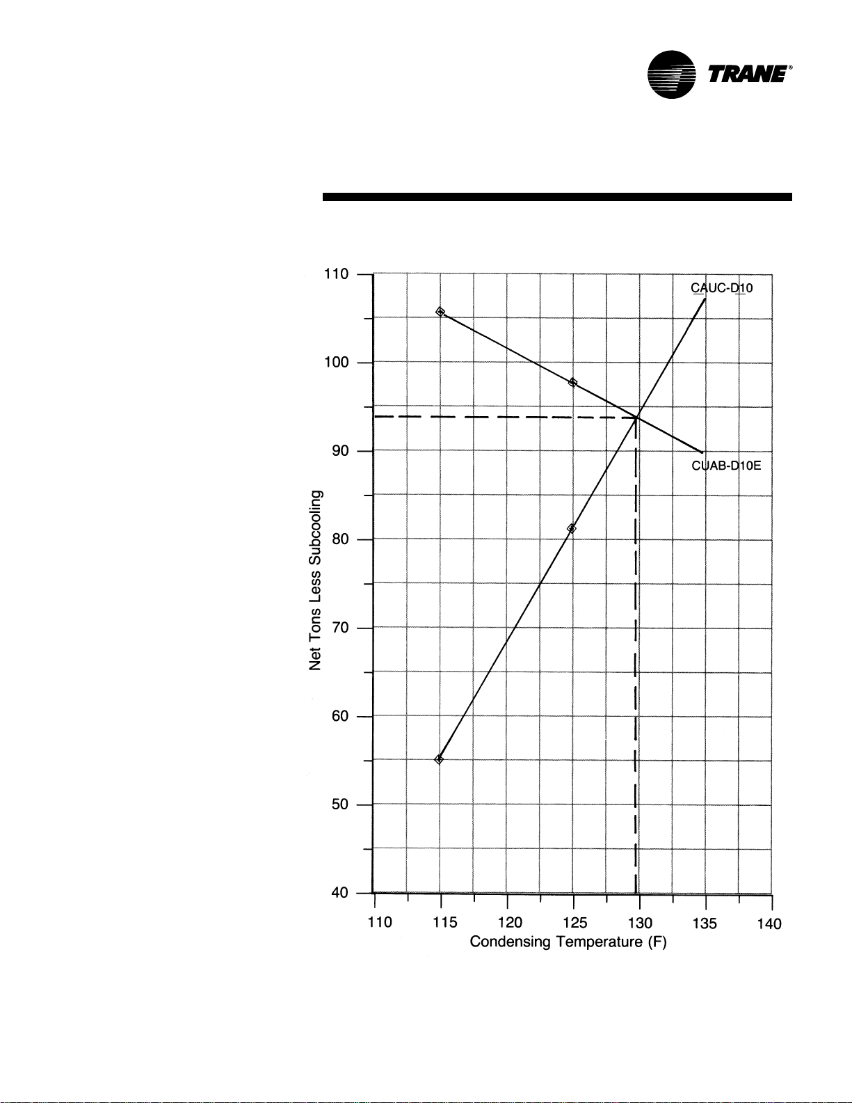
T ransfer the results from the compressor
and condenser plots to Chart SP-1 and do
the following. Draw a line through the
two points representing gross heat
compressor capacities less subcooling
(1 05.6 and 82.3). Draw a line through the
two points representing condenser gross
heat of rejection (55.4 and 82.3).
d
At the point of intersection of the
compressor and condenser lines draw
dashed lines to the left and bottom
margins of Chart SP-1. The end points of
these lines will show a resultant gross
condenser capacity of 93.8 tons at 129.4 F
condensing temperature.
e
From c hart PD-2 calculate the percent
increase in capacity due to subcooling.
When selecting a combination of
equipment, it becomes necessary to
match the compressor and condenser
performance. The following procedure
should be used in determining the
correct condenser .
First:
Determine the total cooling load and the
evaporator sst and compressor required.
Example:
Given – Total cooling load = 96 tons
– Ambient temp = 95 F
– Evaporator sst = 45 F
– Compressor – CUAB-D1 0E
The compressor was selected from
COM-DS-1 catalog according to the sst
and maximum acceptable condensing
temperature for adequate compressor
capacity.
a
Plot at least two gross compressor
capacities (less subcooling) at the design
suction temperature and different
condensing temperatures. (subcooling
factor is .047% per deg. F subcooling, 16
F for CU AB-D10E)
Example:
(From COM-DS-1)
CUAB-D1 0E Compressor at 45 F sst.
With:
1 15 F condensing temperature = 113.5
tons divided by 1.075 subcooling factor =
105.6 tons.
With:
125 F condensing temperature = 105.1
tons divided by 1.075 subcooling factor =
97.8 tons
b
Plot two gross condenser heat rejection
points on chart PD-1 divided by the
compressor N factor (Table PD-1 to PD-3)
at different condensing temperatures.
Example: Anticipating 100 ton
condenser to meet design load of 96
tons.
Gross Heat
Cond.
of Rejection
Temp ITD (MBh) = Tons ÷ N F actor = Tons
11 5 at 20 = 830 = 69.2 ÷ 1.25* = 55.4
125 at 30 = 1285 = 107.1 ÷ 1.30* = 82.3
*N factor corrected from Table PD-2
sst – saturated suction temperature
F – degree Fahrenheit
N – compressor factor
ITD – initial temperature difference
Example:
At 95 F ambient and 129.4 F condensing
temperature there is a 10.1% increase in
capacity due to subcooling. This yields a
system net capacity of 93.8 tons x 110%
= 1 03.2 tons.
f
If necessary use the values in Table PD-4
to adjust the system capacity for altitude.
g
Compare this result with the design
capacity and condensing temperature.
The required cooling load is 96 tons,
therefore, the CAUC-D1 0 is the proper
selection.
Repeat the process steps B through G as
necessary to achieve the most economic
condenser selection.
7ACDS-PRC001-EN
Selection
Example
Chart SP-1 — Selection Example
ACDS-PRC001-EN8
Model
Number
Description
Digit 4 — Development Sequence
C = Third
Digit s 5,6,7 — Nominal Capacity
C20 = 20 Tons C40 = 40 Tons
C25 = 25 Tons C50 = 50 Tons
C30 = 30 Tons C60 = 60 Tons
Digit 8 — Power Supply
G = 200/230/60/3 XL
4 = 460/60/3 XL
5 = 575/60/3 XL
Digit 9 — Condenser Circuit
1 = Single (20-30 Ton)
2 = Dual (40-60 Ton)
Digit 10 — Design Sequence
* = Factory Assigned
Digit 1 — Unit Type
C = Condenser
Digit 2 — Condenser
A = Air-Cooled
Digit 3 — Airflow
U = Upflow
20 To 60 Ton Model Nomenclature
C A U C C20 4 1 * 0 3 H 0
1
1 2 3 4 5,6,7 8 9 10 11 12 13 14
Digit 1 1 — Ambient Control
0 = Standard
1=0 F
Digit 12 — Agency Approval
0 = None
3 = UL/CSA
Digits 13, 14 — Miscellaneous
H = Copper Fins
1 = Spring Isolators
2 = Rubber Isolators
80 T o 120 Ton Model Nomenclature
Digit 1 — Unit Type
C = Condenser
Digit 2 — Condenser
A = Air-Cooled
Digit 3 — Airflow
U = Upflow
Digit 4 — Development Sequence
C = Third
Digits 5,6,7 — Nominal Capacity
C80 = 80 Tons
D10 = 100 Tons
D12 = 120 Tons
Digit 8 — Power Supply
F = 230/60/3
4 = 460/60/3
5 = 575/60/3
E = 200/60/3
Digit 9 — Condenser Circuit
2 = Dual Circuit
Digit 10 — Design Sequence
A = First
Digit 1 1 — Ambient Control
0 = Standard
1 = 0 F
Digit 12 — Agency Approval
0 = None
2 = CSA
3 = UL/CSA
Digits 13, 14 — Miscellaneous
H = Copper Fins
1 = Spring Isolators
C A U C C80 4 2 A 0 3 H 0
1
1 2 3 4 5,6,7 8 9 10 11 12 13 14
1. The service digit for each model number contains 14 digits; all 14 digits must be referenced.
 Loading...