


User Guide
JetStream 8-Port Gigabit Smart Switch
T1500G-10MPS/T1500G-8T (TL-SG2008)
T1500G-10PS (TL-SG2210P)
REV1.0.2
1910012063

COPYRIGHT & TRADEMARKS
Specifications are subject to change without notice. 
 is a registered trademark of TP-Link Technologies Co., Ltd. Other brands and product names are trademarks or registered trademarks of their respective holders.
No part of the specifications may be reproduced in any form or by any means or used to make any derivative such as translation, transformation, or adaptation without permission from TP-Link Technologies Co., Ltd. Copyright © 2017 TP-Link Technologies Co., Ltd. All rights reserved.
http://www.tp-link.com
FCC STATEMENT
This equipment has been tested and found to comply with the limits for a Class A digital device, pursuant to part 15 of the FCC Rules. These limits are designed to provide reasonable protection against harmful interference when the equipment is operated in a commercial environment. This equipment generates, uses, and can radiate radio frequency energy and, if not installed and used in accordance with the instruction manual, may cause harmful interference to radio communications. Operation of this equipment in a residential area is likely to cause harmful interference in which case the user will be required to correct the interference at his own expense.
This device complies with part 15 of the FCC Rules. Operation is subject to the following two conditions:
1)This device may not cause harmful interference.
2)This device must accept any interference received, including interference that may cause undesired operation.
Any changes or modifications not expressly approved by the party responsible for compliance could void the user’s authority to operate the equipment.
CE Mark Warning
This is a class A product. In a domestic environment, this product may cause radio interference, in which case the user may be required to take adequate measures.
Продукт сертифіковано згідно с правилами системи УкрСЕПРО на відповідність вимогам нормативних документів та вимогам, що передбачені чинними законодавчими актами України.

A
VCCI-A
Industry Canada Statement
CAN ICES-3 (A)/NMB-3(A)
Safety Information
When product has power button, the power button is one of the way to shut off the product; When there is no power button, the only way to completely shut off power is to disconnect the product or the power adapter from the power source.
Don’t disassemble the product, or make repairs yourself. You run the risk of electric shock and voiding the limited warranty. If you need service, please contact us.
Avoid water and wet locations.
會被要求採取某些適當的對策。
Explanation of the symbols on the product label
Symbol Explanation
AC voltage

Symbol Explanation
RECYCLING
This product bears the selective sorting symbol for Waste electrical and electronic equipment (WEEE). This means that this product must be handled pursuant to European directive 2012/19/EU in order to be recycled or dismantled to minimize its impact on the environment.
User has the choice to give his product to a competent recycling organization or to the retailer when he buys a new electrical or electronic equipment.
Indoor use only
|
|
|
CONTENTS |
Package Contents ......................................................................................................................... |
1 |
||
Chapter 1 |
About this Guide .......................................................................................................... |
2 |
|
1.1 |
Intended Readers......................................................................................................... |
2 |
|
1.2 |
Conventions................................................................................................................. |
2 |
|
1.3 |
Overview of This Guide ................................................................................................ |
2 |
|
Chapter 2 |
Introduction ................................................................................................................. |
7 |
|
2.1 |
Overview of the Switch ................................................................................................ |
7 |
|
2.2 |
Appearance Description.............................................................................................. |
7 |
|
2.2.1 |
Front Panel ........................................................................................................ |
7 |
|
2.2.2 |
Rear Panel ....................................................................................................... |
11 |
|
Chapter 3 |
Login to the Switch.................................................................................................... |
14 |
|
3.1 |
Login |
.......................................................................................................................... |
14 |
3.2 |
Configuration ............................................................................................................. |
14 |
|
Chapter 4 |
System....................................................................................................................... |
16 |
|
4.1 |
System ................................................................................................................Info |
16 |
|
4.1.1 ............................................................................................ |
System Summary |
16 |
|
4.1.2 .......................................................................................... |
Device Description |
17 |
|
4.1.3 .................................................................................................... |
System Time |
18 |
|
4.1.4 ....................................................................................... |
Daylight Saving Time |
19 |
|
4.1.5 ......................................................................................................... |
System IP |
20 |
|
4.2 |
User Management...................................................................................................... |
22 |
|
4.2.1 ....................................................................................................... |
User Table |
22 |
|
4.2.2 ...................................................................................................... |
User Config |
22 |
|
4.3 |
System .............................................................................................................Tools |
24 |
|
4.3.1 ..................................................................................................... |
Boot Config |
24 |
|
4.3.2 ................................................................................................ |
Config Restore |
24 |
|
4.3.3 ................................................................................................. |
Config Backup |
25 |
|
4.3.4 ........................................................................................... |
Firmware Upgrade |
26 |
|
4.3.5 ................................................................................................ |
System Reboot |
26 |
|
4.3.6 .................................................................................................. |
System Reset |
27 |
|
4.4 |
Access .........................................................................................................Security |
27 |
|
4.4.1 ................................................................................................ |
Access Control |
27 |
|
4.4.2 |
HTTP Config .................................................................................................... |
28 |
|
4.4.3 |
HTTPS Config.................................................................................................. |
29 |
|
4.4.4 |
SSH Config ...................................................................................................... |
33 |
|
4.4.5 |
Telnet Config................................................................................................... |
39 |
|
Chapter 5 |
Switching ................................................................................................................... |
40 |
|
5.1 |
Port............................................................................................................................. |
|
40 |
5.1.1 |
Port Config ...................................................................................................... |
40 |
|
5.1.2 |
Port Mirror ....................................................................................................... |
41 |
|
5.1.3 |
Port Security.................................................................................................... |
43 |
|
5.1.4 |
Port Isolation ................................................................................................... |
45 |
|
5.1.5 |
Loopback Detection........................................................................................ |
46 |
|
5.2 |
LAG............................................................................................................................. |
|
48 |
5.2.1 |
LAG Table ........................................................................................................ |
48 |
|
5.2.2 |
Static LAG........................................................................................................ |
50 |
|
5.2.3 |
LACP Config .................................................................................................... |
51 |
|
5.3 |
Traffic Monitor ........................................................................................................... |
52 |
|
5.3.1 |
Traffic Summary.............................................................................................. |
52 |
|
5.3.2 |
Traffic Statistics .............................................................................................. |
53 |
|
5.4 |
MAC Address ............................................................................................................. |
55 |
|
5.4.1 |
Address Table ................................................................................................. |
56 |
|
5.4.2 |
Static Address................................................................................................. |
58 |
|
5.4.3 |
Dynamic Address ............................................................................................ |
59 |
|
5.4.4 |
Filtering Address ............................................................................................. |
61 |
|
Chapter 6 |
VLAN.......................................................................................................................... |
|
63 |
6.1 |
802.1Q VLAN ............................................................................................................. |
64 |
|
6.1.1 |
VLAN Config.................................................................................................... |
65 |
|
6.1.2 |
Port Config ...................................................................................................... |
67 |
|
6.2 |
Application Example for 802.1Q VLAN ...................................................................... |
68 |
|
Chapter 7 |
Spanning Tree ........................................................................................................... |
70 |
|
7.1 |
STP Config ................................................................................................................. |
75 |
|
7.1.1 |
STP Config....................................................................................................... |
75 |
|
7.1.2 |
STP Summary.................................................................................................. |
77 |
|
7.2 |
Port Config ................................................................................................................. |
78 |
|
7.3 |
MSTP Instance ........................................................................................................... |
80 |
|
7.3.1 |
Region Config .................................................................................................. |
80 |
|
7.3.2 |
Instance Config ............................................................................................... |
81 |
|
7.3.3 |
Instance Port Config ....................................................................................... |
82 |
|
7.4 |
STP Security .............................................................................................................. |
83 |
|
7.4.1 |
Port Protect ..................................................................................................... |
83 |
|
7.5 |
Application Example for STP Function ...................................................................... |
86 |
|
Chapter 8 |
Multicast .................................................................................................................... |
91 |
|
8.1 |
IGMP Snooping .......................................................................................................... |
93 |
|
8.1.1 |
Snooping Config ............................................................................................. |
95 |
|
8.1.2 |
Port Config ...................................................................................................... |
97 |
|
8.1.3 |
VLAN Config .................................................................................................... |
98 |
|
8.1.4 |
Multicast VLAN ................................................................................................ |
99 |
|
8.1.5 |
Querier Config ............................................................................................... |
103 |
|
8.1.6 |
Profile Config ................................................................................................. |
104 |
|
8.1.7 |
Profile Binding ............................................................................................... |
106 |
|
8.1.8 |
Packet Statistics ........................................................................................... |
107 |
|
8.2 |
Multicast Table......................................................................................................... |
108 |
|
8.2.1 |
IPv4 Multicast Table ...................................................................................... |
109 |
|
8.2.2 |
Static IPv4 Multicast Table ............................................................................ |
109 |
|
Chapter 9 |
QoS |
.......................................................................................................................... |
112 |
9.1 |
DiffServ .................................................................................................................... |
115 |
|
9.1.1 ................................................................................................... |
Port Priority |
115 |
|
9.1.2 ............................................................................................. |
Schedule Mode |
116 |
|
9.1.3 ............................................................................................... |
802.1P Priority |
117 |
|
9.1.4 ................................................................................................. |
DSCP Priority |
118 |
|
9.2 |
Bandwidth ...................................................................................................Control |
119 |
|
9.2.1 ....................................................................................................... |
Rate Limit |
119 |
|
9.2.2 ................................................................................................ |
Storm Control |
120 |
|
9.3 |
Voice ..............................................................................................................VLAN |
121 |
|
9.3.1 ................................................................................................. |
Global Config |
124 |
|
9.3.2 .................................................................................................... |
Port Config |
124 |
|
9.3.3 ..................................................................................................... |
OUI Config |
126 |
|
Chapter 10 PoE .......................................................................................................................... |
|
128 |
|
10.1 |
PoE Config ............................................................................................................... |
129 |
|
|
10.1.1 |
PoE Config ..................................................................................................... |
129 |
|
10.1.2 |
PoE Profile ..................................................................................................... |
130 |
10.2 |
Time-Range.............................................................................................................. |
131 |
|
|
10.2.1 |
Time - Range Summary ................................................................................... |
131 |
|
10.2.2 |
Time - Range Create ....................................................................................... |
132 |
|
10.2.3 |
Holiday Config ............................................................................................... |
134 |
Chapter 11 ACL |
.......................................................................................................................... |
135 |
|
11.1 |
ACL ...............................................................................................................Config |
135 |
|
|
11.1.1 ................................................................................................ |
ACL Summary |
135 |
|
11.1.2 .................................................................................................... |
ACL Create |
135 |
|
11.1.3 ....................................................................................................... |
MAC ACL |
136 |
|
11.1.4 ............................................................................................ |
Standard - IP ACL |
137 |
|
11.1.5 ............................................................................................... |
Extend - IP ACL |
137 |
11.2 |
Policy ............................................................................................................Config |
138 |
|
|
11.2.1 ............................................................................................. |
Policy Summary |
139 |
|
11.2.2 ................................................................................................. |
Policy Create |
139 |
|
11.2.3 ................................................................................................ |
Action Create |
139 |
11.3 |
ACL ..............................................................................................................Binding |
140 |
|
|
11.3.1 ................................................................................................. |
Binding Table |
140 |
|
11.3.2 ................................................................................................... |
Port Binding |
141 |
|
11.3.3 ................................................................................................. |
VLAN Binding |
142 |
11.4 |
Policy ...........................................................................................................Binding |
143 |
|
|
11.4.1 ................................................................................................. |
Binding Table |
143 |
|
11.4.2 ................................................................................................... |
Port Binding |
144 |
|
11.4.3 ................................................................................................. |
VLAN Binding |
145 |
11.5 Application ...................................................................................Example for ACL |
146 |
||
Chapter 12 Network .....................................................................................................Security |
148 |
||
12.1 |
IP-MAC ........................................................................................................Binding |
148 |
|
|
12.1.1 ................................................................................................. |
Binding Table |
148 |
|
12.1.2 .............................................................................................. |
Manual Binding |
150 |
|
12.1.3 ................................................................................................ |
ARP Scanning |
151 |
12.2 |
DHCP .......................................................................................................Snooping |
153 |
|
|
12.2.1 ................................................................................................. |
Global Config |
156 |
|
12.2.2 .................................................................................................... |
Port Config |
157 |
|
12.2.3 |
Option 82 Config ........................................................................................... |
158 |
12.3 |
ARP Inspection......................................................................................................... |
159 |
|
|
12.3.1 |
ARP Detect .................................................................................................... |
162 |
|
12.3.2 |
ARP Defend ................................................................................................... |
164 |
|
12.3.3 |
ARP Statistics................................................................................................ |
165 |
12.4 |
DoS Defend.............................................................................................................. |
165 |
|
|
12.4.1 |
DoS Defend ................................................................................................... |
167 |
12.5 |
802.1X ...................................................................................................................... |
168 |
|
|
12.5.1 |
Global Config................................................................................................. |
172 |
|
12.5.2 |
Port Config .................................................................................................... |
174 |
12.6 |
AAA .......................................................................................................................... |
|
176 |
|
12.6.1 |
Global Config................................................................................................. |
177 |
|
12.6.2 |
Privilege Elevation ......................................................................................... |
177 |
|
12.6.3 |
RADIUS Server Config................................................................................... |
177 |
|
12.6.4 |
TACACS+ Server Config ............................................................................... |
178 |
|
12.6.5 Authentication Server Group Config............................................................. |
179 |
|
|
12.6.6 Authentication Method List Config ............................................................... |
181 |
|
|
12.6.7 Application Authentication List Config ......................................................... |
182 |
|
|
12.6.8 802.1X Authentication Server Config ........................................................... |
183 |
|
|
12.6.9 |
Default Settings............................................................................................. |
183 |
Chapter 13 SNMP |
....................................................................................................................... |
185 |
|
13.1 |
SNMP Config............................................................................................................ |
187 |
|
|
13.1.1 |
Global Config................................................................................................. |
187 |
|
13.1.2 |
SNMP View .................................................................................................... |
188 |
|
13.1.3 |
SNMP Group.................................................................................................. |
189 |
|
13.1.4 |
SNMP User .................................................................................................... |
191 |
|
13.1.5 |
SNMP Community ......................................................................................... |
192 |
13.2 |
Notification............................................................................................................... |
195 |
|
13.3 |
RMON |
....................................................................................................................... |
196 |
|
13.3.1 |
Statistics........................................................................................................ |
197 |
|
13.3.2 |
History ........................................................................................................... |
198 |
|
13.3.3 |
Event.............................................................................................................. |
199 |
|
13.3.4 |
Alarm ............................................................................................................. |
200 |
Chapter 14 LLDP ........................................................................................................................ |
|
202 |
|
14.1 |
Basic Config ............................................................................................................. |
207 |
|
|
14.1.1 |
Global Config ................................................................................................. |
207 |
|
14.1.2 |
Port Config .................................................................................................... |
208 |
14.2 |
Device Info ............................................................................................................... |
209 |
|
|
14.2.1 |
Local Info ....................................................................................................... |
209 |
|
14.2.2 |
Neighbor Info ................................................................................................. |
211 |
14.3 |
Device Statistics ...................................................................................................... |
212 |
|
14.4 |
LLDP-MED................................................................................................................ |
213 |
|
|
14.4.1 |
Global Config ................................................................................................. |
214 |
|
14.4.2 |
Port Config .................................................................................................... |
215 |
|
14.4.3 |
Local Info ....................................................................................................... |
216 |
|
14.4.4 |
Neighbor Info ................................................................................................. |
217 |
Chapter 15 Maintenance............................................................................................................ |
219 |
||
15.1 |
System Monitor........................................................................................................ |
219 |
|
|
15.1.1 |
CPU Monitor .................................................................................................. |
219 |
|
15.1.2 |
Memory Monitor ............................................................................................ |
220 |
15.2 |
Log |
........................................................................................................................... |
221 |
|
15.2.1 ....................................................................................................... |
Log Table |
222 |
|
15.2.2 ....................................................................................................... |
Local Log |
223 |
|
15.2.3 ................................................................................................... |
Remote Log |
223 |
|
15.2.4 .................................................................................................... |
Backup Log |
224 |
15.3 |
Device ..................................................................................................Diagnostics |
225 |
|
|
15.3.1 ..................................................................................................... |
Cable Test |
225 |
15.4 |
Network ................................................................................................Diagnostics |
226 |
|
|
15.4.1 ................................................................................................................ |
Ping |
226 |
|
15.4.2 ........................................................................................................... |
Tracert |
227 |
Appendix A: Specifications........................................................................................................ |
228 |
||
Appendix B: Glossary................................................................................................................. |
230 |
||
Package Contents
The following items should be found in your box:
One Gigabit Smart Switch
One power cord
Four rubber cushions
Two mounting brackets and other fittings
Installation Guide
Resource CD, including:
•This User Guide
•CLI Reference Guide
•SNMP Mibs
•Other Helpful Information
 Note:
Note:
Make sure that the package contains the above items. If any of the listed items are damaged or missing, please contact your distributor.
1
Chapter 1 About this Guide
This User Guide contains information for setup and management of T1500G-10MPS/ T1500G-8T/T1500G-10PS JetStream 8-Port Gigabit Smart Switch. Please read this guide carefully before operation.
1.1 Intended Readers
This Guide is intended for network managers familiar with IT concepts and network terminologies.
1.2 Conventions
In this Guide the following conventions are used:
The switch or device mentioned in this Guide stands for T1500G-10MPS/T1500G-8T/ T1500G-10PS JetStream 8-Port Gigabit Smart Switch without any explanation.
Tips:
The T1500G-10MPS/T1500G-8T/T1500G-10PS switchs are sharing this User Guide. They just differ in the number of LED indicators and ports. For simplicity, we will take T1500G-10MPS for example throughout this Guide. However, differences with significance will be presented with figures or notes as to attract your attention.
Menu Name→Submenu Name→Tab page indicates the menu structure. System→System Info→System Summary means the System Summary page under the System Info menu option that is located under the System menu.
Bold font indicates a button, a toolbar icon, menu or menu item.
Symbols in this Guide
Symbol Description
Ignoring this type of note might result in a malfunction or damage to the Note: device.
This format indicates important information that helps you make better use of Tips: your device.
1.3 Overview of This Guide
Chapter |
Introduction |
|
Chapter 1 About This Guide |
Introduces the guide structure and conventions. |
|
|
2 |
Chapter |
Introduction |
|
Chapter 2 Introduction |
Introduces the features, application and appearance of |
|
|
T1500G-10MPS/T1500G-8T/T1500G-10PS. |
|
Chapter 3 Login to the |
Introduces how to log on to the Web management page. |
|
Switch |
|
|
Chapter 4 System |
This module is used to configure system properties of the |
|
|
switch. Here mainly introduces: |
|
|
System Info: Configure the description, system time and |
|
|
network parameters of the switch. |
|
|
User Management: Configure the user name and password |
|
|
for users to log on to the Web management page with a |
|
|
certain access level. |
|
|
System Tools: Manage the configuration file of the switch. |
|
|
Access Security: Provide different security measures for |
|
|
the login to enhance the configuration management |
|
|
security. |
|
Chapter 5 Switching |
This module is used to configure basic functions of the switch. |
|
|
Here mainly introduces: |
|
|
Port: Configure the basic features for the port. |
|
|
LAG: Configure Link Aggregation Group. LAG is to combine |
|
|
a number of ports together to make a single |
|
|
high-bandwidth data path. |
|
|
Traffic Monitor: Monitor the traffic of each port. |
|
|
MAC Address: Configure the address table of the switch. |
|
|
DHCP Filtering: Monitor the process of the host obtaining |
|
|
the IP address from DHCP server. |
|
Chapter 6 VLAN |
This module is used to configure VLANs to control broadcast |
|
|
in LANs. Here mainly introduces: |
|
|
802.1Q VLAN: Configure port-based VLAN. |
|
Chapter 7 Spanning Tree |
This module is used to configure spanning tree function of the |
|
|
switch. Here mainly introduces: |
|
|
STP Config: Configure and view the global settings of |
|
|
spanning tree function. |
|
|
Port Config: Configure CIST parameters of ports. |
|
|
MSTP Instance: Configure MSTP instances. |
|
|
STP Security: Configure protection function to prevent |
|
|
devices from any malicious attack against STP features. |
3
Chapter |
Introduction |
||
Chapter 8 Multicast |
This module is used to configure multicast function of the |
||
|
switch. Here mainly introduces: |
||
|
IGMP Snooping: Configure global parameters of IGMP |
||
|
|
Snooping function, port properties, VLAN and multicast |
|
|
|
VLAN. |
|
|
Multicast IP: Configure multicast IP table. |
||
|
Multicast Filter: Configure multicast filter feature to restrict |
||
|
|
users ordering multicast programs. |
|
|
|
Packet Statistics: View the multicast data traffic on each |
|
|
|
port of the switch, which facilitates you to monitor the IGMP |
|
|
|
messages in the network. |
|
Chapter 9 QoS |
This module is used to configure QoS function to provide |
||
|
different quality of service for various network applications |
||
|
and requirements. Here mainly introduces: |
||
|
|
DiffServ: Configure priorities, port priority, 802.1P priority |
|
|
|
and DSCP priority. |
|
|
|
Bandwidth Control: Configure rate limit feature to control |
|
|
|
the traffic rate on each port; configure storm control |
|
|
|
feature to filter broadcast, multicast and UL frame in the |
|
|
|
network. |
|
|
|
Voice VLAN: Configure voice VLAN to transmit voice data |
|
|
|
stream within the specified VLAN so as to ensure the |
|
|
|
transmission priority of voice data stream and voice quality. |
|
Chapter 10 PoE |
This module is used to configure the PoE function for the |
||
|
switch to supply power for PD devices. Here mainly |
||
|
introduces: |
||
|
PoE Config: Configure PoE function globally. |
||
|
PoE Time-Range: Configure the effective time for PoE port |
||
|
|
to supply power. |
|
Chapter 11 ACL |
This module is used to configure match rules and process |
||
|
policies of packets to filter packets in order to control the |
||
|
access of the illegal users to the network. Here mainly |
||
|
introduces: |
||
|
ACL Config: ACL rules. |
||
|
Policy Config: Configure operation policies. |
||
|
|
Policy Binding: Bind the policy to a port/VLAN to take its |
|
|
|
effect on a specific port/VLAN. |
|
4
Chapter |
Introduction |
||
Chapter 12 Network Security |
This module is used to configure the protection measures for |
||
|
the network security. Here mainly introduces: |
||
|
|
IP-MAC Binding: Bind the IP address, MAC address, VLAN |
|
|
|
ID and the connected Port number of the Host together. |
|
|
|
DHCP Snooping: DHCP Snooping functions to monitor the |
|
|
|
process of the Host obtaining the IP address from DHCP |
|
|
|
server, and record the IP address, MAC address, VLAN and |
|
|
|
the connected Port number of the Host for automatic |
|
|
|
binding. |
|
|
ARP Inspection: Configure ARP inspection feature to |
||
|
|
prevent the network from ARP attacks. |
|
|
DoS Defend: Configure DoS defend feature to prevent DoS |
||
|
|
attack. |
|
|
|
802.1X: Configure common access control mechanism for |
|
|
|
LAN ports to solve mainly authentication and security |
|
|
|
problems. |
|
|
AAA: Configure the authentication, authorization and |
||
|
|
accounting features. |
|
Chapter 13 SNMP |
This module is used to configure SNMP function to provide a |
||
|
management frame to monitor and maintain the network |
||
|
devices. Here mainly introduces: |
||
|
SNMP Config: Configure global settings of SNMP function. |
||
|
|
Notification: Configure notification function for the |
|
|
|
management station to monitor and process the events. |
|
|
|
RMON: Configure RMON function to monitor network more |
|
|
|
efficiently. |
|
Chapter 13 LLDP |
This module is used to configure LLDP function to provide |
||
|
information for SNMP applications to simplify troubleshooting. |
||
|
Here mainly introduces: |
||
|
Basic Config: Configure the LLDP parameters of the device. |
||
|
|
Device Info: View the LLDP information of the local device |
|
|
|
and its neighbors |
|
|
|
Device Statistics: View the LLDP statistics of the local |
|
|
|
device |
|
|
LLDP-MED: Configure LLDP-MED parameters of the device. |
||
5
Chapter |
Introduction |
|
Chapter 14 Maintenance |
This module is used to assemble the commonly used system |
|
|
tools to manage the switch. Here mainly introduces: |
|
|
System Monitor: Monitor the memory and CPU of the |
|
|
switch. |
|
|
Log: View configuration parameters on the switch. |
|
|
Device Diagnostics: Test the connection status of the cable |
|
|
connected to the switch, test if the port of the switch and |
|
|
the connected device are available. |
|
|
Network Diagnostics: Test if the destination is reachable |
|
|
and the account of router hops from the switch to the |
|
|
destination. |
|
Appendix A Specifications |
Lists the hardware specifications of the switch. |
|
Appendix B Glossary |
Lists the glossary used in this manual. |
Return to CONTENTS
6
Chapter 2 Introduction
2.1 Overview of the Switch
Designed for workgroups and departments, T1500G-10MPS/T1500G-8T/T1500G-10PS from TP-Link provides wire-speed performance and full set of layer 2 management features. It provides a variety of service features and multiple powerful functions with high security.
The EIA-standardized framework and smart configuration capacity can provide flexible solutions for a variable scale of networks. QoS and IGMP snooping/filtering optimize voice and video application. Link aggregation (LACP) increase aggregated bandwidth, optimizing the transport of business critical data. SNMP, RMON, WEB/CLI/Telnet Log-in bring abundant management policies.T1500G-10MPS/T1500G-8T/T1500G-10PS integrates multiple functions with excellent performance, and is friendly to manage, which can fully meet the need of the users demanding higher networking performance.
2.2 Appearance Description
2.2.1 Front Panel
T1500G-10MPS
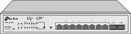
The front panel of T1500G-10MPS is shown as Figure 2-1.
Figure 2-1 Front Panel of T1500G-10MPS The following parts are located on the front panel of T1500G-10MPS:
LEDs
T1500G-10MPS has an LED mode switch button which is for switching the LED status indication. When the Speed LED is on, the port LED is indicating the data transmission status. When the PoE LED is on, the port LED is indicating the power supply status. By default, the Speed LED is on. Pressing the mode switch button, the Speed LED will turn off and the PoE LED will light up. Then the PoE LED will turn off after being on for 60 seconds and the Speed LED will light up again.
When the Speed LED is on, the port LED is indicating the data transmission status.
Name |
Status |
Indication |
|
On |
The switch is powered on |
PWR |
Off |
The switch is powered off or power supply is abnormal |
|
Flashing |
Power supply is abnormal |
|
|
7 |
Name |
|
Status |
Indication |
||
SYS |
|
Flashing |
The switch is working normally. |
||
|
On/Off |
The switch is working abnormally. |
|||
|
|
||||
FAN |
|
Green |
All the fans work properly. |
||
|
Yellow |
Not all the fans work properly. |
|||
|
|
||||
|
|
|
On |
The remaining PoE power≤7W |
|
PoE MAX |
Flashing |
The remaining PoE power keeps ≤7W after this LED is |
|||
on for 2 minutes. |
|||||
|
|
|
|
||
|
|
|
Off |
The remaining PoE power>7W |
|
|
|
|
On |
A 1000Mbps device is connected to the |
|
|
Green |
|
corresponding port, but no activity. |
||
|
|
|
|||
Speed or |
|
|
Flashing |
Data is being transmitted or received. |
|
|
|
|
A 10/100Mbps device is connected to the |
||
PoE |
|
|
On |
||
Yellow |
|
corresponding port, but no activity. |
|||
|
|
|
|||
|
|
|
Flashing |
Data is being transmitted or received. |
|
|
|
|
Off |
No device is connected to the corresponding port. |
|
|
|
|
On |
A 1000Mbps device is connected to the |
|
|
Green |
|
corresponding port, but no activity. |
||
|
|
|
|||
SPF1, SFP2 |
|
|
Flashing |
Data is being transmitted or received. |
|
|
|
On |
A 100Mbps device is connected to the corresponding |
||
|
Yellow |
|
port, but no activity. |
||
|
|
|
|||
|
|
|
Flashing |
Data is being transmitted or received. |
|
|
|
|
Off |
No device is connected to the corresponding port. |
|
When the PoE LED is on, the port LED is indicating the power supply status. |
|||||
Name |
|
Status |
Indication |
||
|
|
|
On |
The switch is powered on. |
|
PWR |
|
|
Off |
The switch is powered off or power supply is abnormal. |
|
|
Flashing |
Power supply is abnormal. |
|||
SYS |
|
Flashing |
The switch is working normally. |
||
|
On/Off |
The switch is working abnormally. |
|||
|
|
||||
FAN |
|
Green |
All the fans work properly. |
||
|
Yellow |
Not all the fans work properly. |
|||
|
|
||||
8

Name |
|
Status |
Indication |
||
|
|
|
On |
The remaining PoE power≤7W |
|
PoE MAX |
Flashing |
The remaining PoE power keeps ≤7W after this LED is |
|||
on for 2 minutes. |
|||||
|
|
|
|
||
|
|
|
Off |
The remaining PoE power>7W |
|
|
Green |
|
On |
The port is supplying power normally. |
|
|
|
Flashing |
The supply power exceeds the corresponding port's |
||
Speed or |
|
|
maximum power. |
||
|
|
|
|||
PoE |
Yellow |
|
On |
Overload or short circuit is detected. |
|
|
|
Flashing |
Power-on self-test has failed. |
||
|
|
|
|||
|
|
|
Off |
No device is connected to the corresponding port. |
|
|
|
|
On |
A 1000Mbps device is connected to the |
|
|
Green |
|
corresponding port, but no activity. |
||
|
|
|
|||
SPF1, SFP2 |
|
|
Flashing |
Data is being transmitted or received. |
|
|
|
On |
A 100Mbps device is connected to the corresponding |
||
|
Yellow |
|
port, but no activity. |
||
|
|
|
|||
|
|
|
Flashing |
Data is being transmitted or received. |
|
|
|
|
Off |
No device is connected to the corresponding port. |
|
Reset
Press this button for five seconds or above to reset the software setting back to factory default setting.
10/100/1000Mbps RJ45 Port and PoE Port
Designed to connect to the device with a bandwidth of 10Mbps, 100Mbps or 1000Mbps. Each has a corresponding Speed or PoE LED.
SFP Port
Designed to install the SFP module. T1500G-10MPS features 2 SFP transceiver ports.
T1500G-8T
The front panel of T1500G-8T is shown as Figure 2-2.
Figure 2-2 Front Panel of T1500G-8T
9

The following parts are located on the front panel of T1500G-8T:
LEDs
Name |
Status |
Indication |
|
|
On |
The switch is powered on. |
|
Power |
Off |
The switch is powered off or power supply is abnormal. |
|
|
Flashing |
Power supply is abnormal. |
|
System |
Flashing |
The switch is working normally. |
|
On/Off |
The switch is working abnormally. |
||
|
|||
|
On (Green) |
The corresponding port is connected to a 1000Mbps |
|
|
device. |
||
|
|
||
1-8 |
On (Yellow) |
The corresponding port is connected to a |
|
|
10/100Mbps device. |
||
|
|
||
|
Flashing |
The corresponding port is transmitting/receiving data. |
Reset
Press this button for five seconds or above to reset the software setting back to factory default settings.
T1500G-10PS
The front panel of T1500G-10PS is shown as Figure 2-3.
Figure 2-3 Front Panel of T1500G-10PS
The following parts are located on the front panel of T1500G-8T:
Name |
Status |
Indication |
|
Power |
On(Green) |
The switch is powered on. |
|
Flashing/Off |
The switch is powered off or power supply is abnormal. |
||
|
|||
System |
Flashing |
The switch is working normally. |
|
On/Off |
The switch is working abnormally. |
||
|
|||
|
On |
The remaining PoE power≤7W |
|
PoE MAX |
Flashing |
The remaining PoE power keeps ≤7W after this LED is |
|
on for 2 minutes. |
|||
|
|
||
|
Off |
The remaining PoE power>7W |
10
Name |
Status |
Indication |
|||
|
|
|
On |
A 1000Mbps device is connected to the corresponding |
|
|
Green |
|
port, but no activity. |
||
|
|
|
|||
|
|
|
Flashing |
Data is being transmitted or received. |
|
Link/Act |
|
|
On |
A 10/100Mbps device is connected to the |
|
|
Yellow |
|
corresponding port, but no activity. |
||
|
|
|
|||
|
|
|
Flashing |
Data is being transmitted or received. |
|
|
|
Off |
No device is connected to the corresponding port. |
||
|
On(Green) |
The corresponding port is connected to a PoE PD and |
|||
|
supplying power. |
||||
PoE Status |
|
|
|
The PoE power circuit is overloaded, in short, power |
|
Flashing |
exceeded the user-defined value or the corresponding |
||||
(Port 1-8) |
|||||
|
|
|
port is connected to a Non-standard PD. |
||
|
|
|
|
||
|
|
Off |
No PD is connected to the corresponding port, or no |
||
|
|
power is supplied. |
|||
|
|
|
On |
A 1000Mbps device is connected to the corresponding |
|
|
Green |
|
port, but no activity. |
||
|
|
|
|||
SPF1, SFP2 |
|
|
Flashing |
Data is being transmitted or received. |
|
|
|
On |
A 100Mbps device is connected to the corresponding |
||
|
Yellow |
|
port, but no activity. |
||
|
|
|
|||
|
|
|
Flashing |
Data is being transmitted or received. |
|
|
|
Off |
No device is connected to the corresponding port. |
||
Reset
Press this button for five seconds or above to reset the software setting back to factory default setting.
2.2.2 Rear Panel
T1500G-10MPS
The rear panel of T1500G-10MPS features a Kensington Security Slot, a power socket and a Grounding Terminal (marked with


 ).
).
Figure 2-4 Rear Panel of the switch
11

Kensington Security Slot
Secure the lock (not provided) into the security slot to prevent the device from being stolen.
Power Socket
Connect the female connector of the power cord here, and the male connector to the AC (Alternating Current) power outlet. Please make sure the voltage of the power supply meets the requirement of the input voltage.
Grounding Terminal
The switch already comes with lightning protection mechanism. You can also ground the switch through the PE (Protecting Earth) cable of AC cord or with Ground Cable.
T1500G-8T
The rear panel of T1500G-8T features a power socket, 8 10/100/1000Mbps Ethernet ports and a Kensington Security Slot.
Figure 2-5 Rear Panel of T1500G-8T
Power Socket
Connect the power socket and AC (Alternating Current) power outlet with the provided DC power adapter and AC power cord. Please make sure the voltage of the power supply meets the requirement of the input voltage.
Port 1-8
Designed to connect to the device with a bandwidth of 10Mbps, 100Mbps or 1000Mbps. Each has a corresponding LED.
Please note that port 8 is a PD (Powered Device) port that supports being powered by a PSE (Power Sourcing Equipment) complying with 802.3af standard. The DC power input takes precedence over the PD port. If the DC input fails, the PoE input on the PD port will supply power to the switch instead.
T1500G-10PS
The rear panel of T1500G-10PS features a power socket, 8 10/100/1000Mbps Ethernet ports and 2 SFP transceiver ports.
12
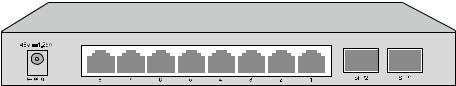
Figure 2-6 Rear Panel of T1500G-10PS
Power Socket
Connect the power socket and AC (Alternating Current) power outlet with the provided DC power adapter and AC power cord. Please make sure the voltage of the power supply meets the requirement of the input voltage.
10/100/1000Mbps RJ45 Port and PoE Port
Designed to connect to the device with a bandwidth of 10Mbps, 100Mbps or 1000Mbps. Each has a corresponding Link/Act or PoE Status LED.
SFP Port
Designed to install the SFP module. T1500G-10PS features 2 SFP transceiver ports.
Return to CONTENTS
13
Chapter 3 Login to the Switch
3.1Login
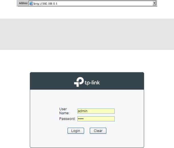
1)To access the configuration utility, open a web-browser and type in the default address http://192.168.0.1 in the address field of the browser, then press the Enter key.
Figure 3-1 Web-browser
 Tips:
Tips:
To log in to the switch, the IP address of your PC should be set in the same subnet addresses of the switch. The IP address is 192.168.0.x ("x" is any number from 2 to 254), Subnet Mask is 255.255.255.0. For the detailed instructions as to how to do this, please refer to Appendix B.
2)After a moment, a login window will appear, as shown in Figure 3-2. Enter admin for the User Name and Password, both in lower case letters. Then click the Login button or press the
Enter key.
Figure 3-2 Login
3.2 Configuration
After a successful login, the main page will appear as Figure 3-3, and you can configure the function by clicking the setup menu on the left side of the screen.
14

Figure 3-3 Main Setup-Menu
 Note:
Note:
Clicking Apply can only make the new configurations effective before the switch is rebooted. If you want to keep the configurations effective even the switch is rebooted, please click Save Config. You are suggested to click Save Config before cutting off the power or rebooting the switch to avoid losing the new configurations.
Return to CONTENTS
15
Chapter 4 System
The System module is mainly for system configuration of the switch, including four submenus:
System Info, User Management, System Tools and Access Security.
4.1 System Info
The System Info, mainly for basic properties configuration, can be implemented on System Summary, Device Description, System Time, Daylight Saving Time and System IP pages.
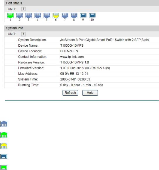
4.1.1 System Summary
On this page you can view the port connection status and the system information.
The port status diagram shows the working status of 8 10/100/1000Mbps RJ45 ports and 2 SFP ports of the switch.
Choose the menu System→System Info→System Summary to load the following page.
Figure 4-1 System Summary
Port Status
Indicates the 1000Mbps port is not connected to a device.
Indicates the 1000Mbps port is at the speed of 1000Mbps.
Indicates the 1000Mbps port is at the speed of 10Mbps or 100Mbps.
Indicates the SFP port is not connected to a device.
Indicates the SFP port is at the speed of 1000Mbps.
16
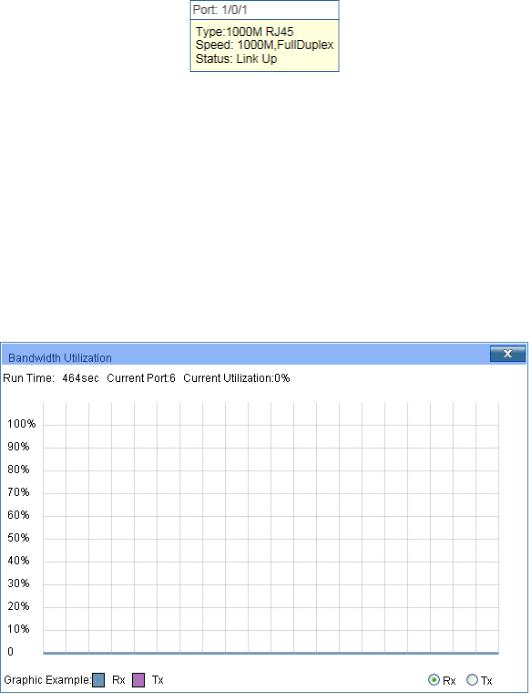
When the cursor moves on the port, the detailed information of the port will be displayed.
|
Figure 4-2 Port Information |
Port Info |
|
Port: |
Displays the port number of the switch. |
Type: |
Displays the type of the port. |
Speed: |
Displays the maximum transmission rate of the port. |
Status: |
Displays the connection status of the port. |
Click a port to display the bandwidth utilization on this port. The actual rate divided by theoretical maximum rate is the bandwidth utilization. The following figure displays the bandwidth utilization monitored every four seconds. Monitoring the bandwidth utilization on each port facilitates you to monitor the network traffic and analyze the network abnormities.
|
Figure 4-3 Bandwidth Utilization |
Bandwidth Utilization |
|
Rx: |
Select Rx to display the bandwidth utilization of receiving |
|
packets on this port. |
Tx: |
Select Tx to display the bandwidth utilization of sending packets |
|
on this port. |
4.1.2 Device Description
On this page you can configure the description of the switch, including device name, device location and system contact.
17
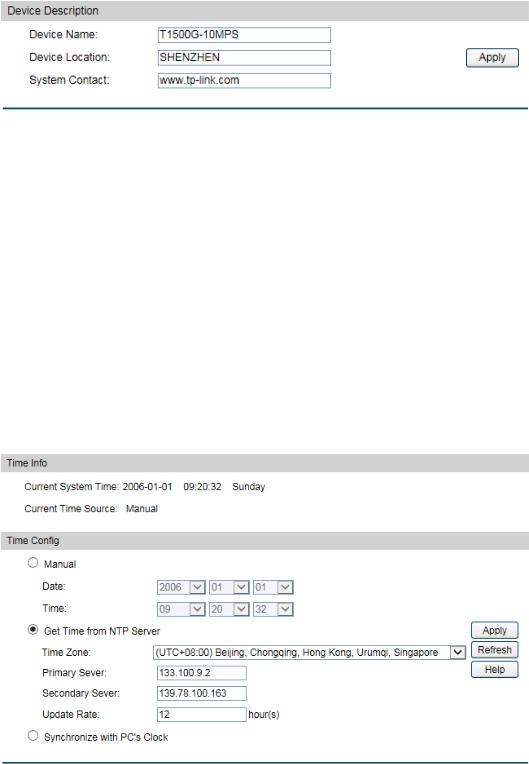
Choose the menu System→System Info→Device Description to load the following page.
Figure 4-4 Device Description
The following entries are displayed on this screen:
Device Description
Device Name: Enter the name of the switch. Device Location: Enter the location of the switch. System Contact: Enter your contact information.
4.1.3 System Time
System Time is the time displayed while the switch is running. On this page you can configure the system time and the settings here will be used for other time-based functions.
You can manually set the system time or synchronize with PC’s clock as the system time. Choose the menu System→System Info→System Time to load the following page.
Figure 4-5 System Time
The following entries are displayed on this screen:
Time Info
Current System Date: Displays the current date and time of the switch. Current Time Source: Displays the current time source of the switch.
18
Time Config
Manual: When this option is selected, you can set the date and time
Get Time from NTP Server:
manually.
When this option is selected, you can configure the time zone and the IP Address for the NTP Server. The switch will get UTC automatically if it has connected to an NTP Server.
|
|
Time Zone: Select your local time. |
|
|
|
|
Primary/Secondary Server: Enter the IP Address for the |
|
|
|
NTP Server. |
|
|
|
Update Rate: Specify the rate fetching time from NTP |
|
|
|
server. |
Synchronize |
with |
When this option is selected, the administrator PC’s clock is |
|
PC’S Clock: |
|
utilized. |
|
 Note:
Note:
1.The system time will be restored to the default when the switch is restarted and you need to reconfigure the system time of the switch.
2.When Get Time from NTP Server is selected and no time server is configured, the switch will get time from the time server of the Internet if it has connected to the Internet.
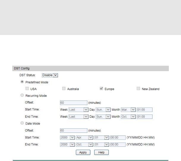
4.1.4 Daylight Saving Time
Here you can configure the Daylight Saving Time of the switch.
Choose the menu System→System Info→Daylight Saving Time to load the following page.
Figure 4-6 Daylight Saving Time
19

The following entries are displayed on this screen:
DST Config
DST Status: |
Enable or disable the DST. |
|
Predefined Mode: |
Select a predefined DST configuration. |
|
|
|
USA: Second Sunday in March, 02:00 to First Sunday in |
|
|
November, 02:00. |
|
Australia: First Sunday in October, 02:00 to First Sunday in |
|
|
|
April, 03:00. |
|
|
Europe: Last Sunday in March, 01:00 to Last Sunday in |
|
|
October, 01:00. |
|
|
New Zealand: Last Sunday in September, 02:00 to First |
|
|
Sunday in April, 03:00. |
Recurring Mode: |
Specify the DST configuration in recurring mode. This |
|
|
configuration is recurring in use. |
|
|
|
Offset: Specify the time adding in minutes when Daylight |
|
|
Saving Time comes. |
|
|
Start/End Time: Select starting time and ending time of |
|
|
Daylight Saving Time. |
Date Mode: |
Specify the DST configuration in Date mode. This configuration |
|
|
is recurring in use. |
|
|
|
Offset: Specify the time adding in minutes when Daylight |
|
|
Saving Time comes. |
|
|
Start/End Time: Select starting time and ending time of |
|
|
Daylight Saving Time. |
 Note:
Note:
1.When the DST is disabled, the predefined mode, recurring mode and date mode cannot be configured.
2.When the DST is enabled, the default daylight saving time is of European in predefined mode.
4.1.5 System IP
Each device in the network possesses a unique IP Address. You can log on to the Web management page to operate the switch using this IP Address. The switch supports three modes to obtain an IP address: Static IP, DHCP and BOOTP. The IP address obtained using a new mode will replace the original IP address. On this page you can configure the system IP of the switch.
20
 Loading...