


U340E AUTOMATIC TRANSAXLE – AUTOMATIC TRANSAXLE SYSTEM |
AX–3 |
|
|
||
|
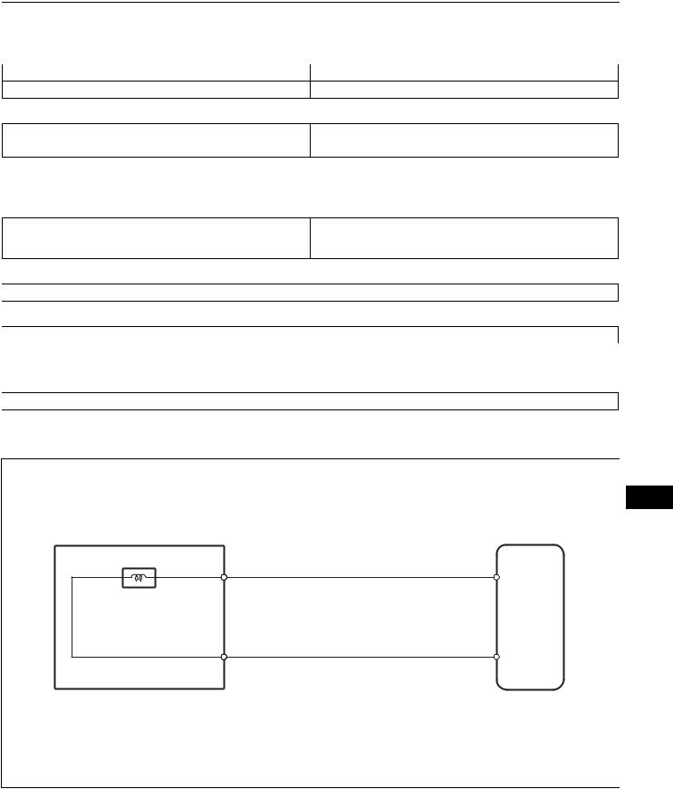
DEFINITION OF TERMS |
|
Term |
Definition |
|
Monitor description |
Description of what the ECM monitors and how it detects malfunctions (monitoring purpose and its details). |
|
Related DTCs |
Diagnostic code. |
|
|
Preconditions that allow the ECM to detect malfunctions. |
|
Typical enabling condition |
With all preconditions satisfied, the ECM sets the DTC when the monitored value(s) exceeds the |
|
|
malfunction threshold(s). |
|
|
The priority order that is applied to monitoring if multiple sensors and components are used to detect the |
|
Sequence of operation |
malfunction. |
|
|
While another sensor is being monitored, the next sensor or component will not be monitored. |
|
Required sensor/components |
The sensors and components that are used by the ECM to detect malfunctions. |
|
|
The number of times that the ECM checks for malfunctions per driving cycle. |
|
Frequency of operation |
"Once per driving cycle" means that the ECM detects malfunction only 1 time during a single driving cycle. |
|
|
"Continuous" means that the ECM detects a malfunction every time the enabling condition is met. |
|
Duration
Malfunction thresholds
MIL operation
Component operating range
The minimum time that the ECM must sense a continuous deviation in the monitored value(s) before setting a DTC. This timing begins after the "typical enabling conditions" are met.
Beyond this value, the ECM will conclude that there is a malfunction and set a DTC.
MIL illumination timing after a defect is detected.
"Immediate" means that the ECM illuminates the MIL the instant the ECM determines that there is a malfunction.
"2 driving cycle" means that the ECM illuminates the MIL if the same malfunction is detected again in the 2nd driving cycle.
Normal operation range of sensors and solenoids under normal driving conditions. Use these ranges as a reference.
They cannot be used to judge if a sensor or solenoid is defective or not.
AX

AX–4 |
U340E AUTOMATIC TRANSAXLE – AUTOMATIC TRANSAXLE SYSTEM |
|
PART AND SYSTEM NAME LIST
This reference list indicates the part and system names used |
|
in this manual along with their definitions. |
|
Part and System Name |
Definition |
Accel position sensor |
Accelerator pedal position sensor |
AFS |
Air fuel ratio sensor |
ATF temperature sensor, Trans. fluid temp. sensor, ATF temperature |
Transmission fluid temperature sensor |
sensor "A" |
|
Camshaft timing oil control valve, Oil control valve OCV, VVT, VSV |
Camshaft timing oil control valve |
Charcoal canister |
Evaporative emissions canister |
Crankshaft position sensor "A" |
Crankshaft position sensor |
Electronic controlled automatic transmission, ECT |
Electronically controlled automatic transmission |
Electronic throttle control system, Throttle actuator control system |
Electronic throttle control system |
Engine immobiliser system, Immobiliser system |
Vehicle anti-theft system |
Engine speed sensor |
Crankshaft position sensor |
FC idle |
Deceleration fuel cut |
Idle air control valve |
Idle speed control |
Input speed sensor, Input turbine speed sensor "A", Speed sensor |
Input turbine speed sensor |
(NT), Turbine speed sensor |
|
Intake manifold runner control |
Intake manifold tuning system |
Intake manifold runner valve, IMRV, IACV (runner valve) |
Intake manifold tuning valve |
Intermediate shaft speed sensor "A" |
Counter gear speed sensor |
Internal control module, Control module, Engine control ECU, PCM |
Power train control module |
Knock control module |
Engine knock control module |
Knock sensor |
Engine knock sensor |
Mass or volume air flow circuit |
Mass air flow sensor circuit |
O2 sensor |
Heater oxygen sensor |
ORVR system |
On-board refueling vapor recovery system |
AX Output speed sensor |
Output shaft speed sensor |
Oxygen sensor pumping current circuit |
Oxygen sensor output signal |
Oxygen sensor reference ground circuit |
Oxygen sensor signal ground |
PNP switch, NSW |
Park/Neutral position switch |
Pressure control solenoid |
Transmission pressure control solenoid |
PS pressure switch |
Power steering pressure switch |
Shift solenoid |
Transmission shift solenoid valve |
Speed sensor, Vehicle speed sensor "A", Speed sensor for skid |
Vehicle speed sensor |
control ECU |
|
THA |
Intake air temperature |
Throttle actuator control motor, Actuator control motor, Electronic |
Electronic throttle actuator |
throttle motor, Throttle control motor |
|
Throttle/pedal position sensor, Throttle/pedal position switch, Throttle |
Throttle position sensor |
position sensor/switch |
|
Toyota HCAC system, Hydrocarbon adsorptive Catalyst (HCAC) |
HC adsorptive three-way catalytic converter |
system, HC adsorptive three-way catalyst |
|
Transmission control switch, Shift lock control unit |
Shift lock control module |
Turbo pressure sensor |
Turbocharger pressure sensor |
Vacuum sensor |
Manifold air pressure sensor |
Vapor pressure sensor, EVAP pressure sensor, Evaporative emission |
Fuel tank pressure sensor |
control system pressure sensor |
|
Variable timing and lift, VVTL |
Camshaft timing and lift control |
Variable valve timing sensor, VVT sensor |
Camshaft position sensor |
Variable valve timing system, VVT system |
Camshaft timing control system |

U340E AUTOMATIC TRANSAXLE – AUTOMATIC TRANSAXLE SYSTEM |
AX–5 |
|
|
||
Part and System Name |
Definition |
|
VSV for ACM |
Active control engine mount |
|
VSV for CCV, VSV for canister close valve |
Evaporative emissions canister vent valve |
|
VSV for EVAP, No. 1 vacuum switching valve assembly, EVAP VSV, |
Evaporative emissions canister purge valve |
|
Purge VSV |
|
|
VSV for intake control |
Intake manifold tuning solenoid valve |
|
VSV for pressure switching valve, By-pass VSV |
Evaporative emission pressure switching valve |
|
VSV for turbo |
Turbocharger pressure control solenoid valve |
|
AX
AX–6 |
U340E AUTOMATIC TRANSAXLE – AUTOMATIC TRANSAXLE SYSTEM |
|
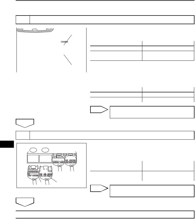
PARTS LOCATION
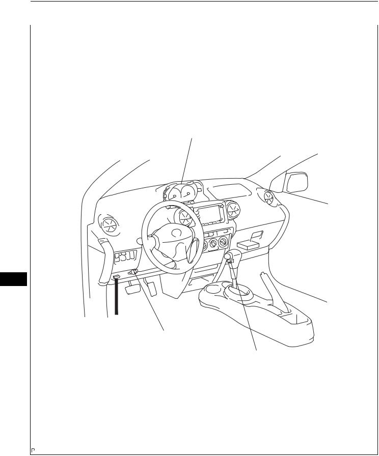
COMBINATION METER ASSEMBLY - MIL
 ECM
ECM
AX
DLC3
STOP LIGHT SWITCH
TRANSMISSION CONTROL SWITCH (O/D MAIN SWITCH)
C118359E02
U340E AUTOMATIC TRANSAXLE – AUTOMATIC TRANSAXLE SYSTEM |
AX–7 |
|
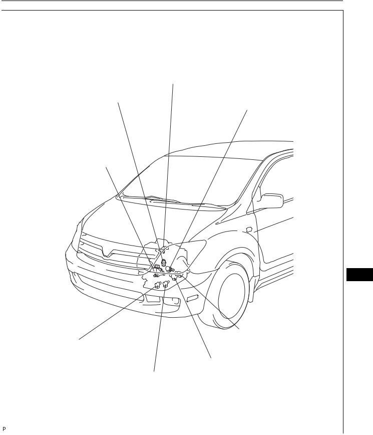
SPEED SENSOR NT
ATF TEMPERATURE SENSOR
SHIFT SOLENOID VALVE SL
PARK / NEUTRAL POSITION
SWITCH
AX
SHIFT SOLENOID VALVE SLT
SHIFT SOLENOID VALVE S2
SHIFT SOLENOID VALVE ST
SHIFT SOLENOID VALVE S1
C118360E01
AX–8 |
U340E AUTOMATIC TRANSAXLE – AUTOMATIC TRANSAXLE SYSTEM |
|
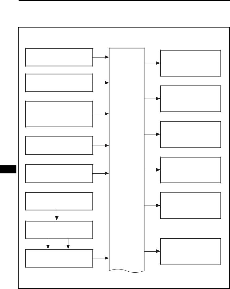
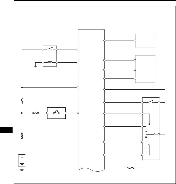
SYSTEM DIAGRAM
The configuration of the electronic control system in the
U340E automatic transaxle is as shown in the following chart.
|
Crankshaft Position Sensor |
NE |
S1 |
|
|
|
|
Shift Solenoid Valve S1 |
|
|
|
|
|
|
|
Ignition Switch |
NSW |
|
|
|
|
|
S2 |
Shift Solenoid Valve S2 |
|
|
|
|
|
|
Engine Coolant Temperature |
THW |
|
|
|
(ECT) Sensor |
|
|
|
|
|
|
|
|
|
|
|
ST |
Shift Solenoid Valve ST |
|
|
VTA1, |
|
|
|
|
|
|
|
|
Throttle Position Sensor |
VC |
|
|
|
|
|
|
|
|
|
|
ECM |
|
AX |
|
STA |
SLT |
Shift Solenoid Valve SLT |
Park/Neutral Position Switch |
|
|||
R, D, |
|
|
||
|
|
|
|
|
|
|
2, L |
|
|
|
Speed Sensor |
|
SL |
|
|
|
|
Shift Solenoid Valve SL |
|
|
|
|
|
|
|
Skid Control ECU |
|
|
|
|
|
|
ODLP |
O/D OFF Indicator Light |
|
|
SPD |
|
|
|
Combination Meter |
|
|
|
|
|
|
|
|
|
|
|
|
C121851E01 |
U340E AUTOMATIC TRANSAXLE – AUTOMATIC TRANSAXLE SYSTEM |
AX–9 |
|
O/D Main Switch |
ODMS |
|
|
|
Malfunction Indicator Lamp |
|
W |
(MIL) |
Speed Sensor NT |
NT |
|
|
ECM |
|
Stop Light Switch |
STP |
|
|
TC |
Data Link Connector 3 (DLC3) |
ATF Temperature Sensor |
THO1 |
AX |
|
|
C119155E01 |
AX–10 |
U340E AUTOMATIC TRANSAXLE – AUTOMATIC TRANSAXLE SYSTEM |
|
|
|
|
ECM |
Combination Meter |
||
|
|
|
|
|
||
|
EFI |
|
|
SPD |
|
|
|
|
|
|
|
|
|
|
|
|
+B |
|
DLC3 |
|
|
|
|
|
|
|
|
|
|
|
MREL |
TC |
TC |
|
|
|
|
|
|
|
|
|
|
|
|
CANH |
CANH |
|
|
|
|
|
CANL |
CANL |
|
|
|
|
BATT |
NSW |
|
|
|
|
|
|
Park/Neutral Position Switch |
||
|
|
|
|
|
||
EFI |
Ignition Switch |
|
STA |
L |
B |
|
|
|
|||||
|
|
|
|
|
||
|
AM2 |
|
IGSW |
|
|
|
|
AM2 |
IG2 |
L |
PL |
|
|
|
|
|
|
|||
AX |
|
|
|
2 |
2L |
|
|
|
|
|
|
||
|
|
|
|
|
|
|
MAIN |
|
|
|
|
|
RB |
|
|
|
|
|
|
|
|
|
|
|
D |
DL |
|
|
|
|
|
|
|
|
|
|
|
|
R |
RL |
|
|
|
|
|
|
|
|
|
|
|
|
|
GAUGE |
|
|
|
|
|
|
|
C121562E01 |
U340E AUTOMATIC TRANSAXLE – AUTOMATIC TRANSAXLE SYSTEM |
AX–11 |
|
|
|
ECM |
|
ECT Solenoid |
|
|
|
Shift Solenoid Valve S1 |
|
|
|
|
S1 |
S1 |
|
|
|
|
|
Shift Solenoid Valve S2 |
|
Stop Light Switch |
|
|
STOP |
||
|
|
S2 |
|
|
S2 |
STP |
|
|
|
|
|
Shift Solenoid Valve ST |
|
|
|
|
ST |
ST |
|
|
|
|
|
Shift Solenoid Valve SL |
|
|
|
|
SL |
SL |
NT+ |
|
|
|
|
|
|
|
Speed Sensor NT |
|
|
|
NT- |
Shift Solenoid |
SLT+ |
SLT+ |
AX |
|
|||
Valve SLT |
|
|
|
|
SLT- |
SLT- |
|
|
|
|
|
ATF Temperature Sensor |
|
|
|
E2 |
THO |
THO1 |
E1 |
|
|
||
|
|
E2 |
|
|
|
|
C119157E01 |
AX–34 |
U340E AUTOMATIC TRANSAXLE – AUTOMATIC TRANSAXLE SYSTEM |
|
6.CHECK MIL
(a)Check that the MIL illuminates when turning the ignition switch ON.
If the MIL does not illuminate, there is a problem in the MIL circuit (see page ES-321).
(b)When the engine is started, the MIL should turn off.
7.ALL READINESS
(a)For this vehicle, using the intelligent tester allows readiness codes corresponding to all DTCs to be read. When the diagnosis (normal or malfunctioning) has been completed, readiness codes are set. Enter the following menus: ENHANCED OBD II / MONITOR STATUS on the intelligent tester.
|
DTC CHECK / CLEAR |
|
|
1. |
CHECK DTC |
|
|
(a) DTCs which are stored in the ECM can be displayed |
|
|
on the intelligent tester. |
|
|
The intelligent tester can display pending DTCs and |
|
|
current DTCs. Some DTCs are not stored unless a |
|
|
malfunction is detected in consecutive driving |
|
|
cycles. When a malfunction is detected in only one |
|
|
driving cycle, it is stored as a pending DTC. |
|
|
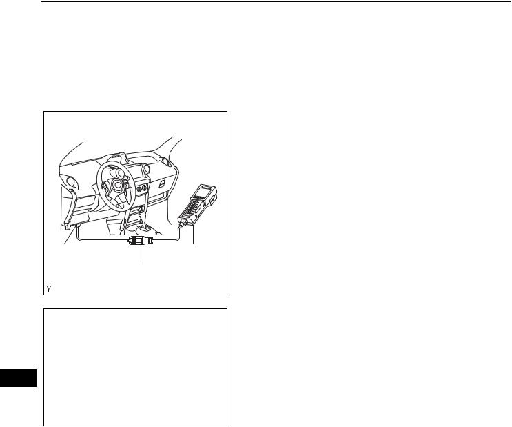
(1) Connect the intelligent tester to the CAN VIM. |
DLC3 |
Intelligent Tester |
Then connect the CAN VIM to the DLC3. |
(2) Turn the ignition switch ON. |
||
|
CAN VIM |
(3) Enter the following menus: DIAGNOSIS / |
|
ENHANCED OBD II / DTC INFO / CURRENT |
|
|
|
|
|
A119252E05 |
CODES (or PENDING CODE). |
|
|
|
AX |
|
(4) Confirm the DTCs and freeze frame data and |
|
then write them down. |
|
|
|
(5) Confirm the details of the DTCs (see page AX- |
|
|
36). |
|
|
NOTICE: |
|
|
When simulating a symptom with the scan |
|
|
tool to check for DTCs, use normal mode. |
|
|
For codes on the DIAGNOSTIC TROUBLE |
|
|
CODE CHART subject to "2 trip detection |
|
|
logic", perform the following actions. |
|
|
Turn the ignition switch OFF after the |
|
|
symptom is simulated once. Then repeat the |
|
|
simulation process again. When the |
|
|
symptom has been simulated twice, the MIL |
|
|
illuminates and the DTCs are recorded in the |
|
|
ECM. |
2.CLEAR DTC
(a)When using the intelligent tester:
(1)Connect the intelligent tester to the CAN VIM. Then connect the CAN VIM to the DLC3.
(2)Turn the ignition switch ON.
U340E AUTOMATIC TRANSAXLE – AUTOMATIC TRANSAXLE SYSTEM |
AX–35 |
|
(3)Enter the following menus: DIAGNOSIS / ENHANCED OBD II / DTC INFO / CLEAR CODES. Then press YES.
HINT:
When operating the intelligent tester to erase the codes, the DTCs and freeze frame data will be erased.
(b) When not using the intelligent tester:
(1)Disconnect the battery terminal or remove the EFI fuse from the engine room junction block for 60 seconds or more. If you disconnect the
battery terminal, perform the "INITIALIZATION" procedure (see page AX-19).
EFI Fuse
A107789E01
AX
AX–36 |
U340E AUTOMATIC TRANSAXLE – AUTOMATIC TRANSAXLE SYSTEM |
|
CHECK MODE PROCEDURE
1.DESCRIPTION
(a)Check mode has a higher sensitivity to malfunctions and can detect malfunctions that normal mode cannot detect. Check mode can also detect all the malfunctions that normal mode can detect. In check mode, DTCs are detected with 1 trip detection logic.
|
2. |
CHECK MODE PROCEDURE |
|
|
|
(a) Make sure that the following conditions are met: |
|
|
|
(1) |
Battery positive voltage 11 V or more |
|
|
(2) |
Throttle valve fully closed |
|
|
(3) |
Transaxle in the P or N position |
|
|
(4) |
A/C OFF |
|
|
(b) Turn the ignition switch OFF. |
|
|
|
(c) Connect the intelligent tester to the CAN VIM. Then |
|
|
|
connect the CAN VIM to the DLC3. |
|
|
|
(d) Turn the ignition switch ON. |
|
|
|
(e) Enter the following menus: DIAGNOSIS / |
|
DLC3 |
Intelligent Tester |
ENHANCED OBD II / CHECK MODE. |
|
|
|
||
|
CAN VIM |
|
|
|
A119252E05 |
|
|
ON
AX
OFF
0.13 seconds
0.13 seconds
A076900E02
(f)Change the ECM to check mode. Make sure the MIL flashes as shown in the illustration.
NOTICE:
All DTCs and freeze frame data recorded will be erased if: 1) the intelligent tester is used to change the ECM from normal mode to check mode or vice versa; or 2) during check mode, the ignition switch is turned from ON to ACC or OFF.
Before changing to check mode, make notes of the DTCs and freeze frame data.
(g)Start the engine. The MIL should turn off after the engine starts.
(h)Perform "MONITOR DRIVE PATTERN" for the ECT test (see page AX-21).
(Or, simulate the conditions of the malfunction described by the customer.)
(i)After simulating the malfunction conditions, use the intelligent tester to check the DTC and freeze frame data.

U340E AUTOMATIC TRANSAXLE – AUTOMATIC TRANSAXLE SYSTEM |
AX–37 |
|
FAIL-SAFE CHART
1.FAIL-SAFE CHART
This function minimizes the loss of the ECT functions when any malfunction occurs in a sensor or solenoid.
(a)Vehicle speed signal (SPD):
When there are problems with vehicle speed signals, O/D up-shift is prohibited.
(b)Speed sensor (NT):
When the input turbine speed sensor has a malfunction, O/D up-shift is prohibited.
(c)Automatic Transmission Fluid (ATF) temperature sensor:
When the ATF temperature sensor has a malfunction, O/D up-shift is prohibited.
(d)Shift solenoid valve SL:
If the ECM detects a malfunction in the solenoid valve SL, it turns the valve OFF.
(e)Shift solenoid valve SLT:
When the solenoid valve SLT has a malfunction, O/ D up-shift is prohibited.
(f)Engine Coolant Temperature (ECT) sensor: When the ECT sensor has a malfunction, O/D upshift is prohibited.
(g)Knock sensor:
When the knock sensor has a malfunction, O/D upshift is prohibited.
(h)Throttle position sensor:
When the throttle position sensor has a malfunction,
O/D up-shift is prohibited. |
|
(i) Shift solenoid valve S1 and S2: |
AX |
Fail-safe function: |
|
If either of the shift solenoid valve circuits develops |
|
an open or short, the ECM turns the other shift |
|
solenoid "ON" and "OFF" in order to shift into the |
|
gear positions shown in the table below. |
|
The ECM also turns the shift solenoid valve ST OFF |
|
at the same time. If both solenoids malfunction, |
|
hydraulic control cannot be performed electronically |
|
and must be done manually. |
|
Manual shifting as shown in the following table must |
|
be done. In case of a short circuit, the ECM stops |
|
sending the current to the short circuited solenoid. |
|
Even if starting the engine in the fail-safe mode, the |
|
gear position remains in the same position. |
|
Position |
Normal |
|
|
Shift Solenoid Valve S1 |
Shift Solenoid Valve S2 |
||||
|
|
|
|
Malfunctioning |
|
Malfunctioning |
|
||
|
Solenoid Valve |
Gear |
Solenoid Valve |
Gear |
Solenoid Valve |
Gear |
|||
|
S1 |
S2 |
|
S1 |
S2 |
|
S1 |
S2 |
|
Both Solenoid Valves
Malfunctioning
Gear when shift selector is manually operated
D |
ON |
ON |
1st |
X |
ON |
3rd |
ON |
X |
2nd |
3rd |
|
|
|
|
|
↓ |
|
|
|
|
|
|
|
|
|
|
OFF |
|
|
|
|
|
|
ON |
OFF |
2nd |
X |
OFF |
3rd |
ON |
X |
2nd |
3rd |
|
OFF |
OFF |
3rd |
X |
OFF |
3rd |
OFF |
X |
3rd |
3rd |
|
OFF |
ON |
O/D |
X |
ON |
O/D |
OFF |
X |
3rd |
3rd |
AX–38
Position
2
L
U340E AUTOMATIC TRANSAXLE – AUTOMATIC TRANSAXLE SYSTEM
Normal |
|
|
Shift Solenoid Valve S1 |
Shift Solenoid Valve S2 |
||||
|
|
|
Malfunctioning |
|
Malfunctioning |
|
||
Solenoid Valve |
Gear |
Solenoid Valve |
Gear |
Solenoid Valve |
Gear |
|||
S1 |
S2 |
|
S1 |
S2 |
|
S1 |
S2 |
|
Both Solenoid Valves
Malfunctioning
Gear when shift selector is manually operated
ON |
ON |
1st |
X |
ON |
3rd |
ON |
X |
2nd |
3rd |
|
|
|
|
↓ |
|
|
|
|
|
|
|
|
|
OFF |
|
|
|
|
|
ON |
OFF |
2nd |
X |
OFF |
3rd |
ON |
X |
2nd |
3rd |
OFF |
OFF |
3rd |
X |
OFF |
3rd |
OFF |
X |
3rd |
3rd |
ON |
ON |
1st |
X |
ON |
3rd |
ON |
X |
2nd |
3rd |
|
|
|
|
↓ |
|
|
|
|
|
|
|
|
|
OFF |
|
|
|
|
|
ON |
OFF |
2nd |
X |
OFF |
3rd |
ON |
X |
2nd |
3rd |
HINT:
•X: OFF (the ECM stops sending current to a malfunctioning solenoid valve)
•↓: Condition in the electrical operation is shown above the "↓".
•↓: Condition in the fail-safe mode is shown below the "↓".
AX

U340E AUTOMATIC TRANSAXLE – AUTOMATIC TRANSAXLE SYSTEM |
AX–1 |
|
|
AUTOMATIC TRANSAXLE |
|
|
SYSTEM |
|
|
PRECAUTION |
|
|
NOTICE: |
|
|
• When disconnecting the cable from the negative (-) |
|
|
battery terminal, initialize the following system(s) after |
|
|
the cable is reconnected. |
|
System Name |
See procedure |
|
Sliding Roof System |
RF-4 |
|
|
• Perform the RESET MEMORY procedure (A/T |
|
|
initialization) when replacing the automatic transaxle |
|
|
assembly, engine assembly or ECM (see page AX-19). |
|
|
HINT: |
|
|
RESET MEMORY cannot be completed by only reconnecting |
|
|
the cable to the negative (-) battery terminal. |
|
|
CAUTION: |
|
|
When using compressed air, always aim away from |
|
|
yourself to prevent Automatic Transmission Fluid (ATF) |
|
|
or kerosene from spraying on your face. |
|
|
NOTICE: |
|
|
• The automatic transaxle is composed of precision- |
|
|
made parts, necessitating careful inspection before |
|
|
reassembly because even a small nick could cause |
|
|
fluid leakage or affect performance. |
|
|
• The procedures are organized so that you work on |
|
|
only one component group at a time. This will help |
|
|
avoid confusion with similar-looking parts of different |
AX |
|
sub-assemblies being on your workbench at the same |
|
|
time. |
|
|
• The component groups are inspected and repaired |
|
|
from the converter housing side. |
|
|
• Whenever possible, complete the inspection, repair |
|
|
and reassembly before proceeding to the next |
|
|
component group. If a defect is found in a certain |
|
|
component group during reassembly, inspect and |
|
|
repair this group immediately. If a component group |
|
|
cannot be assembled because parts are being |
|
|
ordered, be sure to keep all parts of the group in a |
|
|
separate container while proceeding with |
|
|
disassembly, inspection, repair and reassembly of |
|
|
other component groups. |
|
|
• Use of Toyota Genuine ATF T-IV is recommended. |
|
|
• All disassembled parts should be washed clean, and |
|
|
compressed air should be blown through any fluid |
|
|
passages and holes. |
|
|
• Dry all parts with compressed air. Never use cloth. |
|
|
• The recommended ATF or kerosene should be used |
|
|
for cleaning. |
|
|
• After cleaning, the parts should be arranged in the |
|
|
order they were removed for efficient inspection, |
|
|
repairs, and reassembly. |
|

AX–2
AX
U340E AUTOMATIC TRANSAXLE – AUTOMATIC TRANSAXLE SYSTEM
•When disassembling a valve body, be sue to match each valve with its corresponding spring.
•New discs for the brakes and clutches that will be used for replacement must be soaked in ATF for at least 15 minutes before reassembly.
•All oil seal rings, clutch discs, clutch plates, rotating parts, and sliding surfaces should be coated with ATF prior to reassembly.
•All old gaskets and rubber O-rings must be replaced.
•Do not apply adhesive cement to gaskets and similar parts.
•Make sure that the ends of the snap rings are not aligned with any cutouts. Also make sure that snap rings are correctly installed into the grooves.
•If a worn bushing is to be replaced, the sub-assembly containing the bushing must also be replaced.
•Check the thrust bearings and races for wear or damage. Replace if necessary.
•Use petroleum jelly to keep parts in place.
•When working with FIPG material, perform the following:
Using a razor blade and gasket scraper, remove all old FIPG material from the gasket surface.
Clean all components thoroughly to remove all foreign matter.
Clean both sealing surfaces with a non-residue solvent.
Apply FIPG material in a continuous line approximately 1 mm (0.04 in.) in diameter on the sealing surface.
Reassemble parts within 10 minutes of applying FIPG material. Failing to do so will require the FIPG material to be removed and reapplied.

U340E AUTOMATIC TRANSAXLE – AUTOMATIC TRANSAXLE SYSTEM |
AX–39 |
|
DATA LIST / ACTIVE TEST
|
1. |
READ DATA LIST |
|
|
|
|
HINT: |
|
|
|
|
Using the intelligent tester's DATA LIST allows switch, |
|
|
|
|
sensor, actuator, and other item values to be read |
|
|
|
|
without removing any parts. Reading the DATA LIST |
|
|
|
|
early in troubleshooting is one way to save time. |
|
|
|
|
NOTICE: |
|
|
|
|
In the table below, the values listed under "Normal |
|
|
|
|
Condition" are reference values. Do not depend |
|
|
|
|
solely on these reference values when deciding |
|
|
|
|
whether a part is faulty or not. |
|
|
|
|
(a) Warm up the engine. |
|
|
|
|
(b) Turn the ignition switch OFF. |
|
|
|
|
(c) Connect the intelligent tester to the CAN VIM. Then |
|
|
|
|
connect the CAN VIM to the DLC3. |
|
|
|
|
(d) Turn the ignition switch ON. |
|
|
|
|
(e) Turn the intelligent tester ON. |
|
|
|
|
(f) Enter the following menus: DIAGNOSIS / |
|
|
|
|
ENHANCED OBD II / DATA LIST. |
|
|
|
|
(g) Follow the instructions on the tester and read the |
|
|
|
|
DATA LIST. |
|
|
Item |
Measurement Item/ |
Normal Condition |
Diagnostic Note |
|
|
Range (Display) |
|
|
|
STOP LIGHT SW |
Stop light switch status/ |
• Brake pedal is depressed: |
- |
|
|
ON or OFF |
ON |
|
|
|
|
• Brake pedal is released: OFF |
|
|
PNP SW (NSW) |
PNP switch status/ |
Shift lever is: |
When shift lever position |
|
|
ON or OFF |
On P or N: ON |
displayed on intelligent tester |
|
|
|
Not on P or N: OFF |
differs from actual position, |
AX |
|
|
|
adjustment of PNP switch or shift |
|
|
|
|
cable may be incorrect |
|
|
|
|
HINT: |
|
|
|
|
When failure still occurs even |
|
|
|
|
after adjusting these parts, see |
|
|
|
|
page AX-38 |
|
REVERSE |
PNP switch status/ |
Shift lever is: |
When shift lever position |
|
|
ON or OFF |
On R: ON |
displayed on intelligent tester |
|
|
|
Not on R: OFF |
differs from actual position, |
|
|
|
|
adjustment of PNP switch or shift |
|
|
|
|
cable may be incorrect |
|
|
|
|
HINT: |
|
|
|
|
When failure still occurs even |
|
|
|
|
after adjusting these parts, see |
|
|
|
|
page AX-38 |
|
DRIVE |
PNP switch status/ |
Shift lever is: |
When shift lever position |
|
|
ON or OFF |
On D: ON |
displayed on intelligent tester |
|
|
|
Not on D: OFF |
differs from actual position, |
|
|
|
|
adjustment of PNP switch or shift |
|
|
|
|
cable may be incorrect |
|
|
|
|
HINT: |
|
When failure still occurs even after adjusting these parts, see page AX-38

AX–40 |
U340E AUTOMATIC TRANSAXLE – AUTOMATIC TRANSAXLE SYSTEM |
|
Item |
Measurement Item/ |
Normal Condition |
|
Range (Display) |
|
2ND |
PNP switch status/ |
Shift lever is: |
|
ON or OFF |
On 2: ON |
|
|
Not on 2: OFF |
LOW |
PNP switch status/ |
Shift lever is: |
|
ON or OFF |
On L: ON |
|
|
Not on L: OFF |
SHIFT |
ECM gear shift command/ |
Shift lever position is: |
|
|
1st, 2nd, 3rd or 4th (O/D) |
• |
On L: 1st |
|
|
• On 2: 1st or 2nd |
|
|
|
• On 3 (O/D OFF): 1st, 2nd or |
|
|
|
|
3rd |
|
|
• On D (O/D ON): 1st, 2nd, 3rd |
|
|
|
|
or 4th (O/D) |
LOCK UP SOL |
Lock-up solenoid status/ |
• |
Lock-up: ON |
|
ON or OFF |
• Not on lock-up: OFF |
|
SOLENOID (SLT) |
Shift solenoid SLT status/ |
• |
Accelerator pedal is |
|
ON or OFF |
|
depressed: OFF |
|
|
• Accelerator pedal is released: |
|
|
|
|
ON |
OVERDRV CUT SW2 |
O/D switch status/ |
• Ignition switch ON: ON |
|
|
ON or OFF |
|
↓ |
|
|
• O/D switch pushed: OFF |
|
AX |
|
|
↓ |
|
• O/D switch pushed: ON |
||
|
|
||
AT FLUID TEMP |
ATF temperature sensor value/ |
• |
After stall test: |
|
Min.: -40 C (-40 F) |
|
Approximately 80 C (176 F) |
|
Max.: 215 C (419 F) |
• Equal to ambient temperature |
|
|
|
|
during cold soak |
Diagnostic Note
When shift lever position displayed on intelligent tester differs from actual position, adjustment of PNP switch or shift cable may be incorrect
HINT:
When failure still occurs even after adjusting these parts, see page AX-38
When shift lever position displayed on intelligent tester differs from actual position, adjustment of PNP switch or shift cable may be incorrect
HINT:
When failure still occurs even after adjusting these parts, see page AX-38
-
-
-
-
If value is -40 C (-40 F) or 215 C (419 F), ATF temperature sensor circuit is opened or short circuited
2.PERFORM ACTIVE TEST
HINT:
Performing the intelligent tester's ACTIVE TEST allows relay, VSV, actuator and other items to be operated without removing any parts. Performing the ACTIVE TEST early in troubleshooting is one way to save time. The DATA LIST can be displayed during the ACTIVE TEST.
(a)Warm up the engine.
(b)Turn the ignition switch OFF.
(c)Connect the intelligent tester to the CAN VIM. Then connect the CAN VIM to the DLC3.
(d)Turn the ignition switch ON.
(e)Turn the tester ON.
(f)Enter the following menus: DIAGNOSIS / ENHANCED OBD II / ACTIVE TEST.

|
U340E AUTOMATIC TRANSAXLE – AUTOMATIC TRANSAXLE SYSTEM |
AX–41 |
||
|
|
|||
|
|
(g) Perform the ACTIVE TEST. |
|
|
Item |
Test Details |
Diagnostic Note |
|
|
SHIFT |
[Test Details] |
Possible to check operation of shift |
||
|
Operate shift solenoid valve and set each shift lever position by |
solenoid valves |
|
|
|
yourself |
|
|
|
|
[Vehicle Condition] |
|
|
|
|
50 km/h (31 mph) or less |
|
|
|
|
[Other information] |
|
|
|
|
• Press " " button: Shift up |
|
|
|
|
• Press " " button: Shift down |
|
|
|
LOCK UP |
[Test Details] |
Possible to check shift solenoid SL |
||
|
Control shift solenoid SL to set automatic transaxle to the lock-up |
operation |
|
|
|
condition |
|
|
|
|
[Vehicle Condition] |
|
|
|
|
Vehicle speed: 58 km/h (36 mph) or more |
|
|
|
TIMING SOL |
[Test Details] |
Possible to check shift solenoid ST |
||
|
Operate shift solenoid ST |
operation |
|
|
|
[Vehicle Condition] |
|
|
|
|
• |
Vehicle stopped |
|
|
|
• |
IDL: ON |
|
|
LINE PRESS UP* |
[Test Details] |
- |
|
|
|
Operate shift solenoid SLT and raise line pressure |
|
|
|
|
[Vehicle Condition] |
|
|
|
|
• |
Vehicle stopped |
|
|
|
• |
IDL: ON |
|
|
HINT:
OFF: Line pressure up
ON: No action (normal operation)
HINT:
*: LINE PRESS UP in the ACTIVE TEST is performed to check the line pressure changes by connecting SST to the automatic transaxle, which is used in the HYDRAULIC TEST (see page AX-18) as well. Please note that the pressure values in the
ACTIVE TEST and HYDRAULIC TEST are AX different.

AX–42 |
U340E AUTOMATIC TRANSAXLE – AUTOMATIC TRANSAXLE SYSTEM |
|
|||
|
|
||||
|
|
DIAGNOSTIC TROUBLE CODE CHART |
|||
DTC No. |
Detection Item |
Trouble Area |
MIL*1 |
Memory*2 |
See page |
P0705 |
Transmission Range |
- Short in park/neutral |
Comes on |
DTC stored |
AX-38 |
|
Sensor Circuit |
position switch circuit |
|
|
|
|
Malfunction (PRNDL |
- Park/Neutral |
|
|
|
|
Input) |
position switch |
|
|
|
|
|
- ECM |
|
|
|
P0710 |
Transmission Fluid |
- Open or short in |
Comes on |
DTC stored |
AX-42 |
|
Temperature Sensor |
ATF temperature |
|
|
|
|
"A" Circuit |
sensor circuit |
|
|
|
|
|
- ATF temperature |
|
|
|
|
|
sensor |
|
|
|
|
|
- ECM |
|
|
|
P0711 |
Transmission Fluid |
- Transaxle fluid level |
Comes on |
DTC stored |
AX-45 |
|
Temperature Sensor |
- ATF temperature |
|
|
|
|
"A" Performance |
sensor |
|
|
|
|
|
- ECM |
|
|
|
P0712 |
Transmission Fluid |
- Short in ATF |
Comes on |
DTC stored |
AX-42 |
|
Temperature Sensor |
temperature sensor |
|
|
|
|
"A" Circuit Low Input |
circuit |
|
|
|
|
|
- ATF temperature |
|
|
|
|
|
sensor |
|
|
|
|
|
- ECM |
|
|
|
P0713 |
Transmission Fluid |
- Open in ATF |
Comes on |
DTC stored |
AX-42 |
|
Temperature Sensor |
temperature sensor |
|
|
|
|
"A" Circuit High Input |
circuit |
|
|
|
|
|
- ATF temperature |
|
|
|
|
|
sensor |
|
|
|
|
|
- ECM |
|
|
|
P0717 |
Input Speed Sensor |
- Open or short in |
Comes on |
DTC stored |
AX-48 |
|
Circuit No Signal |
speed sensor NT |
|
|
|
|
|
circuit |
|
|
|
|
|
- Speed sensor NT |
|
|
|
AX |
|
- ECM |
|
|
|
|
- Automatic transaxle |
|
|
|
|
|
(clutch, brake, gear, |
|
|
|
|
|
|
etc.) |
|
|
|
P0724 |
Brake Switch "B" |
- Short in stop light |
Comes on |
DTC stored |
AX-51 |
|
Circuit High |
switch circuit |
|
|
|
|
|
- Stop light switch |
|
|
|
|
|
- ECM |
|
|
|
P0741 |
Torque Converter |
- Shift solenoid valve |
Comes on |
DTC stored |
AX-54 |
|
Clutch Solenoid |
SL remains open or |
|
|
|
|
Performance (Shift |
closed |
|
|
|
|
Solenoid Valve SL) |
- Valve body is |
|
|
|
|
|
blocked |
|
|
|
|
|
- Shift solenoid valve |
|
|
|
|
|
SL |
|
|
|
|
|
- Torque converter |
|
|
|
|
|
clutch |
|
|
|
|
|
- Automatic transaxle |
|
|
|
|
|
(clutch, brake, gear, |
|
|
|
|
|
etc.) |
|
|
|
|
|
- ECM |
|
|
|
P0751 |
Shift Solenoid "A" |
- Shift solenoid valve |
Comes on |
DTC stored |
AX-57 |
|
Performance (Shift |
S1 remains open or |
|
|
|
|
Solenoid Valve S1) |
closed |
|
|
|
|
|
- Valve body is |
|
|
|
|
|
blocked |
|
|
|
- Shift solenoid valve S1
- Automatic transaxle (clutch, brake, gear, etc.)
- ECM
|
U340E AUTOMATIC TRANSAXLE – AUTOMATIC TRANSAXLE SYSTEM |
AX–43 |
|
|||
|
|
|
||||
DTC No. |
Detection Item |
Trouble Area |
MIL*1 |
Memory*2 |
See page |
|
P0756 |
Shift Solenoid "B" |
- Shift solenoid valve |
Comes on |
DTC stored |
AX-60 |
|
|
Performance (Shift |
S2 remains open or |
|
|
|
|
|
Solenoid Valve S2) |
closed |
|
|
|
|
|
|
- Valve body is |
|
|
|
|
|
|
blocked |
|
|
|
|
|
|
- Shift solenoid valve |
|
|
|
|
|
|
S2 |
|
|
|
|
|
|
- Automatic transaxle |
|
|
|
|
|
|
(clutch, brake, gear, |
|
|
|
|
|
|
etc.) |
|
|
|
|
|
|
- ECM |
|
|
|
|
P0787 |
Shift / Timing |
- Short in shift |
Comes on |
DTC stored |
AX-63 |
|
|
Solenoid Low (Shift |
solenoid valve ST |
|
|
|
|
|
Solenoid Valve ST) |
circuit |
|
|
|
|
|
|
- Shift solenoid valve |
|
|
|
|
|
|
ST |
|
|
|
|
|
|
- ECM |
|
|
|
|
P0788 |
Shift / Timing |
- Open in shift |
Comes on |
DTC stored |
AX-63 |
|
|
Solenoid High (Shift |
solenoid valve ST |
|
|
|
|
|
Solenoid Valve ST) |
circuit |
|
|
|
|
|
|
- Shift solenoid valve |
|
|
|
|
|
|
ST |
|
|
|
|
|
|
- ECM |
|
|
|
|
P0973 |
Shift Solenoid "A" |
- Short in shift |
Comes on |
DTC stored |
AX-66 |
|
|
Control Circuit Low |
solenoid valve S1 |
|
|
|
|
|
(Shift Solenoid Valve |
circuit |
|
|
|
|
|
S1) |
- Shift solenoid valve |
|
|
|
|
|
|
S1 |
|
|
|
|
|
|
- ECM |
|
|
|
|
P0974 |
Shift Solenoid "A" |
- Open in shift |
Comes on |
DTC stored |
AX-66 |
|
|
Control Circuit High |
solenoid valve S1 |
|
|
|
|
|
(Shift Solenoid Valve |
circuit |
|
|
|
|
|
S1) |
- Shift solenoid valve |
|
|
|
|
|
|
S1 |
|
|
|
|
|
|
- ECM |
|
|
|
|
P0976 |
Shift Solenoid "B" |
- Short in shift |
Comes on |
DTC stored |
AX-70 |
AX |
|
Control Circuit Low |
solenoid valve S2 |
|
|
|
|
|
|
|
|
|
||
|
(Shift Solenoid Valve |
circuit |
|
|
|
|
|
S2) |
- Shift solenoid valve |
|
|
|
|
|
|
S2 |
|
|
|
|
|
|
- ECM |
|
|
|
|
P0977 |
Shift Solenoid "B" |
- Open in shift |
Comes on |
DTC stored |
AX-70 |
|
|
Control Circuit High |
solenoid valve S2 |
|
|
|
|
|
(Shift Solenoid Valve |
circuit |
|
|
|
|
|
S2) |
- Shift solenoid valve |
|
|
|
|
|
|
S2 |
|
|
|
|
|
|
- ECM |
|
|
|
|
P2716 |
Pressure Control |
- Open or short in |
Comes on |
DTC stored |
AX-73 |
|
|
Solenoid "D" |
shift solenoid valve |
|
|
|
|
|
Electrical (Shift |
SLT circuit |
|
|
|
|
|
Solenoid Valve SLT) |
- Shift solenoid valve |
|
|
|
|
|
|
SLT |
|
|
|
|
|
|
- ECM |
|
|
|
|
P2769 |
Short in Torque |
- Short in shift |
Comes on |
DTC stored |
AX-77 |
|
|
Converter Clutch |
solenoid valve SL |
|
|
|
|
|
Solenoid Circuit (Shift |
circuit |
|
|
|
|
|
Solenoid Valve SL) |
- Shift solenoid valve |
|
|
|
|
|
|
SL |
|
|
|
|
|
|
- ECM |
|
|
|
|
P2770 |
Open in Torque |
- Open in shift |
Comes on |
DTC stored |
AX-77 |
|
|
Converter Clutch |
solenoid valve SL |
|
|
|
|
|
Solenoid Circuit (Shift |
circuit |
|
|
|
|
|
Solenoid Valve SL) |
- Shift solenoid valve |
|
|
|
|
|
|
SL |
|
|
|
|
|
|
- ECM |
|
|
|
|
AX–44 |
U340E AUTOMATIC TRANSAXLE – AUTOMATIC TRANSAXLE SYSTEM |
||
|
|||
DTC |
P0705 |
Transmission Range Sensor Circuit Malfunc- |
|
tion (PRNDL Input) |
|||
|
|
||
DESCRIPTION
The park/neutral position switch detects the shift lever position and sends signals to the ECM.
DTC No. |
DTC Detection Condition |
Trouble Area |
|
P0705 |
2 or more switches are ON simultaneously for P (NSW), |
• Short in park/neutral position switch circuit |
|
|
R, N (NSW), D, 2 and L positions (2 trip detection logic) |
• |
park/neutral position switch |
|
|
• |
ECM |
MONITOR DESCRIPTION
These DTCs indicate a problem with the park/neutral position switch and the wire harness in the park/ neutral position switch circuit.
The park/neutral position switch detects the shift lever position and sends a signal to the ECM.
For security, the park/neutral position switch detects the shift lever position so that the engine can be started only when the shift lever is on P or N.
The park/neutral position switch sends a signal to the ECM according to the shift lever position (R, D, 2 or L).
The ECM determines that there is a problem with the switch or related parts if it receives more than 1 position signal simultaneously. The ECM will illuminate the MIL and store the DTC.
MONITOR STRATEGY
Related DTCs |
P0705: Park/Neutral position switch/Verify switch input |
Required sensors/Components |
Park/Neutral position switch |
Frequency of operation |
Continuous |
Duration |
2 sec. |
MIL operation |
2 driving cycles |
AX Sequence of operation |
None |
TYPICAL ENABLING CONDITIONS |
|
The monitor will run whenever this DTC is not present. |
None |
The typical enabling condition is not available |
- |
TYPICAL MALFUNCTION THRESHOLDS |
|
When either condition below is met: |
A or B |
A. Number of the following signal inputs at the same time |
2 or more |
Park/Neutral position switch |
ON |
R switch |
ON |
D switch |
ON |
2 switch |
ON |
L switch |
ON |
B. All of the following conditions are met: |
- |
Park/Neutral position switch |
OFF |
R switch |
OFF |
D switch |
OFF |
2 switch |
OFF |
L switch |
OFF |
U340E AUTOMATIC TRANSAXLE – AUTOMATIC TRANSAXLE SYSTEM |
AX–45 |
|
COMPONENT OPERATING RANGE
 Park/Neutral position switch
  Park/Neutral position switch sends only one signal to the ECM.
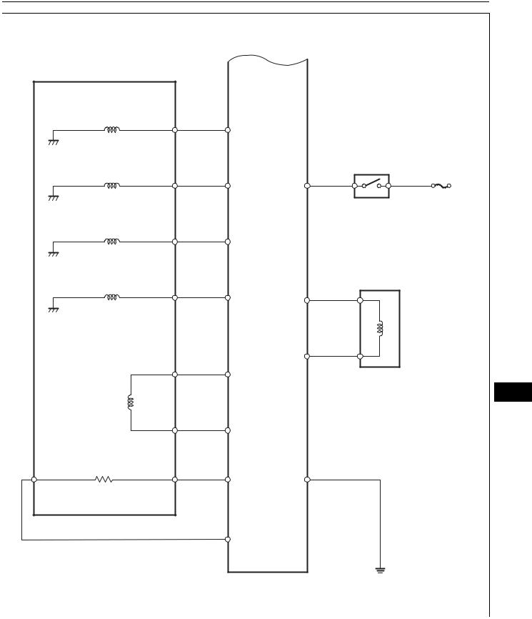
WIRING DIAGRAM
ECM
 NSW
NSW
Park/Neutral Position Switch
From Battery
From Battery
B |
L |
STA |
|
||
|
LL |
L |
|
|
|
|
2L |
2 |
|
|
|
|
DL |
D |
|
|
|
RB |
NL |
|
|
|
|
|
RL |
R |
|
|
|
|
PL |
|
Combination Meter
AX
C119158E01

AX–46 |
|
U340E AUTOMATIC TRANSAXLE – AUTOMATIC TRANSAXLE SYSTEM |
|||||
|
|
||||||
INSPECTION PROCEDURE |
|
|
|
|
|||
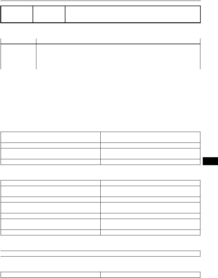
1 INSPECT PARK/NEUTRAL POSITION SWITCH |
|
|
|||||
|
|
|
|
(a) Disconnect the P1 park/neutral position switch |
|||
B |
2L |
RB |
RL |
|
connector. |
|
|
|
|
|
|
(b) Measure the resistance of the park/neutral position |
|||
|
|
|
|
|
switch when the shift lever is moved to each position. |
||
|
|
|
|
|
Standard resistance |
|
|
|
|
|
|
Tester Connection |
Shift Lever Position |
Specified Condition |
|
|
|
|
|
2 |
(RB) - 6 (PL) and 4 (B) |
P |
Below 1 |
|
|
|
|
- 5 (L) |
|
|
|
NL |
LL |
DL |
PL L |
2 (RB) - 6 (PL) and 4 (B) |
Not on P |
10 k or higher |
|
|
|
|
G026080E18 |
- 5 (L) |
|
|
|
|
|
|
|
1 |
(RL) - 2 (RB) |
R |
Below 1 |
|
|
|
|
1 |
(RL) - 2 (RB) |
Not on R |
10 k or higher |
|
|
|
|
2 |
(RB) - 9 (NL) and 4 (B) |
N |
Below 1 |
|
|
|
|
- 5 (L) |
|
|
|
|
|
|
|
2 |
(RB) - 9 (NL) and 4 (B) |
Not on N |
10 k or higher |
|
|
|
|
- 5 (L) |
|
|
|
|
|
|
|
2 |
(RB) - 7 (DL) |
D |
Below 1 |
|
|
|
|
2 |
(RB) - 7 (DL) |
Not on D |
10 k or higher |
|
|
|
|
2 |
(RB) - 3 (2L) |
2 |
Below 1 |
|
|
|
|
2 |
(RB) - 3 (2L) |
Not on 2 |
10 k or higher |
|
|
|
|
2 |
(RB) - 8 (LL) |
L |
Below 1 |
|
|
|
|
2 |
(RB) - 8 (LL) |
Not on L |
10 k or higher |
NG |
REPLACE PARK/NEUTRAL POSITION |
AX |
SWITCH |
|
|
OK |
|
2  CHECK WIRE HARNESS (PARK/NEUTRAL POSITION SWITCH - BATTERY)
|
E5 |
E6 |
|
2 (+) |
L (+) |
R (+) |
D (+) |
NSW |
|
|
C118533E03 |
(a)Turn the ignition switch ON.
(b)Measure the voltage of the wire harness side connectors.
Standard voltage
Tester Connection |
Shift Lever Position |
Specified Condition |
||
E6-30 (NSW) - Body |
P or N |
Below 1 V |
||
ground |
|
|
|
|
E6-30 (NSW) - Body |
Not on P or N |
10 to 14 V |
||
ground |
|
|
|
|
E5-11 (R) - Body ground |
R |
10 to 14 |
V* |
|
E5-11 (R) - Body ground |
Not on R |
Below 1 V |
||
E5-21 |
(D) - Body ground |
D or 3 |
10 to 14 |
V |
E5-21 |
(D) - Body ground |
Not on D or 3 |
Below 1 V |
|
E5-10 |
(2) - Body ground |
2 |
10 to 14 |
V |
E5-10 |
(2) - Body ground |
Not on 2 |
Below 1 V |
|
E5-9 (L) - Body ground |
L |
10 to 14 |
V |
|
E5-9 (L) - Body ground |
Not on L |
Below 1 V |
||

U340E AUTOMATIC TRANSAXLE – AUTOMATIC TRANSAXLE SYSTEM |
AX–47 |
|
HINT:
*: The voltage will drop slightly due to the illumination of the back-up light.
NG |
REPAIR OR REPLACE HARNESS AND |
|
CONNECTOR |
OK
 REPLACE ECM
AX
AX–48 |
U340E AUTOMATIC TRANSAXLE – AUTOMATIC TRANSAXLE SYSTEM |
||
|
|||
DTC |
P0710 |
Transmission Fluid Temperature Sensor "A" |
|
Circuit |
|||
|
|
||
DTC |
P0712 |
Transmission Fluid Temperature Sensor "A" |
|
Circuit Low Input |
|||
|
|
||
DTC |
P0713 |
Transmission Fluid Temperature Sensor "A" |
|
Circuit High Input |
|||
|
|
||
DESCRIPTION
The Automatic Transmission Fluid (ATF) temperature sensor converts the ATF temperature into a resistance value which is input into the ECM.
The ECM applies a voltage to the temperature sensor through ECM terminal THO1. The sensor resistance changes with the ATF temperature.
One terminal of the sensor is grounded so that the sensor resistance and voltage decrease as the temperature becomes higher.
The ECM calculates the ATF based on the voltage signal.
DTC No.
P0710
P0712
P0713
AX
DTC Detection Condition |
Trouble Area |
||
ATF temperature sensor resistance changes from (a) to |
• Open or short in ATF temperature sensor circuit |
||
(b) or from (b) to (a) in less than 0.5 sec., and P0712 and |
• |
ATF temperature sensor |
|
P0713 are not detected (1 trip detection logic): |
• |
ECM |
|
(a) |
ATF temperature sensor resistance is less than 79 |
|
|
(b) |
ATF temperature sensor resistance is more than 156 |
|
|
|
k |
|
|
ATF temperature sensor resistance is less than 79 for |
• Short in ATF temperature sensor circuit |
||
0.5 sec. or more (1 trip detection logic) |
• |
ATF temperature sensor |
|
|
|
• |
ECM |
• |
ATF temperature sensor resistance is more than 156 |
• Open in ATF temperature sensor circuit |
|
|
k for 15 min. or more after engine start |
• |
ATF temperature sensor |
• |
DTC is detected for 0.5 sec. or more (1 trip detection |
• |
ECM |
|
logic) |
|
|
MONITOR DESCRIPTION
ATF temperature sensor converts ATF temperature to an electrical resistance value. Based on the resistance, the ECM determines the ATF temperature, and the ECM detects an open or short in the ATF temperature circuit. If the resistance value of the ATF temperature is less than 79 *1 or more than 156 k *2, the ECM interprets this as a fault in the ATF sensor or wiring. The ECM will illuminate the MIL and store the DTC.
HINT:
•*1: 150 C (302 F) or more is indicated regardless of the actual ATF temperature.
•*2: -40 C (-40 F) is indicated regardless of the actual ATF temperature.
•The ATF temperature can be checked on the intelligent tester display.
MONITOR STRATEGY
Related DTCs |
P0710: ATF temperature sensor/Range check (Chattering) |
|
P0712: ATF temperature sensor/Range check (Low resistance) |
|
P0713: ATF temperature sensor/Range check (High resistance) |
Required sensors/Components |
ATF temperature sensor |
Frequency of operation |
Continuous |
Duration |
0.5 sec. |
MIL operation |
Immediate |
Sequence of operation |
None |
U340E AUTOMATIC TRANSAXLE – AUTOMATIC TRANSAXLE SYSTEM |
AX–49 |
|
TYPICAL ENABLING CONDITIONS
P0710, P0712: Range check (Chattering, Low resistance)
The monitor will run whenever the following DTCs are not present. |
None |
The typical enabling condition is not available. |
- |
P0713: Range check (High resistance)
The monitor will run whenever the following DTCs are not present. |
None |
Time after engine start |
15 min. or more |
TYPICAL MALFUNCTION THRESHOLDS
P0710: Range check (Chattering)
ATF temperature sensor resistance |
Less than 79 |
|
or |
|
more than 156 k |
P0712: Range check (Low resistance)
 ATF temperature sensor resistance
  Less than 79
P0713: Range check (High resistance)
 ATF temperature sensor resistance
  More than 156 k
COMPONENT OPERATING RANGE
 ATF temperature sensor
  Resistance: 79 to 156 k
WIRING DIAGRAM
ATF Temperature Sensor
(ECT Solenoid)
|
ECM |
THO |
THO1 |
|
AX
E2 |
E2 |
|
C119782E01
AX–50 |
U340E AUTOMATIC TRANSAXLE – AUTOMATIC TRANSAXLE SYSTEM |
|
|
INSPECTION PROCEDURE |
|
1 INSPECT TRANSMISSION WIRE (ATF TEMPERATURE SENSOR) |
|
THO
E2
C054864E19
(a)Disconnect the E1 wire connector.
(b)Measure the resistance of the transmission wire.
Standard resistance
Tester Connection |
Specified Condition |
||
1 |
(THO) - 6 (E2) |
79 |
to 156 k |
1 |
(THO) - Body ground |
10 k |
or higher |
6 |
(E2) - Body ground |
10 k |
or higher |
HINT:
If the resistance is out of the specified range of either of the ATF temperatures shown in the table below, the driveability of the vehicle may decrease.
Standard resistance
ATF Temperature |
Specified Condition |
10 C (68 F) |
6.4 k |
110 C (230 F) |
0.2 k |
|
|
|
|
|
|
|
|
|
|
|
|
|
|
|
|
|
|
|
|
|
|
|
|
|
|
|
|
|
|
|
|
|
|
|
|
|
|
|
|
|
|
|
|
|
|
|
|
|
|
|
|
|
|
|
|
|
|
|
|
|
|
|
|
|
|
|
|
NG |
REPAIR OR REPLACE TRANSMISSION |
||
|
|
|
|
|
|
|
|
|
|
|
|
|
|
|
|
|
|
|
|
|
|
|
|
|
|
|
|
|
|
|
|
|
|
|
|
|
|
|
|
|
|
|
|
|
|
|
|
|
|
|
|
|
|
|
|
|
|
|
|
|
|
|
|
|
|
|
|
|
WIRE |
|
|
OK |
|
|
|
|
|
|
|
|
|
|
|
|
|
|
|
|
|
|
|
|
|
|
|
|
|
|
|
|
|
|
|
|
|
|
|
|
|
|
|
|
|
|
|
|
|
|
|
|
|
|
|
|
|
|
|
|
|
|
|
|
|
|
|
|
|||||||
2 CHECK WIRE HARNESS (TRANSMISSION WIRE - ECM) |
|
|
|||||||||||||||||||||||||||||||||||||||||||||||||||||||||||||||||||||
AX |
|
|
|
|
|
|
|
|
|
|
|
|
|
|
|
|
|
|
|
|
|
|
|
|
|
|
|
|
|
|
|
|
|
|
|
|
|
|
|
|
|
|
|
|
|
|
|
|
|
|
|
|
|
|
|
|
|
|
|
|
(a) Disconnect the E3 and E4 ECM connectors. |
||||||||||
|
|
|
|
|
|
|
|
|
|
|
|
|
|
|
|
|
|
|
|
|
|
|
|
|
|
|
|
|
|
|
|
|
|
|
|
|
|
|
|
|
|
|
|
|
|
|
|
|
|
|
|
|
|
|
|
|
|
|
|
|
|
|
|
|
|
|
|
||||
|
|
E3 |
E4 |
|
|
|
|
|
|
|
|
|
|
|
|
|
|
|
|
|
|
|
|
|
|
|
|
|
(b) Measure the resistance of the wire harness side |
||||||||||||||||||||||||||||||||||||||||||
|
|
|
|
|
|
|
|
|
|
|
|
|
|
|
|
|
|
|
|
|
|
|
|
|
|
|
connectors. |
|
|
||||||||||||||||||||||||||||||||||||||||||
|
|
|
|
|
|
|
|
|
|
|
|
|
|
|
|
|
|
|
|
|
|
|
|
|
|
|
|
|
|
|
|
|
|
|
|
|
|
|
|
|
|
|
|
|
|
|
|
|
|
|
|
|
|
|
|
|
|
|
|
|
|
|
|
|
|
|
|
|
|
||
|
|
|
|
|
|
|
|
|
|
|
|
|
|
|
|
|
|
|
|
|
|
|
|
|
|
|
|
|
|
|
|
|
|
|
|
|
|
|
|
|
|
|
|
|
|
|
|
|
|
|
|
|
|
|
|
|
|
|
|
|
|
|
|
|
|
|
|
Standard resistance |
|
|
|
|
|
|
|
|
|
|
|
|
|
|
|
|
|
|
|
|
|
|
|
|
|
|
|
|
|
|
|
|
|
|
|
|
|
|
|
|
|
|
|
|
|
|
|
|
|
|
|
|
|
|
|
|
|
|
|
|
|
|
|
|
|
|
|
|
|
|
|
Tester Connection |
Specified Condition |
||
|
|
|
|
|
|
|
|
|
|
|
|
|
|
|
|
|
|
|
|
|
|
|
|
|
|
|
|
|
|
|
|
|
|
|
|
|
|
|
|
|
|
|
|
|
|
|
|
|
|
|
|
|
|
|
|
|
|
|
|
|
|
|
|
|
|
|
|
E4-24 (THO1) - E3-28 (E2) |
79 |
to 156 k |
|
|
|
|
|
|
|
|
|
|
|
|
|
|
|
|
|
|
|
|
|
|
|
|
|
|
|
|
|
|
|
|
|
|
|
|
|
|
|
|
|
|
|
|
|
|
|
|
|
|
|
|
|
|
|
|
|
|
|
|
|
|
|
|
|
|
|
|
|
E4-24 (THO1) - Body ground |
10 k |
or higher |
|
|
|
|
|
|
|
|
|
|
|
|
|
|
|
|
|
|
|
|
|
|
|
|
|
|
|
|
|
|
|
|
|
|
|
|
|
|
|
|
|
|
|
|
|
|
|
|
|
|
|
|
|
|
|
|
|
|
|
|
|
|
|
|
|
|
|
|
|
||||
|
|
|
|
|
|
|
|
|
|
|
|
|
|
|
|
|
|
|
|
|
|
|
|
|
|
|
|
|
|
|
|
|
|
|
|
|
|
|
|
|
|
|
|
|
|
|
|
|
|
|
|
|
|
|
|
|
|
|
|
|
|
|
|
|
|
|
|
E3-28 (E2) - Body ground |
10 k |
or higher |
|
|
|
|
|
|
|
|
E2 |
|
|
|
|
|
|
|
|
|
|
|
|
|
THO1 |
|
|
|
|
|
|
|
|
|
|
|
|
|
|
|
|
|
|
|
|
|
|
|
|
C119795E01 |
REPAIR OR REPLACE HARNESS AND |
||||||||||||||||||||||||
|
|
|
|
|
|
|
|
|
|
|
|
|
|
|
|
|
|
|
|
|
|
|
|
|
|
|
|
|
|
|
|
|
|
|
|
|
|
|
|
|
|
|
|
|
|
|
|
|
|
|
|
|
|
|
|
|
|
|
|
|
|
|
|
|
|
|
|
NG |
|||
CONNECTOR
OK
 REPLACE ECM
|
U340E AUTOMATIC TRANSAXLE – AUTOMATIC TRANSAXLE SYSTEM |
AX–51 |
|
|
|
||
DTC |
P0711 |
Transmission Fluid Temperature Sensor "A" |
|
Performance |
|
||
|
|
|
|
DESCRIPTION
Refer to DTC P0710 (see page AX-42).
DTC No. |
DTC Detection Condition |
Trouble Area |
P0711 |
Both (a) and (b) are detected (2 trip detection logic): |
|
|
(a) |
12 sec. after engine start, temperature of |
|
|
atmosphere and that of engine coolant temperature |
|
|
are more than -10 C (14 F) |
|
(b) |
After normal driving for over 17 min. and 9 km (5.6 |
|
|
miles), ATF temperature is less than 10 C (50 F) |
•Transaxle fluid level
•ATF temperature sensor
•ECM
MONITOR DESCRIPTION
This DTC indicates that there is a problem with output from the ATF temperature sensor and that the sensor itself is defective. The ATF temperature sensor converts the ATF temperature to an electrical resistance value. Based on the resistance, the ECM determines the ATF temperature and detects open and short circuits of the ATF temperature circuit or faults in the ATF temperature sensor.
After running the vehicle for a certain period, the ATF temperature should increase. If the ATF temperature is below 10 C (50 F) after running the vehicle for a certain period, the ECM interprets this as a fault, and illuminates the MIL.
MONITOR STRATEGY
Related DTCs |
P0711: ATF temperature sensor/Rationality check |
Required sensors/Components |
ATF temperature sensor |
Frequency of operation |
Continuous |
Duration |
Continuous |
MIL operation |
2 driving cycles |
Sequence of operation |
None |
TYPICAL ENABLING CONDITIONS
The monitor will run whenever this DTC is not present. |
None |
|
Time after engine start |
16 min. and 40 sec. or more |
|
ECT |
-15 |
C (5 F) or more |
ATF temperature circuit |
Not circuit malfunction |
|
ECT (Engine coolant temperature) sensor circuit |
Not circuit malfunction |
|
Throttle sensor circuit |
Not circuit malfunction |
|
IAT (Intake air temperature) sensor circuit |
Not circuit malfunction |
|
Driving distance after engine start |
9 km (5.6 miles) or more |
|
IAT (12 sec. after engine start) |
-10 |
C (14 F) or more |
ECT (12 sec. after engine start) |
-10 |
C (14 F) or more |
AX
TYPICAL MALFUNCTION THRESHOLDS
 ATF temperature
  Less than 10 C (50 F)
COMPONENT OPERATING RANGE
ATF temperature |
Resistance: 79 to 156 k |
AX–52 |
U340E AUTOMATIC TRANSAXLE – AUTOMATIC TRANSAXLE SYSTEM |
|
WIRING DIAGRAM
Refer to DTC P0710 (see page AX-43).
INSPECTION PROCEDURE
HINT:
Using the intelligent tester's DATA LIST allows switch, sensor, actuator and other item values to be read without removing any parts. Reading the DATA LIST early in troubleshooting is one way to save time.
NOTICE:
In the table below, the values listed under "Normal Condition" are reference values. Do not depend solely on these reference values when deciding whether a part is faulty or not.
1.Warm up the engine.
2.Turn the ignition switch OFF.
3.Connect the intelligent tester to the CAN VIM. Then connect the CAN VIM to the DLC3.
4.Turn the ignition switch ON.
5.Turn the intelligent tester ON.
6.Enter the following menus: DIAGNOSIS / ENHANCED OBD II / DATA LIST.
7.Follow the instructions on the tester and read the DATA LIST.
Item |
Measurement Item/ |
Normal Condition |
|
Range (Display) |
|
AT FLUID TEMP |
ATF temperature sensor value/ |
• After stall test: |
|
Min.: -40 C (-40 F) |
Approximately 80 C (176 F) |
|
Max.: 215 C (419 F) |
• Equal to ambient temperature |
|
|
during cold soak |
Diagnostic Note
If value is -40 C (-40 F) or 215 C (419 F), ATF temperature sensor circuit is opened or short circuited
HINT:
•When DTC P0712 is output and the intelligent tester output is 150 C (302 F) or more, there is a short circuit.
•When DTC P0713 is output and the intelligent tester output is -40 C (-40 F), there is an open circuit. Measure the resistance between terminal THO1 (THO) and the body ground.
AX |
Temperature Displayed |
Malfunction |
-40 C (-40 F) |
Open circuit |
|
|
150 C (302 F) or more |
Short circuit |
HINT:
If a circuit related to the ATF temperature sensor becomes open, P0713 is set in approximately 0.5 seconds.
It is not necessary to inspect the circuit when P0711 is set.
1  CHECK OTHER DTCS OUTPUT (IN ADDITION TO DTC P0711)
(a)Connect the intelligent tester to the CAN VIM. Then connect the CAN VIM to the DLC3.
(b)Turn the ignition switch ON and push the intelligent tester main switch ON.
(c)Enter the following menus: DIAGNOSIS / ENHANCED OBD II / DTC INFO / CURRENT CODES.
(d)Read the DTCs using the intelligent tester.
Result
Display (DTC output) |
Proceed to |
Only P0711 is output |
A |
P0711 and other DTCs |
B |
 Loading...